
International Research Journal of Engineering and Technology (IRJET) e-ISSN: 2395-0056
Volume: 13 Issue: 04 | Apr 2026 www.irjet.net p-ISSN: 2395-0072

International Research Journal of Engineering and Technology (IRJET) e-ISSN: 2395-0056
Volume: 13 Issue: 04 | Apr 2026 www.irjet.net p-ISSN: 2395-0072
Harsha valand1 , Prof. Vishudha Dattani2 ,Dr.Nanak Pamnani3
1M.Tech Student, Department of civil engineering , S.P.C.E.T Anand, Gujarat, India.
2Professor,Department of civil engineering , S.P.C.E.T Anand , Gujarat, India
3Principal, Sardar Patel College of engineering and Technology, Anand , Gujarat, India
Abstract - The performance of tall buildings is greatly influencedbytheir abilitytoresist lateralloads suchaswind and seismic forces. As building heights increase, controlling drift, acceleration, and overall stability becomes a critical aspect of structural design. Various lateral load–resisting systems have been developed to address these challenges, including rigid frames, shear walls, braced frames, tube systems, and outrigger belt truss systems. Rigid frames provide flexibility but are less efficient for very tall structures, whereas shear walls offer high stiffness and are effective in resisting lateral forces, especially in seismic zones. Braced frames enhance structural strength with minimal material usage, making them economical for midtohigh-rise structures. Tubesystems, includingframedtube, tube-in-tube, and bundled tube configurations, significantly improve stiffness and are widely adopted in super-tall buildings. Outrigger andbelt truss systemseffectivelyreduce lateral drift by linking the core to perimeter columns, optimizing both stiffness and strength. Comparative studies show that the choice of system depends on building height, functional requirements, architectural constraints, and environmental conditions. The efficient integration of these systems ensures serviceability, cost-effectiveness, and safety of tall buildings under diverse lateral loading conditions.
Keywords: Outrigger system, Shear wall, Tall building, Storeydrift,Displacement,Baseshear,ETABS.
To overcome these limitations, advanced structural systemssuchasoutriggersystemshavebeendeveloped. An outrigger system consists of horizontal structural elements(trussesorwalls)thatconnectthecentralcoreto theexteriorcolumns.Thisconnectionenablestheexterior columns to participate in resisting lateral loads by developing axial tension and compression forces. As a result,theoverallstiffnessofthestructureincreases,and thelateraldisplacementissignificantlyreduced.
The working mechanism of an outrigger system can be understoodasaleverarmaction,wherethecentralcore acts as a cantilever, and the outriggers engage the perimeter columns to resist overturning moments. This system effectively reduces core rotation, enhances structuralefficiency,andallowsforareductionincoresize comparedtoconventionalshearwallsystems.
In recent years, the combination of shear wall and outrigger systems has gained popularity in high-rise construction.Thishybridsystemutilizestheadvantagesof both systems shear walls provide primary stiffness, while outriggers improve load distribution and reduce lateral deflections. The placement and number of outriggers play a crucial role in determining the overall performance of the structure, with mid-height locations oftenprovingtobethemosteffective.
Therefore, this study aims to perform a comparative analysisoftall reinforcedconcrete buildingsusingshear wallandoutriggersystems.Thebehaviorofthesesystems isevaluatedintermsofstoreydisplacement,storeydrift, and base shear under seismic loading conditions. The objective is to identify the most efficient structural configuration for high-rise buildings, particularly in differentseismiczones.
Recentadvancementsinhigh-risestructuralsystemshave focused on improving lateral load resistance, optimizing materialusage,andenhancingoverallstructuralefficiency underwindandseismicforces.
James Helal et al. (2024) emphasized the importance of reducing embodied carbon in tall buildings. Their study highlightedthatnon-functionalarchitecturalelementssuch as spires increase structural loads and indirectly lead to higher material consumption in columns, cores, and foundations. The research concluded that minimizing unnecessary structural height can significantly improve sustainability without compromising structural performance.
Maria Grazia Mallardi et al. (2025) investigated the behaviorofshearwallscombinedwithperpendicularwalls inmulti-storeybuildings.Theirresultsdemonstratedthat perpendicularwallscanincreaselateralstiffnessbynearly 20% to 36% andreducedisplacementbyapproximately 20%. The study also emphasized the importance of connectionstiffnessandproperwallplacementforefficient loadtransfer.
GiuliaAngeluccietal.(2020)exploredtheuseoftopology optimizationfordesigninglateralload-resistingsystemsin tallbuildings.Thestudyrevealedthatsimplifiedwindload
International Research Journal of Engineering and Technology (IRJET) e-ISSN: 2395-0056
Volume: 13 Issue: 04 | Apr 2026 www.irjet.net p-ISSN: 2395-0072
modelscanbeeffectivelyusedinearly-stagedesign,while accurate seismic modeling is essential in high seismic regions. Their research provided a framework for optimizingstructuralsystemsconsideringbothwindand earthquakeeffects.
Zixiao Wang et al. (2023) studied modular tall buildings and demonstrated that optimized structural design can reduce material usage by 10–20% while maintaining adequate resistance to wind loads. Their approach also improved construction efficiency by enabling prefabrication, making high-rise construction more economicalandsustainable.
Yogesh R. Carpenter et al. (2023) analyzed bundled tall buildings with various outrigger systems. Their findings indicatedthattheoptimumlocationofoutriggersdepends on building height, with 2H/3 and H/3 positions being mosteffectiveforreducingdisplacement.Thestudyalso concluded that conventional outrigger systems perform better than virtual outriggers in minimizing lateral deflection.
Hussin Ahmad Hasrat et al. (2024) conducted a comparative study of different lateral load-resisting systemsunderseismicconditions.Theresultsshowedthat the outrigger system provided the best performance, reducinglateraldisplacementby 64% andstoreydriftby 60% compared to shear wall systems. The study also observedthatoutriggersystemsexhibithigherbaseshear due to increased stiffness, which enhances structural stability.
SurajSangtianietal.(2017)comparedvariousstructural systemsunderwindandearthquakeloads.Theirresearch indicated that outrigger systems offer superior performance for tall buildings, although they require advanceddesignconsiderations.Shearwallsystemswere foundtobelesseconomicalforverytallstructuresdueto increasedmaterialrequirements.
Vishvesh Jayswal et al. (2024) studied the influence of dynamic loading and damping systems on high-rise buildings.Theresultsshowedthatshearwallsystemswith dampers significantly reduce acceleration and drift. However, braced systems and hybrid systems demonstratedbettercontroloverstoreyshearandlateral displacement,particularlyinirregularstructures
2. Methodology
The present study aims to evaluate and compare the structural performance of tall reinforced concrete (R.C.) buildings using shear wall and outrigger systems under seismic loading. The methodology adopted involves modeling,analysis,andcomparisonofdifferentstructural configurationsusingadvancedstructuralanalysissoftware.
3.1 Description of Building Model
A regular plan high-rise R.C. building is considered for analysis. The building is modeled with the following specifications:
Plandimension: 35 m × 35 m
Numberofstoreys: G + 29
Totalheight: 90 m
Storeyheight: 3 m
Structuralsystem:Reinforcedconcretemomentresistingframe
Thebuildingisassumedtobesymmetricinbothdirections to eliminate torsional irregularities and to focus on the effectoflateralload-resistingsystems.
3.2 Material Properties
Thematerialpropertiesusedintheanalysisareasfollows:
Concretegrade: M30
Steelgrade: Fe500
Modulusofelasticityanddensityaretakenasper IS456:2000
3.3 Structural Components
Thestructuralelementsconsideredinthemodelinclude:
Beams:Rectangularsections
Columns:Varyingsizesalongheight
Slabs:150mmthick
Shearwalls:150–300mmthick
Outriggers: Modeled as structural members connectingcoreandperimetercolumns
3.4 Modeling Configurations
Atotalofmultiplemodelsaredevelopedtocomparethe performanceofdifferentsystems:
Plan:35mx35m
Baysize:5#-5minbothdirections
Providingshearwallandoutriggersystemin sameR.C.C.building.
No.ofStory:G+9,G+19andG+29
Storyheight:3m
Providingoutriggerconcept:conventional
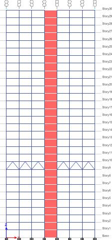
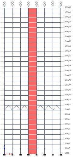
Locationofoutriggers:G+9,G+19,G+29
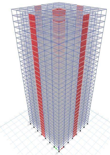
LocationofShearwall:Centreofperipherywall
Totalnoofmodels:20Models
International Research Journal of Engineering and Technology (IRJET) e-ISSN: 2395-0056
Volume: 13 Issue: 04 | Apr 2026 www.irjet.net p-ISSN: 2395-0072 © 2026, IRJET | Impact Factor value: 8.315 | ISO 9001:2008
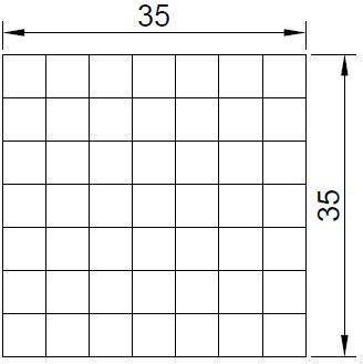
FIG.3.1 PLAN
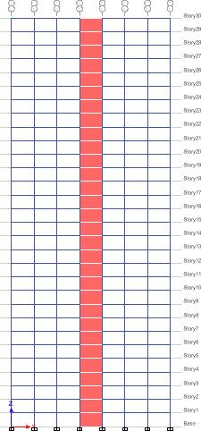
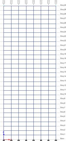
ELEVATION
International Research Journal of Engineering and Technology (IRJET) e-ISSN: 2395-0056
Volume: 13 Issue: 04 | Apr 2026 www.irjet.net p-ISSN: 2395-0072
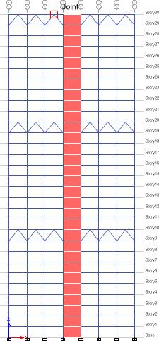
FIG.3.5.R.C.BUILDING SHEARWALL& OUTRIGGER AT 10 20 AND 30 STOREY
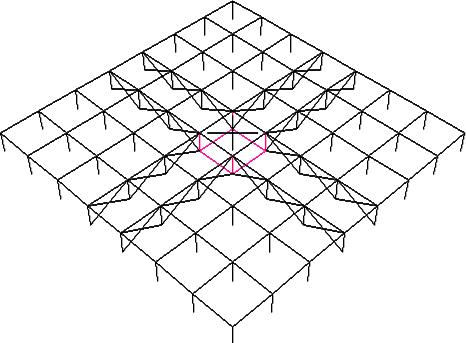
FIG.3.6. Perspective view of the model with central core and extended outrigger on all thefour sideswithout belt truss.
3.5 Loading Conditions
Thestructureissubjectedtothefollowingloads:
1. Dead Load (DL) Self-weightofstructuralcomponents
Floorfinishload
2. Live Load (LL)
AsperIS875(Part2)
3. Earthquake Load (EQ) AsperIS1893(Part1):2002
SeismicZonesconsidered:
o ZoneIII(Ahmedabad)
o ZoneV(Bhuj)
Soiltype:Mediumsoil
Responsereductionfactor(R):5
4. Wind Load
AsperIS875(Part3)
3.6 Analysis Procedure
G+30 Building
ZoneIII 3482 kN
ZoneV 7834 kN
International Research Journal of Engineering and Technology (IRJET) e-ISSN: 2395-0056
Volume: 13 Issue: 04 | Apr 2026 www.irjet.net p-ISSN: 2395-0072
4.0. Result and comparison
International Research Journal of Engineering and Technology (IRJET) e-ISSN: 2395-0056
Volume: 13 Issue: 04 | Apr 2026 www.irjet.net p-ISSN: 2395-0072
Displacement In X (Z-III )

Displacement ( mm )
4.1: StoryDisplacementinXDirectionForZ-III(A-B-C)
Displacement In X (Z-III )

Displacement ( mm )
outrigger at 10 storey
outrigger at 30storey outrigger at 20 storey outrigger at 10 ,20 and 30 storey
4.2: StoryDisplacementinXDirectionForZ-III(D-E-F-G)
Displacement In X (Z-III )
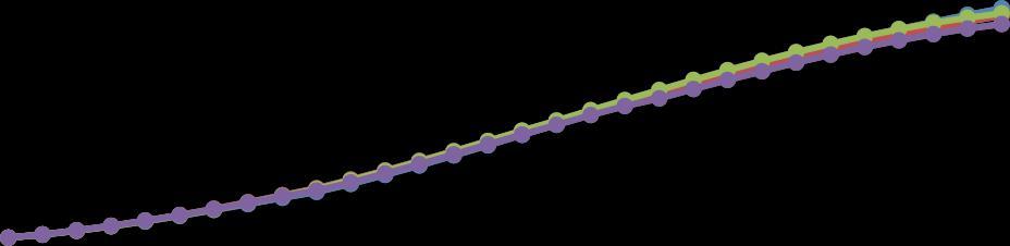
Displacement ( mm )
SW & outrigger at 10 storey
SW& outrigger at 30 storey
SW & outrigger at 20 storey
SW &outrigger at 10 ,20 and 30 storey
4.3: StoryDisplacementinXDirectionForZ-III(H-I-J-K)
International Research Journal of Engineering and Technology (IRJET) e-ISSN: 2395-0056
Volume: 13 Issue: 04 | Apr 2026 www.irjet.net p-ISSN: 2395-0072
Displacement In X (Z-III )
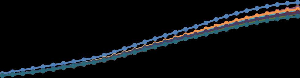
Displacement In X (Z- V )
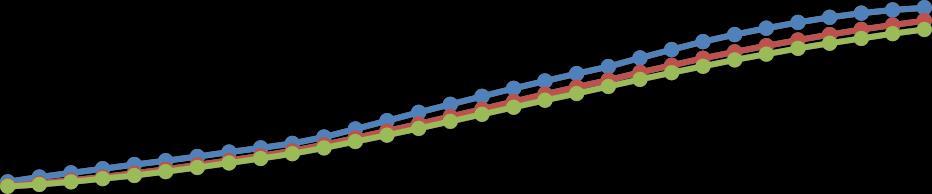
4.4: StoryDisplacementinXDirectionForZ-V(A-B-C)
Displacement

outrigger at
4.5: StoryDisplacementinXDirectionForZ-V(D-E-F-G)
International Research Journal of Engineering and Technology (IRJET) e-ISSN: 2395-0056
Volume: 13 Issue: 04 | Apr 2026 www.irjet.net p-ISSN: 2395-0072
Displacement In X (Z- V )
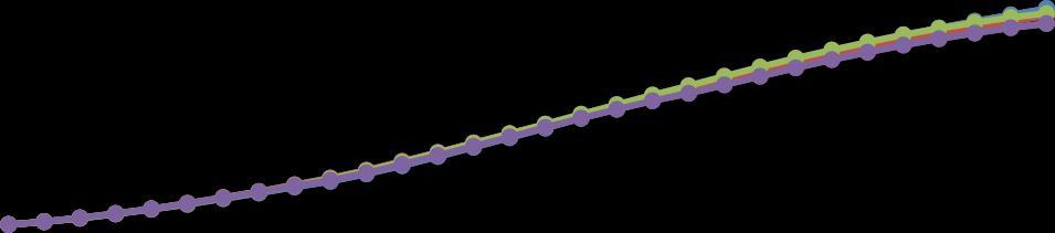
Fig 4.6: StoryDisplacementinXDirectionForZ-V(H-I-J-K)
Displacement In X (Z- V )
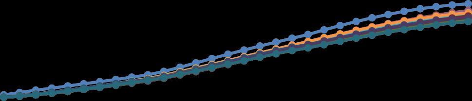
Fig 4.7: StoryDisplacementinXDirectionForZ-V(A-B-C-D-E-F-G-H-I-J-K)
Fig 4.8: BaseShearinXDirectionForZ-III(A-B-C-D-E-F-G-H-I-J-K)
International Research Journal of Engineering and Technology (IRJET) e-ISSN: 2395-0056
Volume: 13 Issue: 04 | Apr 2026 www.irjet.net p-ISSN: 2395-0072
Usingtheshearwallandoutriggerbothinbuildingreducesthestoreydisplacementcomparetoshearwalland outriggerindividual.
OptimumlocationofoutriggerisfoundatG+19ofbuildingtobetterreductionof storeydisplacementand storeyshear.
Storydisplacementweredecreasedby11.9%inshearwall,13.54%inoutrigger, 18.80%inshearwallwith outriggerinbuildingascomparedtoFramestructure.
Baseshearwereincreasedby18.51%inshearwall,16.38%inoutriggerand22.90%inshearwallwith outriggerascomparedtoframestructure.
[1]JamesHelal ,DarioTrabucco,DaliborSavovic”Embodiedcarbonpremiumforvanityheight:Acasefortheexclusionof decorativespiresinthedesignoftallbuildings”,Elsevier,2024.
[2]MariaGraziaMallardi,GiuseppeD’Arenzo,PierFrancescoGiordano,MariaPinaLimongelli“Evaluationofoptimallateral resistingsystemsfortallbuildingssubjecttohorizontalloads”, ScienceDirect,2025.
[3]GiuliaAngelucci,FabrizioMollaioli,omarAlshawa.”Evaluationofoptimallateralresistingsystemsfortallbuildingssubject tohorizontalload.”Sciencedirect,2020.
[4]ZixiaoWang,komalrajana,Dan-Adriancorfar,KonstantinosDanielTsavdaridis“Automatedminimum-weightsizingdesign frameworkfortallself-standingmodularbuildingssubjectedtomultipleperformanceconstraintsunderstaticanddynamic windloads” Elsevier,2023.
[5]YogeshR.Carpenter,VishalA.Arekar,VimleshV.Agrawal. “SeismicAnalysisofBundledTallBuildingConnectedwith OutriggerSystem”.IARJSET,2023.
[6]HussinAhmadHasrat,WahidullahQazi,NajeebullahMomand.”EvaluationofLateralLoadResistingSystemsinHigh-Rise Buildings”IJCSRR,2024.
[7]SurajSangtiani,SimonJ,SatyanarayanaJ,DheerajSangtiani”]PERFORMANCEOFTALLBUILDINGS UNDERLATERAL LOADSWITHDIFFERENTTYPEOFSTRUCTURALSYSTEMS”IJCIET,2017.
[8]VishveshJayswal,AakashSuthar“AReviewonBehaviorofConnectedTallBuildingswithLateralLoadResistingSystems andDampersUnderSeismicLoad”IRJET,2024.
International Research Journal of Engineering and Technology (IRJET) e-ISSN: 2395-0056
IS1893(Part1):2002IndianStandard,“CriteriaforearthquakeresistantdesignofstructureGeneralprovisionand buildings,“BureauofIndianStandard,NewDelhi.
IS456:2000,“Plainandreinforcedconcrete-codeofpractice”byBureauofIndianStandard,NewDelhi.
IS-456,“Codeofpracticeforplainreinforcedconcretecodeofpractice,”BureauofIndianStandards,NewDelhi,2000.
IS-875:1987, “Code for Wind load design of structures-general provisions for buildings”, Part iii Bureau of Indian Standards,NewDelhi.
Volume: 13 Issue: 04 | Apr 2026 www.irjet.net p-ISSN: 2395-0072 © 2026, IRJET | Impact Factor value: 8.315 | ISO 9001:2008 Certified