
International Research Journal of Engineering and Technology (IRJET) e-ISSN: 2395-0056
Volume: 13 Issue: 02 | Feb 2026 www.irjet.net p-ISSN: 2395-0072
International Research Journal of Engineering and Technology (IRJET) e-ISSN: 2395-0056
Volume: 13 Issue: 02 | Feb 2026 www.irjet.net p-ISSN: 2395-0072
Ismail 1 , Dr. N.Jayaramappa 2
1PG Student, Civil Engineering, University of Visvesvaraya College ofEngineering, Bangalore-560056, India
2 Professor, Civil Engineering, UniversityofVisvesvaraya College of Engineering, Bangalore-560056, India
Abstract: This project focuses on the structural analysis of a G+8 reinforced cement concrete commercial office building with the help of ANSYS Workbench. The main aim is to understand how the building behaves under different loads such as dead load, live load, and wind or seismic effects A 3D model of the structure is created, material properties are assigned, and suitable boundary conditions are applied before running the analysis. The study observes Total deformation, Stresses distribution and Natural frequency overall building structure. By using simulation, it becomes easier to identify critical areas and evaluate safety without physical testing. The results help in understanding the performance of the building and support better design decisions for safe and efficient construction. This work also highlights the importance of numerical simulation in modern structural engineering practice. Instead of depending only on manual calculations, ANSYS Workbench allows detailed visualization of how forces travel through beams, columns and slabs. The response of the structure is studied through stress patterns and displacement results, which helps in understanding whether the building satisfies basic safety and serviceability requirements, the simulation stresses are within the allowable permissible limit’s as per standard IS 456-2000 code for the concrete [M25] material.
Keywords: Commercial Office Building G+8, Static Structural Analysis, Equivalent von misses Stresses, Modal Analysis Natural Frequency,
This project report presents the planning, design, and construction of a G+8 commercial office building made with M25 grade concrete.The building is designedtomeet modern standards ofsafety, functionality, and aesthetics, while ensuring durability and cost- effectiveness. The structure consists of a ground floor and eight upper floors, which will be used for commercial and office purposes. Eachfloor is planned to provideflexible working spaces, conferencerooms, and service areastosupportthedailyoperationsofbusinesses.Themaingoalofthisprojectistocreateasafeandsustainablebuilding thatmeetsthegrowingdemandforofficespacesinurbanareas. Thedesignfocusesonproperspaceutilization,structural stability,andefficientuseofmaterials.Specialattentionhasbeengiventoprovidingadequatenaturallight,ventilation,and accessibility featuresto create a comfortableenvironmentforusers.Thebuildingisconstructedusingreinforcedcement concrete (RCC) with M25 grade concrete, which offers good strength and durability for multi-story structures. M25 concrete, with a characteristic compressive strength of25N/mm²,is suitableforheavyload-bearingcomponentssuchas columns, beams, and slabs. The reinforcement used in the structure helps resist tension and improves the overall performance of the building under various loads. Modern construction techniques and equipment have been used to maintain quality and ensure timely completion of the project. The design also follows relevant Indian Standards (IS codes) for structural design, earthquake resistance, and safety provisions. Environmental aspects, such as waste management,waterconservation,andenergyefficiency,havebeenconsideredtomakethebuildingeco-friendly.
Concrete [M25]: M25gradeconcreteiswidelyusedinRCCbuildingsbecauseitprovidesgoodstrength anddurabilityfor structuralmembers.Itisdesignedtoachieveacompressivestrengthof25MPaafter28daysofpropercuring.Thisgradeis suitable for beams, columns, slabs, and footings in multi-story structures. M25 concrete offers a good balance between strength and workability, making it easy to place and compact at theconstruction site. With propermixing and curing, it ensuressafety,stability,andlong-termperformanceofthebuilding.
Table 1: Materials Properties based of Concrete [M25]
Property’s Units Concrete [M25]
International Research Journal of Engineering and Technology (IRJET) e-ISSN:
Volume: 13 Issue: 02 | Feb 2026 www.irjet.net p-ISSN: 2395-0072
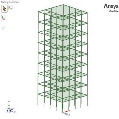
Fig 1: CADModel in Ansys space claim
Table 2: G+8 Commercial building Dimensions
Plandimension 18592x13716(mm)
TotalHeightofthebuilding 27000(mm)
HeightofEachStory 3000(mm)
SizeofTheBeam 450x450(mm)
SizeofTheColumn
SlabThickness
WindSpeed
(mm)
(mm)
The Fig:1TheG+8RCCbuildingmodelledinAnsysSpaceclaim.Theelevationhelpsinunderstandingthetotalheight,story arrangementandstructural configurationusedforthestudy.Itgivesaclearideaof howthebuildingispositionedbefore applyingloadssuchasdeadload,liveload,andwindorseismiceffectsduringtheanalysisstageofthemodelproperly.
International Research Journal of Engineering and Technology (IRJET) e-ISSN: 2395-0056
Volume: 13 Issue: 02 | Feb 2026 www.irjet.net p-ISSN: 2395-0072
AlltherequireddimensionsfortheRCCcommercialbuildingasshownin Table:2 includingcolumnsizes,beamsizes,slab thicknessandoverallbuildingheight,havebeenclearlydefinedbeforestartingtheanalysis.Thesedetailshelpincreating an accurate structural model. Proper dimensional data ensures correct load calculation, safe design, and realistic results duringanalysis.
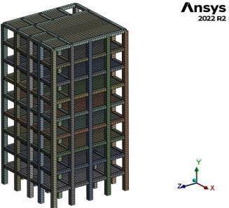
The Fig 2 showsameshedmodelinAnsysworkbenchsoftware.InAnsysworkbenchthemeshqualitywillbesmoothitcan meshcomplexobjectwithoutanyerror,alsousingwashers wherethereisaholepresenttogetbestelementswithoutany othermixingelements,the Table:4 showsbelowthemeshingdetailsinAnsysworkbenchwithnodeas20651andelement 18010.ThismeshedmodelisusedinAnsysworkbenchtoanalyzethenaturalfrequency,stresses,strain,deformationand
International Research Journal of Engineering and Technology (IRJET) e-ISSN: 2395-0056
Volume: 13 Issue: 02 | Feb 2026 www.irjet.net p-ISSN: 2395-0072
Table 4: Meshed details
3. Methodology
First,aliteraturesurveyontheRCCcommercialbuildingwasdonetounderstandthebasicconceptsandpreviousstudies. Then, materials wereselectedbasedontheirmechanical properties.Afterthat, wallloadandwindloadswerecalculated. Next, the building model was created in ANSYS Workbench 2022. The model was then meshed and imported into the softwareforanalysis.Suitableboundaryconditionswereappliedtorepresentrealsupportconditions.Structuralanalysis was carried out to find the equivalent von Mises stress, equivalent strain, and total deformation of the structure. Modal analysiswasalsoperformedtodeterminethenaturalfrequencyofthebuilding.Finally,theconclusionsweremadebased ontheresultsobtainedfromtheanalysis.
4. Results & Discussion
a. Calculation Of Wind Load
1.1 WIND LOAD CALCULATION AS PER IS 875 PART-3
WindPressure:
P=0.6xVz2 (01)
Designwindspeed: Vz=VbxK1xK2xK3xK4
HereK2isTerrainheight&StructuralsizeFactorTable2Page24TerrainCategory(3)Structuralsize (B)NormalsizeBuilding
Here(Vb)isBasicwindspeed(m/s)ForBangaloreis33m/sPage23Here(K1)isRiskCoefficientFactor. Here(K3)isTopographyFactor.
Here(K4)isImportantFactorForthecyclonicregionVz=33x1x0.88x1x1=28.02m/s
P=0.6x(28.02)2 = 439 N/m2 OR 0.000439 MPa
ButIwantin(Newton)toapplyBecauseofwehavebeamsnotasolidbodysopressureCan’tbeappliedonbeamssowe havetoconvertpressureintowindforcesothewindforcecanbeappliedonbeams&column.
A=HXW
A=3000X18592A=55.7M2
Force=P*A
F = 439 x 55.7 = 2447202 N G L Force (03)
1st FLOOR CALCULATION (WIND FORCE) (04)
Vz=33x1x0.94x1x1=31.02m/s
P=0.6X(31.02)2=484.6N/M2or0.000484MPaF=484x55.7 = 27002 N
International Research Journal of Engineering and Technology (IRJET) e-ISSN: 2395-0056
Volume: 13 Issue: 02 | Feb 2026 www.irjet.net p-ISSN: 2395-0072 © 2026, IRJET | Impact Factor value: 8.315 | ISO 9001:2008 Certified Journal | Page555
2nd FLOOR CALCULATION
Vz=33x1x0.97x1x1=32.02m/s
P=0.6x(32.02)2 =518N/M2OR0.000518MPa
F=518x55.7 = 28852 N (05)
3nd FLOOR CALCULATION
Vz=33x1x0.94x1x1=31.02m/s
P=0.6x(31.02)2 =0.000517MPa
F=517x55.7 = 29000 N (06)
4th FLOOR CALCULATION
Vz=33x1x1.02x1x1=33.66m/sP=0.6x(33.66)2 =0.000580MPa F=580x55.7 = 32193 N (07)
5th FLOOR CALCULATION
Vz=33x1x1.03x1x1=34m/sP=0.6x(34)2 =0.000605MPa
F=605x55.7 = 33639 N (08)
6th FLOOR CALCULATION
Vz=33x1x1.06x1x1=34.98m/sP=0.6x(34.98)2 =0.000626MPa F=626x55.7 = 34925 N (09)
7th FLOOR CALCULATION
Vz=33x1x1.08x1x1=36m/sP=0.6x(36)2 =0.000642MPa F=642x55.7 = 35818 N (10)
8th FLOOR CALCULATION
Vz=33x1.09x1x1=36.5m/sP=0.6x(36.5)2=0.000655MPa F=655x55.7= 36431 N (11)
1.2 WALL LOAD’S CALCULATION: Wall Thickness x Height x Density of Brick Masonry
0.230x3x20
13.8KN/m (12) Plasterload(bothsides)20mmThickness.
0.02+0.02=0.04m
0.04x3x20=2.4KN/m
TotalwallloadsonBeam’s:
13.8+2.4 = 16.2 KN/m OR N/mm (13)
International Research Journal of Engineering and Technology (IRJET) e-ISSN: 2395-0056
Volume: 13 Issue: 02 | Feb 2026 www.irjet.net p-ISSN: 2395-0072 © 2026, IRJET | Impact Factor value: 8.315 | ISO 9001:2008 Certified Journal | Page556
1.3 Force Reaction:
• Slab dead load =ThicknessxDensityofRCC
=0.15x25
=3.75KN/m2
• Floor Finish =1KN/m2
TotalDeadloadofSlab=3.75+1=4.75KN/M2
• Beam Dead Load =AreaxDensity
=0.45x0.45x25
=5.06KN/m
• Column Dead Load =AreaxHeightxDensity
=0.60x0.60x27x25 =243KN/m
• Wall Dead Load =ThicknessxHeightxDensity
=0.230x27x20 =124.30KN/m
• TotalLive Load =includingallLiveload =41KN/m2
FORCE REACTION = 40800000 N
REFFERANCE: IS 875 PART -1(Clause 3.1)
ItissayingthatDeadloadshallbecalculatedbasedonunitweightofmaterial&assumeddimension.
In my case 36523305.42N
Only9%Difference(5–10%isVariationisAllowed)
1.4 EQUIVALENT VON- MISES STRESS:
(ASPERIS456-2000Clause36.4.2DesignCompressiveStressinConcrete)
Fcd=Fck /γm
=25/1.5
=6.50 MPa <16.67 MPa (Itiswithinit’sPermissibleLimit’s)
Von–MisesstressismainlyusedforDuctilemateriallikesteelConcreteisbrittlematerialbutAnsysshow’s Von-misesstresstounderstandoverallstressBehavior’s.
International Research Journal of Engineering and Technology (IRJET) e-ISSN: 2395-0056
Volume: 13 Issue: 02 | Feb 2026 www.irjet.net p-ISSN: 2395-0072
1.5 MAXIMUM PRINCIPAL STRESS:
ASPERIS456-2000CLAUSE6.2.2TheTensileStrengthofConcreteis3.5MPa
0.7x√fck=0.7x√25=3.5MPa
3.5 < 7.23 MPa
• ItIsPracticallyAcceptable
• RCCmembertransfertensiontosteelreinforcement
• PrincipalStressPointAnsysShowsStressinOverallMaterialModel.
1.6 MINIMUM PRINCIPAL STRESS:
ASPERISCODE456-2000(Clause38.1)
=0.45xFck
=0.45x25
=-7.09 MPa < - 11.25 MPa (Hence the structure is safe under applied loading condition).
1.7 MAXIMUM SHEAR STRESS:
ASPERIS456-2000(Clause 40.2.3)&Table20
M25 3.1MPa
In my case3.6 MPa> 3.1 MPa(only 0.5 % Difference it is acceptable)
• Solution:Gradeofconcreteweneedtoincrease
• ProvidingAdditionalShearReinforcementIncreaseSectionSize
1.8 EQUIVALENT ELASTIC STRAIN:
ASPERISCODE456-2000(Clause38.1(b))
ItIsCalculatedBasedonHooke’sLaw
S t r a i n = σ / E
It isup to 0.0003 to0.0035Before Cracking Starts In my case 0.00026 < 0.0035 (it is with in its Limit).
• TheStructureisworkinginsafeElasticRange
• NoExcessiveDeformation
• ItIswithInItsPermissibleLimit’s.
2026, IRJET | Impact Factor value: 8.315 | ISO 9001:2008
International Research Journal of Engineering and Technology (IRJET) e-ISSN: 2395-0056
Volume: 13 Issue: 02 | Feb 2026 www.irjet.net p-ISSN: 2395-0072
b. ANSYS RESULT’S:
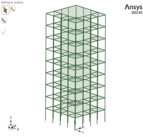
This fig:3 presents the side view of the G+8 RCC building modelled in ANSYS Workbench. The elevation helps in understandingthetotalheight,storeyarrangement,andstructuralconfigurationusedforthestudy.Itgivesaclearideaof how the building is positioned before applying loads such asdeadload,live load, andwindor seismic effects during the analysisstageofthemodelproperly.
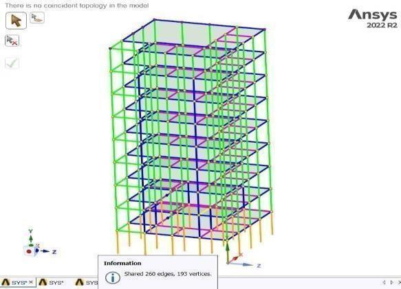
The Fig:4 showsthatfirst,inANSYSSpaceClaim,Ihavemodelledthestructure.Oncethat’sdone,I haveselected the entire building. After that, I have selected the each joint individually. Then, whenall joints areselected,theredcolorshouldbe shown.Oncethey’rehighlightedinred,thereisagreentickoptionatleftsideaftertickingthatthecheckbox for theshear check.Afterdoingthat,notificationwillcomesayingthat“Thereisnoshear.Meansthestructureisinbondedconnection betweencolumn,beam&slab. Beforeapplyinganyexternalloads,theRCCG+8buildingmodelwascheckedinANSYSWorkbench.Atthisstage,noshear effectwasobservedinthestructure,confirmingthatthemodelisstableandfreefrominitialshearstressesbeforeloading.
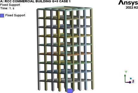
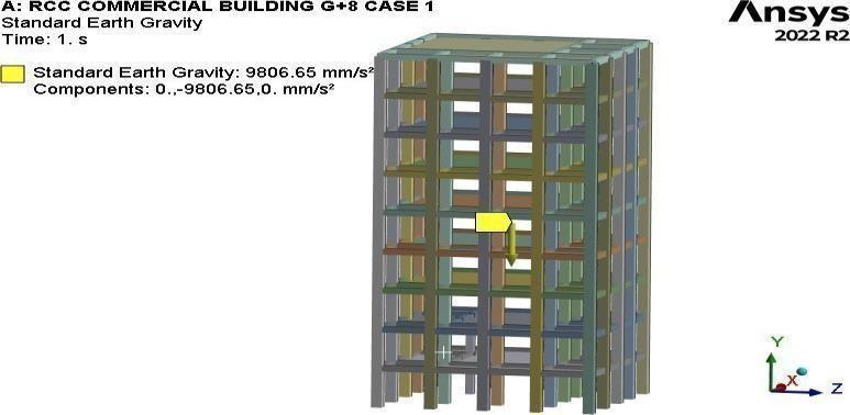
The Fig:5, shows the Fixed Support are provided at the base of the G+8 building to represent the actual foundation condition.Thesesupportsrestrictmovementandrotationofthestructureatgroundlevel,ensuringstabilityandrealistic loadtransfertothefoundation. Fig:6 showsthegravityloadactingonthestructureindownwarddirection&itistakenas 9806.65mm/s2,whichrepresentthenaturalgravitationalaccelerationoftheearth.
International Research Journal of Engineering and Technology (IRJET) e-ISSN: 2395-0056
Volume: 13 Issue: 02 | Feb 2026 www.irjet.net p-ISSN: 2395-0072
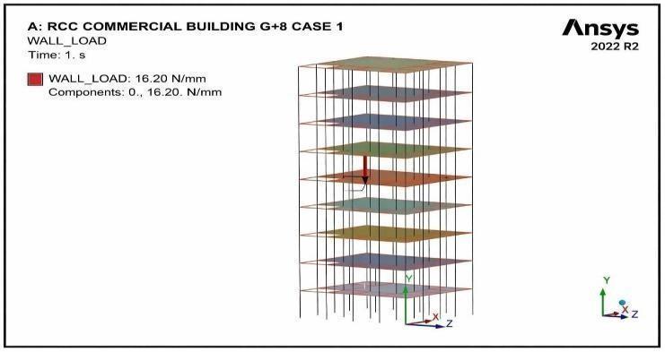
WallLoad Actingonstructure.
Theself-weightofbrickwallsandfinishinglayerscreateswallloadinthestructure.Thisloadactscontinuously alongthe supportingbeamsandistransferredtocolumnsandfoundations.ForthisRCCG+8commercialbuildingmodel,wallloadis consideredasuniformlydistributedloadtosimulaterealsiteconditions.Anditsvalveistakenas16.2N/mm.
International Research Journal of Engineering and Technology (IRJET) e-ISSN: 2395-0056
Volume: 13 Issue: 02 | Feb 2026 www.irjet.net p-ISSN: 2395-0072
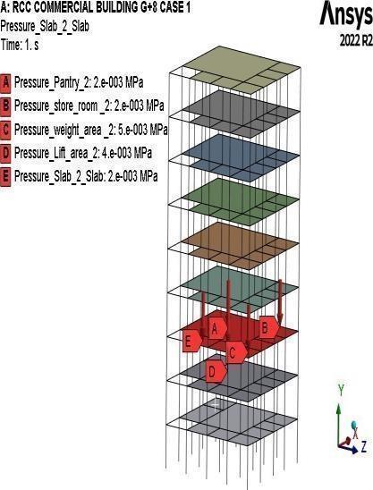
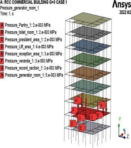
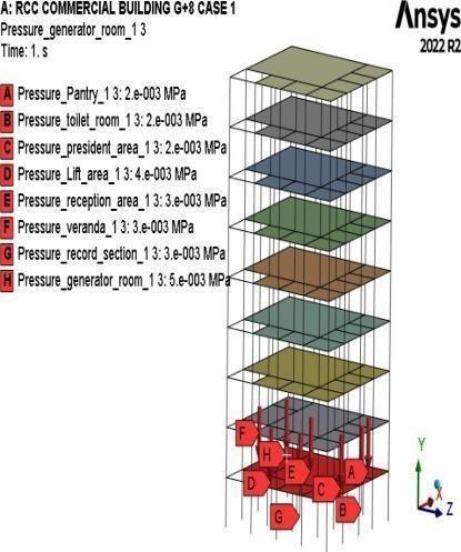
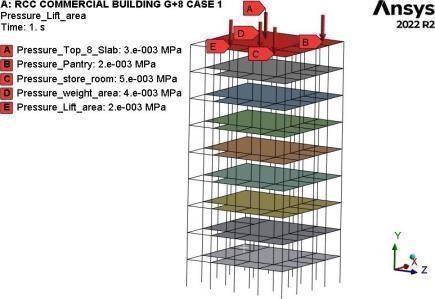
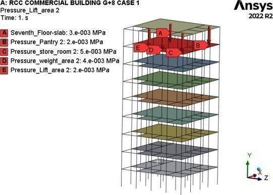
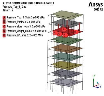
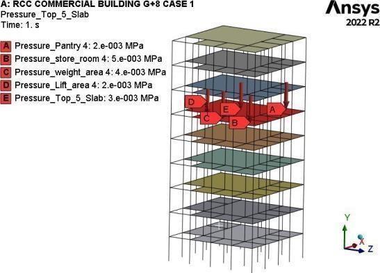
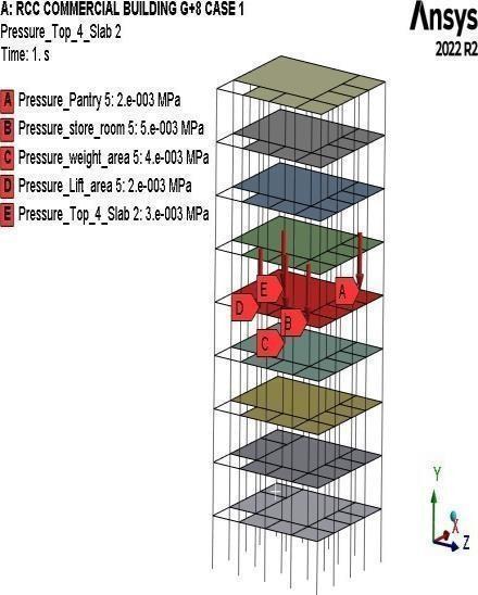
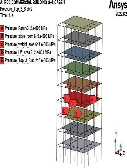
Fig: 8 Live load’s acting on each & every floor.
theliveloadisappliedanddistributedoneveryflooroftheG+8commercialbuilding.Ithelpsinunderstandinghowload transfertakesplacethroughdifferentstructuralmembers.
CASE1:RESULT’SWHENSTRUCTURE CARRYS DEAD &LIVELOAD’S:
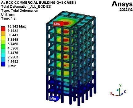
Fig:9 Total Deformation.
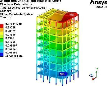
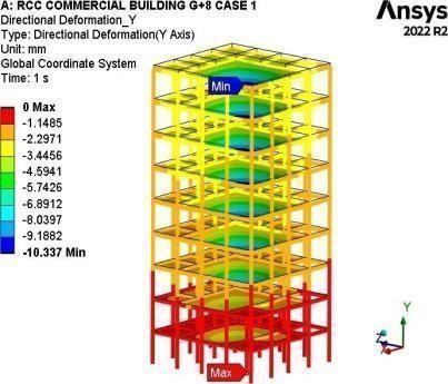
Fig: 10 Deformation (X-Axis) Fig:11 Deformation in (Y)
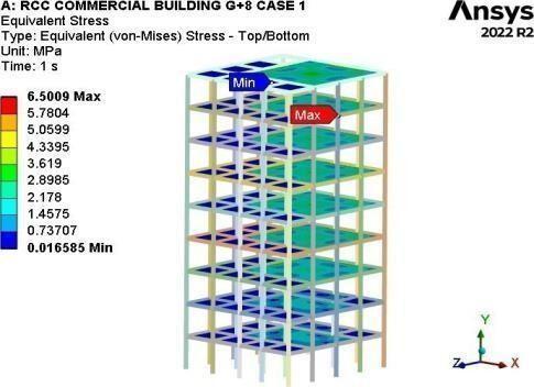
Fig: 12 Equivalent (Von– Mises) Stress.
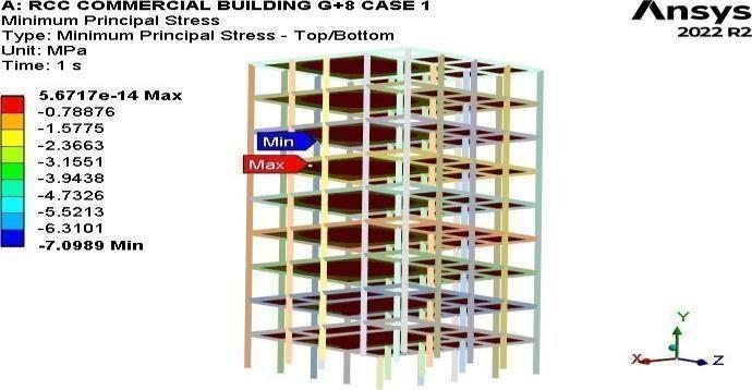
Fig: 13 Minimum Principal Stress.
The Fig:9 Thedeformationisminimumatthebasearound 0 mm becauseoffixedsupportandmaximum atthe topfloor duetoloadeffects&itisaround 10.34 mm Fig:10 ThisresultshowsDirectionalDeformationintheXdirection.Thebase
© 2026, IRJET | Impact Factor value: 8.315 | ISO 9001:2008 Certified Journal | Page560
International Research Journal of Engineering and Technology (IRJET) e-ISSN: 2395-0056
Volume: 13 Issue: 02 | Feb 2026 www.irjet.net p-ISSN: 2395-0072
portionhasminimumdeformationbecauseitisfixed,anditisaround - 0.040161 mm deformationincreasestowardsthe top floors. Is around 0.37881 mm Fig: 11 Theanalysis resultsindicatethat the displacement of the structure in the Ydirectionis zero atcertainlocations Fig: 12. Themaximum stress is mainlyobservednear beam-columnjoints andload transferareasisaround 6.5009 MPa &Minimumstress ismainlyobservedslab-beamisaround 0.016585 MPa. Fig: 13 higher compression is obtained near beam and column joint areas because these regions carry more load. Is around7.0989 MPa
CASE 2: RESULT’S WHEN STRUCTURE CARRYS DEAD, LIVE LOADS & WIND LOAD’S:
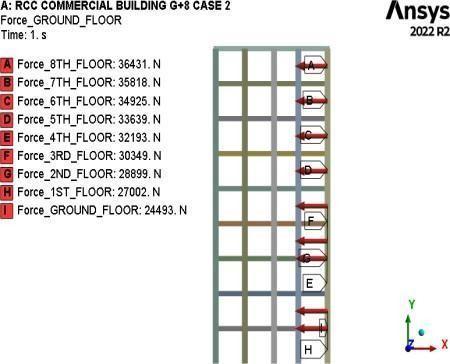
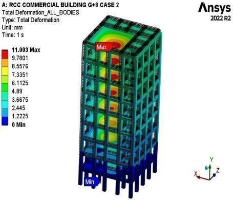
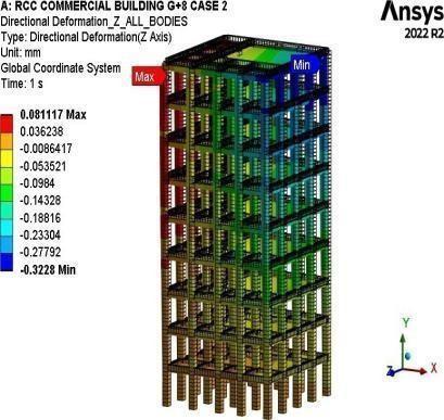
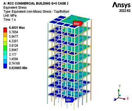
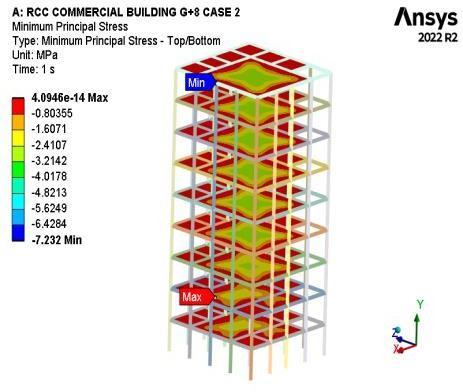
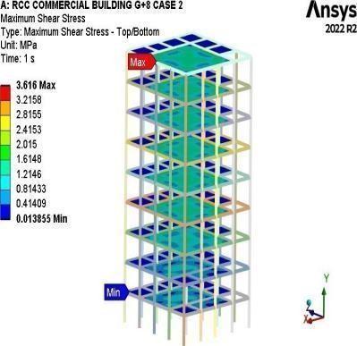
Fig:14 WindloadisactingonthebuildingintheX-direction,solateralforcesaredevelopedateveryfloorlevel.Fromthe result,itcanbeunderstoodthattheupperfloorsaremoreaffectedbecausetheyaredirectlyexposedtowindpressure.Due tothisload,thestructureshowsasmallsidemovement,andtheframeresiststhisactiontomaintainoverallstabilityand safetyofthebuilding. Fig: 15 Thedeformationisminimumatthebasearound 0 mm becauseoffixedsupportandmaximum at the top floor due to load effects & it is around 11.003 mm. Fig: 16 The result shows that the maximum Z-direction deformation is about 0.081117 mm, and the minimum value is 0.3228 mm. Fig: 17 The maximum stress is mainly observed near beam-column joints and load transfer areas is around 6.4831 MPa & Minimum stress is mainly observed slab-beam is around 0.024005 MPa Fig: 18 higher compression is obtained near beam and column joint areas because theseregionscarrymoreload.Isaround - 7.2320 MPa Fig: 19 TheMaximumshearstressismainlyobservednearbeam andcolumnconnectionareasisaround 3.616 MPa andlowerfloorsbecausethesepartscarrymoreload.Theupperfloors showlessshearstressisaround 0.013855 MPa
International Research Journal of Engineering and Technology (IRJET) e-ISSN: 2395-0056
Volume: 13 Issue: 02 | Feb 2026 www.irjet.net p-ISSN: 2395-0072
Table:5 Static structural Analysis Results ofG+8 Commercial Building
RCC
G+8 RCC
Table:6 Allowable Permissible Limit’s AS PER IS 456-2000 For M25 Grade Concrete.
C. MODEL ANALYSIS RESULT:
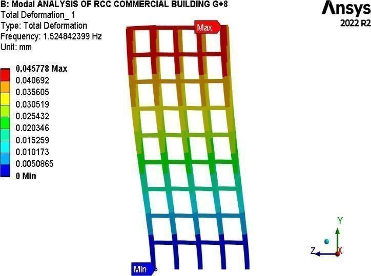
Fig:20 .1st Mode Frequency.
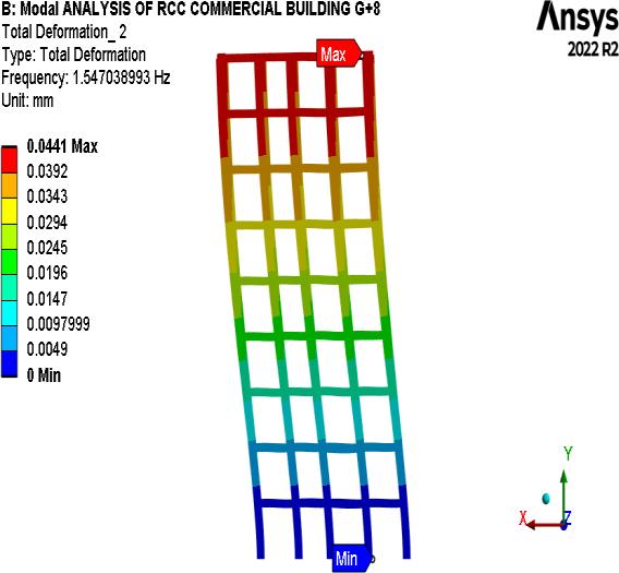
Fig:21. 2nd Mode Frequency.
International Research Journal of Engineering and Technology (IRJET) e-ISSN: 2395-0056
Volume: 13 Issue: 02 | Feb 2026 www.irjet.net p-ISSN: 2395-0072
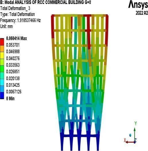
22. 3rd Mode Frequency
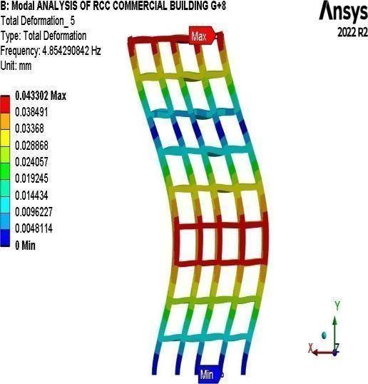
5thMode Frequency
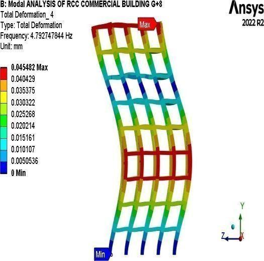
23 .4thMode Frequency
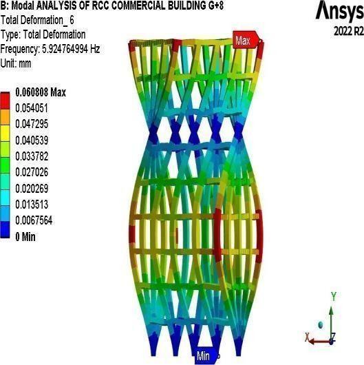
Fig:25. 6th Mode Frequency.
The Fig:20 to 25 SixmodesofthenaturalfrequencyoftheG+8RCCCommercialBuildingmaterial,thefrequencyincreases lowtoohighindifferentmodesandlocation.Itcanbeobservedthatthefrequencyisincreasingupto 5.924764 Hz from initialmodetofinalmodeasperresults.
International Research Journal of Engineering and Technology (IRJET) e-ISSN: 2395-0056
Volume: 13 Issue: 02 | Feb 2026 www.irjet.net p-ISSN: 2395-0072







Chart: 1 Shows the Frequency vs. Modes ofthe G+8 RCC Commercial Building.
Table7: Natural Frequency of the G+8 Commercial Building
5 CONCLUSIONS:
5.1 Static Structural Analysis:
Fromtheanalysisresults,itisobservedthatallthestressesdevelopedinthestructurearewithinthepermissiblelimitsas specified inIS 456:2000.This indicates that theRCC commercial building is structurallysafeundertheapplied loads and boundaryconditions.Thedeformationandstrainvaluesarealsowithinacceptablelimits,showingthatthedesignisstable, reliable,andsuitableforpracticalconstruction.
5.2 Modal Analysis:
IneverymodethemaximumdeformationsareobservedattheTopfloorsofthebuilding. Inmodalanalysisareperformedfor6modes,instartingthreemodesareveryflexible&remaining4,5&6modesarestiff. Weseethatnaturalfrequencyincreasingconsistentlyforallsixmodes.
International Research Journal of Engineering and Technology (IRJET) e-ISSN: 2395-0056
Volume: 13 Issue: 02 | Feb 2026 www.irjet.net p-ISSN: 2395-0072
[1]. Baldev D. Prajapati & D. R. Panchal ‟Study of Seismic and wind effection multi storey R.C.C., steel and compositebuilding‟InternationalJournalofAdvancesinEngineering&Technology,Sept.2013.
[2]. Prof. S. S. Charantimath, Prof. Swapnil B. Cholekar, Manjunath M. Birje‟‟ Comparative Study on Structural Parameter of R.C.C and Composite Building‟‟ Civil and Environmental Research ISSN 2224-5790 (Paper) ISSN 2225-0514(Online)Vol.6,No.6,2014.
[3]. Harish Soundalgekar and Kshitij S Patil, Comparative Study of Reinforced Cement Concrete and Steel Structures,InternationalAdvancedResearchJournalinScience,EngineeringandTechnology,Vol.10,Issue5,May 2023.PP476-478.
[4]. Md.Yaser and Ajith Kumar Dey, Comparative Cost Analysis and Dynamic Analysis Of RCC, Steel and SteelConcrete Composite Frame ofLow, Medium & High-RiseBuildings, Journal ofEngineering Sciences, Vol13,Issue 10,2022,PP301-309.
[5].JadhavGorakhnathS,et.al,ComparativeAnalysisofRCCAndSteel-ConcreteCompositeMultistoriedBuilding, JournalofInformation,KnowledgeandResearchinCivilEngineering,Volume4,Issue2,2022,PP398-404.
[6]IS:875(Part1):1987,˝CriteriaforDeadloadsDesignofStructures˝.
[7]IS:875(Part2):1987,˝CriteriaforLiveLoadsDesignofStructures˝.
[8]IS456-2000”PlainandReinforcedconcrete.Codeofpractice”
[9]IS:875(Part3):1987,˝CriteriaforWindloadDesignofStructures˝
[10] Sayyed A. Ahad, Hashmi S Afzal, Shivaj and Shaikh Ammar. “Analysis and Design of Multistory Apartment BuildingUsingETABS”,InternationalJournalofEngineeringandComputerScienceISSN:2319-7242.