
International Research Journal of Engineering and Technology (IRJET) e-ISSN: 2395-0056
Volume: 13 Issue: 05 | May 2026 www.irjet.net p-ISSN: 2395-0072
International Research Journal of Engineering and Technology (IRJET) e-ISSN: 2395-0056
Volume: 13 Issue: 05 | May 2026 www.irjet.net p-ISSN: 2395-0072
J. Lakshmi Durga1 , G. Mounika Lakshmi2 , M. Sindhuja3 , I. Sri Durga4 , T. Bhanu Prakash Kumar5 , Punnam Nagaraju6
12345 B. Tech Students, 6Assistant Professor, Department of Electronics and Communication Engineering, Sri Vasavi Engineering College, Tadepalligudem, Andhra Pradesh, India ***
ABSTRACT - This work presents a compact bandpassfilter (BPF) based on substrate integrated waveguide(SIW)andthe trident-shaped compact spoof surface plasmon polariton (SSPP) structure. In the proposed design, the lower cutoff frequency is primarily determined by the SIW dimensions, while the upper cutoff frequency is determined by integrating trident-shaped SSPP grooves on the top metal plane.SIWsand SSPPs exhibit low and high cutoff responses, respectively, which can be combined for filtering functionalities. The passbands can be flexibly selected by varying the geometric parameters of the SIW and SSPP to adjust thelowerandupper frequencies independently. The filter operates from 3.81 to 5.31 GHz, with a center frequency of 4.56 GHz and an FBW of 32.89%. It achieves an insertion loss of 0.56 dB at the center frequency, a return loss is greater than 12 dB across the passband, and a stopband rejection from 5.43 GHz to 10.06 GHz at 25 dB. It is highly suitable for C-band wireless applications
Key Words: Substrate Integrated Waveguide (SIW), Spoof Surface Plasmon Polariton (SSPP), trident-shaped groove, Bandpass filter (BPF), and compact design.
Microwave band-pass filters (BPFs) play a crucial role in modernwirelesscommunicationsystems,wheretheneed for high-performance microwave and millimeter-wave componentsiscontinuouslyincreasing.SubstrateIntegrated Waveguide(SIW)isanewtypeofplanartransmissionline that combines the positive attributes offered by metallic rectangular waveguides and traditional printed circuit boards,includinglowattenuationloss,minimalEMradiation losses, and decreased area. Due to these fundamental features, SIW filters become more attractive choices for variousmillimeterandmicrowavefrequencybandcircuits [1]. These filters are responsible for selecting desired frequencybandsandsuppressingunwantedsignalsduring transmission and reception. Among various technologies, Substrate Integrated Waveguide (SIW) has become a preferred choice for designing microwave components because it overcomes many limitations associated with conventionalwaveguides.SIW-basedfiltersofferadvantages such as low insertion loss, excellent electromagnetic shielding, and easy integration with planar circuits [2]. However, a major drawback of conventional SIW filters is theirrelativelylargephysicalsize,whichlimitstheirusein
compactandhighlyintegratedsystems[3].Toaddressthis issue, researchers have introduced band-pass filters that combineSIWwithspoofsurfaceplasmonpolaritons(SSPPs), including designs with trident-shaped complementary grooves [4]. SSPPs are artificially engineered electromagneticsurfacewavesthatpropagatealongmetaldielectric interfaces at microwave frequencies. By incorporating periodic sub-wavelength structures on metallic surfaces inspired by the principle of surface plasmon polaritons (SPPs), SSPPs enable strong field confinementandimprovedcontroloverwavepropagation [5].Duetotheseproperties,hybridSIW-SSPPfilterdesigns have gained attention, as they provide wideband performance and allow independent tuning of lower and upper stopband frequencies. In addition, compact narrowband BPFs designed using both SIW and SSPP techniquesaresuitableforhigh-frequencyapplicationssuch astheKa-band,whereimpedancematchingisoftenachieved using tapered transitions between microstrip lines and waveguidestructures.Thiscombinationprovidesseparate tuningofthelowerandupperstopbandfrequencies[6].A compact narrow-band BPF designed for Ka-band applications uses both SSPPs and SIW structures, with a sharpfunnel-shapedtaperconnectingthemicrostriplinesto ensureproperimpedancematching[7].Compactmicrowave filters with high selectivity can be designed by combining SubstrateIntegratedWaveguide(SIW)structureswithspoof surface plasmon polaritons (SSPPs). This integration improves control over wave propagation by modifying characteristicswhilealsoenhancingfieldconfinement[8]. As a result, the overall circuit size is reduced without degradingperformance[9].InSIW–SSPPband-passfilters, efficient transmission within the desired frequency range andstrongrejectionoutsidethebandareachievedthrough proper transition design between microstrip and SIW sections [10]. The use of periodic subwavelength corrugations enables SSPP modes, which shorten the effective guided wavelength and contribute directly to miniaturization[11].
In this paper, an SIW–SSPP-based band-pass filter incorporating a trident-shaped groove is developed. The proposed groove structure allows precise control of the uppercut-offfrequencywithoutincreasingtheSSPPsheight (h1).Theoperatingcharacteristicsaremainlygovernedby thegroovewidth(L5)andslotdepth(S_S),whichinfluence the behavior of the SSPP mode. A parametric study is
International Research Journal of Engineering and Technology (IRJET) e-ISSN: 2395-0056
Volume: 13 Issue: 05 | May 2026 www.irjet.net p-ISSN: 2395-0072
performed to optimize these parameters. The final design achievescompactsize,lowinsertionloss,improvedreturn loss, and strong suppression in the stopband, making it suitableforapplicationsintheC-bandfrequencyranges.
2.1 Design of classical SIW filter
The stated work starts with designing the classical SIW at requiredstructuraldimensionsasplottedinFig.1.
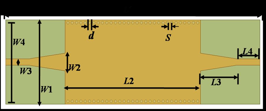

Fig. 1. ThelayoutoftheSIWfilter(a)toplayer(b)bottom layer
ThestandardSIWstructure'selectricalperformanceis similar to that of a classical waveguide. Equations (1), (2), and (3) in [2]–[3] are used to calculate the geometrical variablesandcutofffrequencyoftheSIWstructure.
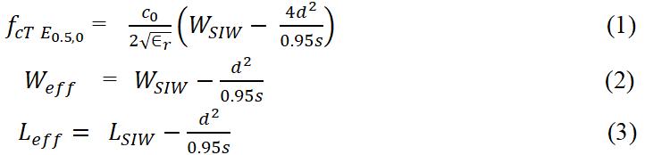
Fromabove,(1),(2),and(3)c0 arethelightvelocityinfree space WSIW and LSIW representtheSIWwidthandlength Weff and Leff definethe SIW effective widthand length. dis the copper via diameter, and S is the periodic space between vias. The standard SIW filter is defined in Fig. 1, and the employed precise measurements of the filter are tabulatedinTable1.
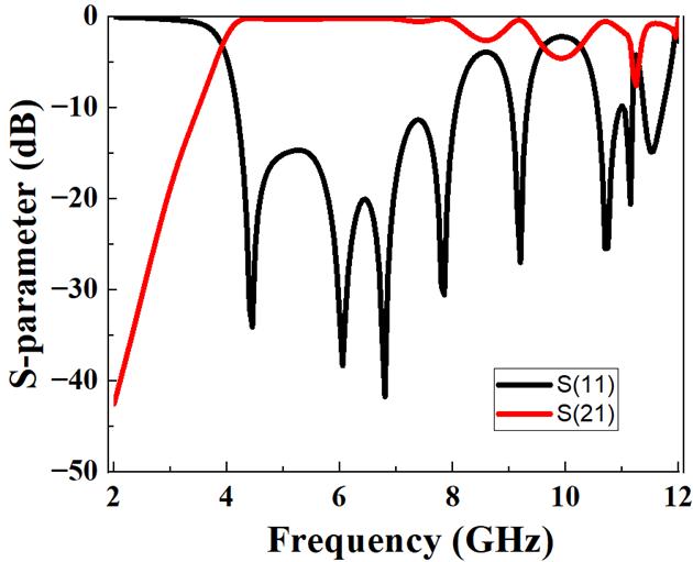
Fig. 2. Simulated output of SIW filter
ThesimulatedS-parametersoutputofthefilterisdefined in Fig.2; it indicates the passband starting frequency value of 3.81 GHz, having good return and insertion losses over the entire operating frequencyofthepassband.
Table 1. Dimensions of SIW filter
W1)
transition
(W2)
Feedwidth(W3) 2.3
(W4)
vias
transition length(L3) 13
2.2 Design approach of proposed SIW-SSPP-based bandpass filter
InordertoachievethebandpassexperienceattheC-band frequencyrange,themicrowavebandpassfilterisdesigned using both SIW and SSPPs, as shown in Fig. 3. This is achievedbyintegratingtrident-shapedgroovegrooves.Due to the high and low pass characteristics of both SIW and SSPPs, when a periodic arrangement of SSPP grooves is insertedintoastandardSIWfilter,thebandpassresponseis realizedasaresultofabandpassfilter.
Volume: 13 Issue: 05 | May 2026 www.irjet.net p-ISSN: 2395-0072
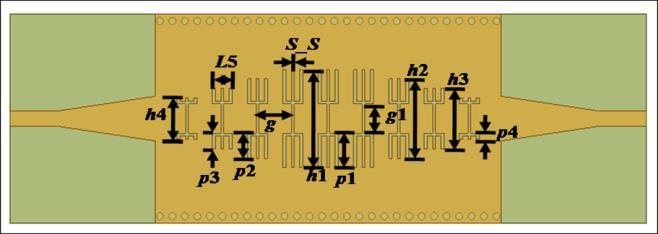
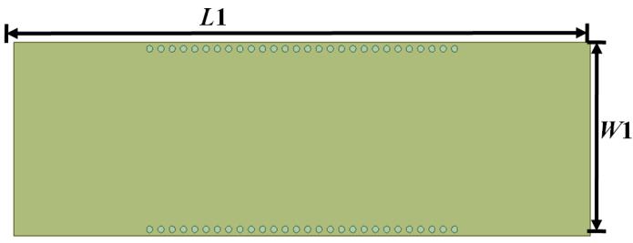
3. ConfigurationofproposedSIW-SSPPbandpass filter(a)Topview(b)Bottomview
AccordingtoFig.3,theoptimizeddimensionsfortheSSPP are considered as h1=14mm, h2=11.7mm, h3=9.4mm, h4=7mm, L5=2.8mm, g=5.1mm, p1=4mm, p2=2.85mm, p3=1mm,p4=2.85mm,S_S=0.3mm,andg1=3mm.
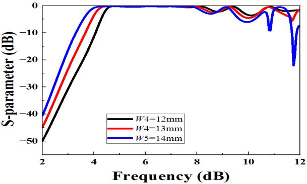
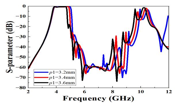
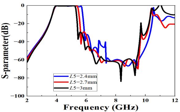
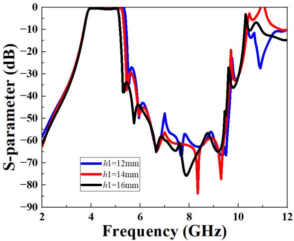
To achieve the desired passband frequency response, the proposedfilter'sphysicaldimensionsarechanged.First,itis foundthatchangingtheSIWeffectivewidth(W4)canchange thelowerpassbandfrequencyrange,asshowninFig.4(a), withvariousSIWeffectivewidth(W4)values.Itisevident thatthecut-offfrequencyfallsastheeffectivewidthofSIW risesandviceversa.Byaddingthehigh-passandlow-pass featuresofSIWandSSPPs,acompactwidebandbandpass filterisrealized.Thepassbandexhibitsthepassbandrange from 3.81 to 5.31 GHz. Further, the parametric study is performed to understand the impact of the structure’s physicaldimensionsonthefilterresponse.Now,parametric studies are conducted to evaluate the impact of tridentshapedgroovedimensionsonthefrequencyresponseofthe filter.First,itisnotedthatthelowercut-offfrequencyvalue ofthepassbandisindependentlycontrolledbythewidthof the SIW (W4). The upper cut-off frequency value of the passbandiscontrolledbytheheightoftheSSPPgroove(h1), asillustratedinfig.3(a).Forinstance,raisingtheW4from 12mmto14mm,thefrequencyshiftsfrom3.73GHzto9.88 GHz,asillustratedinfig.4(a).Similarly,raisingtheh1value from12mmto16mmmovesthefrequencyfrom3.83GHz to 5.39 GHz, as illustrated in fig. 4(b). For example, increasingtheL5valuefrom2.4mmto3mm,thefrequency valuemovesdownfrom3.84to5.71GHzasdepictedinfig. 4(c). If the p1 value is rising from 3.2 mm to 3.6 mm, the frequency value moves down from 3.77 to 5.04 GHz, as depictedinFig.4(d).
(d)
Fig. 4. .SimulatedoutputsofproposedSSPPsusingvarious values(a)Horizontalwidth(W4),(b)Heightofgrooves(h1), (c) Horizontal groove length (L5), (d) Vertical length of groove(p1)
International Research Journal of Engineering and Technology (IRJET) e-ISSN: 2395-0056
Volume: 13 Issue: 05 | May 2026 www.irjet.net p-ISSN: 2395-0072
Fig.4tellsthattheeffectofphysicalvariablevaluesofSSPPs’ trident-shapedgroovesinsertedontheupperplaneofthe device onthetransmission characteristicsofthestandard microwavebandpassfilterandtheirsimulatedresults.Asa result, it is evident that the passband upper edge can be readilymovedbysimplychangingtheSSPPstrident-shaped groovevariables,primarilyverticalgroovelength(p1),the horizontal groove length (L5), and groove length (h1), as showninFig.4.
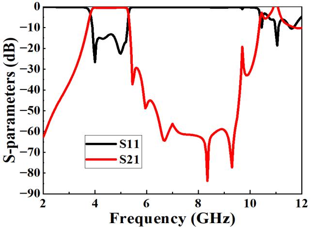
The Rogers RT/Duroid 5880 substrate, which has a thicknessof0.508mmandarelativepermittivityof2.2,is usedtodevelopandsimulateamicrowavebandpassfilter for C-band services. Fig. 5 defines the proposed bandpass filtersimulatedoutput.Byalteringthephysicalparameters of the SIW and SSPP structures, the passband's frequency range can be changed in relation to the bandwidth requirement. The bandpass filter is more compact in size, and the structure’s final footprint is 1.05 λg ×188 λg not includingthefeedline,whereλgistheguidedwavelength, whichisconsideredatthecenterfrequency.Thesimulated performanceparametersoftheproposedfilteraredefinedin Fig.5,andtherangeofthepassbandoftheproposedfilteris 3.81GHzto5.31GHz,havingacenterfrequencyof4.56GHz. InanSIW-SSPP-basedfilter,thehigher-ordermodesmaybe slightly active beyond the passband. Moreover, compared proposed filter performance with earlier published work, whichistabulatedinTable2.
work
**FBW-Fractionalbandwidth,RL-Returnloss,IL-Insertionloss
When comparing the proposed work with previously publishedworks,asshowninTableII,ourfilterprovideda verysmallsizeandsignificantlyimprovedreturnlossand, moreimportantly,insertionlosscomparedtothepreviously published works. Although the standard filter width dimension is slightly larger, the dual-layer construction actuallymakesitextremelydifficulttoimplementthisdesign
Here,awidebandmicrowavebandpassfilteremployingSIW andSSPP topologies,which isapplicable touseinvarious millimeter-wave and microwave band circuits. First, a regular SIW structure is developed and simulated using HFSS software. Then, the parallel-arranged SSPP cuts are insertedintotheSIWuppersurfaceinordertoexperience the wideband bandpass features. The simulated output displayedattenuationandreflectionlossesof0.56dBand >12dBwitha3dBFBWof32.89%atthecenterfrequency of4.56GHz.Theadvisedfilterisverysmallinitssizewhen comparedtosomeSSPP-basedpublishedbandpassfilters,as mentioned in Table II, and the filter has broad stopband rejection at 25 dB from 11.29 to 13.91 GHz as well as adequate passband qualities. At last, the constructed bandpassfilterprovidesmeritssuchaslessattenuationloss, good reflection loss, a small footprint, and broad band response(FBW=32.89%).ThisfilteriswellmatchedforCbandservices.
International Research Journal of Engineering and Technology (IRJET) e-ISSN: 2395-0056
Volume: 13 Issue: 05 | May 2026 www.irjet.net p-ISSN: 2395-0072
[1] D.Deslandes,K. Wu, “Single‐substrateintegration techniqueofplanarcircuitsandwaveguidefilters.” IEEE Trans. Microw. Theor. Tech. 51(2), 593–596 (2003).
[2] Chen,X.P.,Wu,K.:Substrateintegratedwaveguide filter:basicdesignrulesandfundamentalstructure features.IEEEMicrow.Mag.15(5),108–116(2014).
[3] R.S. Sangam, R.S. Kshetrimayum: Approximate design equation for iris width calculation of iris substrate integrated waveguide (SIW) bandpass filters.In:2017Twenty‐ThirdNationalConference onCommunications(NCC),pp.1–3.IEEE(2017).
[4] J.B.Pendry,L.Martin-Moreno,andF.J.Garcia-Vidal, “Mimicking surface plasmons with structured surfaces,”Science,vol.305,no.5685,pp.847–848, Aug.2004.
[5] Surface plasmon polariton waveguides with subwavelengthconfinementL.Yang,P.Li,H.Wang, Z.LiChinesePhysicsB,2018.
[6] D. Zhang, K. Zhang, Q. Wu, T. Jiang, A compact wideband filter based on spoof surface plasmon polaritonswithawideupperrejectionband,IEEE Photon.Techn.Lett.32(2020),1511–1514,(12).
[7] Q.Zhangetal.,“AHybridCircuitforSpoofSurface Plasmons and Spatial Waveguide Modes to Reach ControllableBand-PassFilters.”Sci.Rep.5,16531 (2015). [8] D. Pan et al., Wideband substrate integratedwaveguidechipfilterusingspoofsurface plasmon polariton. Micromachines, 13 (8), 1195, (2022).
[8] Chen, P., et al., Hybrid spoof surface plasmon polariton and substrate integrated waveguide broadband bandpass filter with wide out-of-band rejection, IEEE Microwave and Wireless Components Letters, Vol. 28, No. 11, 984-986 (2018).
[9] D. Zhang, K. Zhang, Q. Wu, T. Jiang, A compact wideband filter based on spoof surface plasmon polaritonswithawideupperrejectionband,IEEE Photon.Techn.Lett.32(2020),1511–1514,(12).
[10] P.Chen,L.Li,K.Yang,andQ.Chen,“Hybridspoof surfaceplasmonpolaritonandsubstrateintegrated waveguide broadband bandpass filter with wide out-of-band rejection,” IEEE Microw. Wireless Compon. Lett., vol. 28, no. 11, pp. 984–986, Nov. 2018.
[11] Y.Luo,J.Yu,Y.Cheng,F.Chen,H.Luo,Acompact microwavebandpassfilterbasedonspoofsurface plasmon polariton and substrate integrated plasmonicwaveguidestructures,Appl.Phys.A128 (1)(2022).