
International Research Journal of Engineering and Technology (IRJET) e-ISSN: 2395-0056
Volume: 13 Issue: 05 | May 2026 www.irjet.net p-ISSN: 2395-0072
International Research Journal of Engineering and Technology (IRJET) e-ISSN: 2395-0056
Volume: 13 Issue: 05 | May 2026 www.irjet.net p-ISSN: 2395-0072
Omkar Jadhav1 , Sujal Shelke2 , Sampada Dravid3
1,2Bachelor of Technology, 3Professor, Mechanical Engineering, BRACT’s Vishwakarma Institute of Information Technology, Maharashtra, India
Abstract – Axial flow fans one most used fans compared to the other Radial Fans in various fields such as domestic appliances, commercial and Industrial use-cases Mostly found in Digital equipment, Air ventilation systems , The parameters for simulations are blade geometry, rotational speed, hub-tip ratio, Temperature, guide vane arrangement .CFD analysis’s rise has led to significant optimizations in almost every field due to the MVP of product or Prototyping phase is sped up ,reducing significant time in iterations by bypassing physical testing. This is the review for the advancements in the field of Axial Flow Fans design and innovations by enhancing significant enhance air flow and efficiency also reducing noise levels
Key Words: (Axial Flow Fan, CFD, Optimization, Aerodynamics, Guide Vanes, Noise Reduction, Efficiency
1. INTRODUCTION
ThisIn Axial flow fans the airmovementis parallel to the shaftaxisandtheyaredesignedtogeneratehighvolumetric flow rates with relatively rising low pressure. Due to its advantagesdiscussedabovetheuseofthefansispreferred incompactspaceswherethereisneedofexternalventilation or Air conditioning sources. The design of Axial flow fans maintains the flow in one and straight direction which resultsinthebestsuitablefanstouseinproductslikeducts, Openventilationapplications,coolingsystems.
FanbaoChenetal.[1]conductflowrateoptimizationbased onDOEandCFDofguidevanesinaxialflowfans.Mustafa Tutar et al[5] perform CFD study for both individual and combined effects of blade stagger angle and the winglets performance of the fans in controlled and uncontrolled environments.RenhuiLiuetal[3]performedFiniteelement analysis of four structural factors of axial fan blade installation angle, number of blades, deflector plate, rotationalspeed,drawingfanwindpressureandrotational speedclouddiagram,calculationofaxialpower,byanalyzing thedistributionoftheclouddiagramtodesigntheshapeof the fan blade, and derive the change rule of the wind pressurewhenchangingthestructureofthefan[3].Yaming Fan et al.[6] did study that integrates aerodynamic and acoustic experiments with computational fluid dynamics (CFD) simulations to establish predictive models for flow fieldcharacteristicsandaerodynamicnoiseinDECsystems. C.Leeetal.[2]didthestudytoobtaintheoptimalspanwise distributionofbladeanglesandchordlengththroughCBD modelandcreatedaoptimizationalgorithmwhichcompares theinitialmodelwiththeoptimalconditionsandpredictsa
optimizedmodel.Thebaseforthesestudiesappearstobe thegasturbinetheorybookbyCohenetal[4].
Conventional methods used previously are outdated and time consuming compared to today’s CFD, Algorithms, Numerical calculationspredictorsbased ontheolderdata collectedfromEmpiricalcharts,LaboratorytestingandTrial and Errors present already. While conventional methods allowed to build good machines but were limited to constraintssuchaslongresearchanddevelopmenttimeand expensive prototype testing. Available tools today helps engineersevaluateseveraldesignsandmakeadecisionhelp savingalotofresources.
This paper is the combined study of recent technological developments in the field of design, development of Axial FlowFanswithfocusontoolslikeCFDanalysis,aerodynamic optimization,noisereduction,andfutureintelligentsystems.

Fig -1:Fanbladesectionanddesignparameters[2]
AscanbeseeninFig.1,giventhecamberangle,setting angle,andchordlength,theangleattheleadingedge(��1′) andtheangleatthetrailingedge(��2′)ofthebladesection areobtainedfromthefollowingequations
Inthiscase,thestaggerangleis asξ,andforreference,the setting angle at the hub is the pitch angle of the blade. In addition, the incidence angle (��) at the leading edge of the bladeisdefinedasfollows
(3) where��1meanstheflowangleattheinletoftheblade[]
International Research Journal of Engineering and Technology (IRJET) e-ISSN: 2395-0056
Volume: 13 Issue: 05 | May 2026 www.irjet.net p-ISSN: 2395-0072
A3dmodelisdesignedbydividingthebadein5sectionsin thespandirectionofthefanforCFDanalysisandFANDAS.
In a Axial Flow Fan rotational mechanical energy is convertedintoairflowenergyduetobladedesigncurvature a pressure difference is created from suction to pressure area i.e the motors rotates the impeller and the blade interact with airfoil characteristics with respect to the surrounding environment. The pressure difference generatesliftforcewhichchangesairmomentumincreasing pressurerisenearthefan.Airflowingthroughthefannow generatesbothaxialandtangentialvelocities
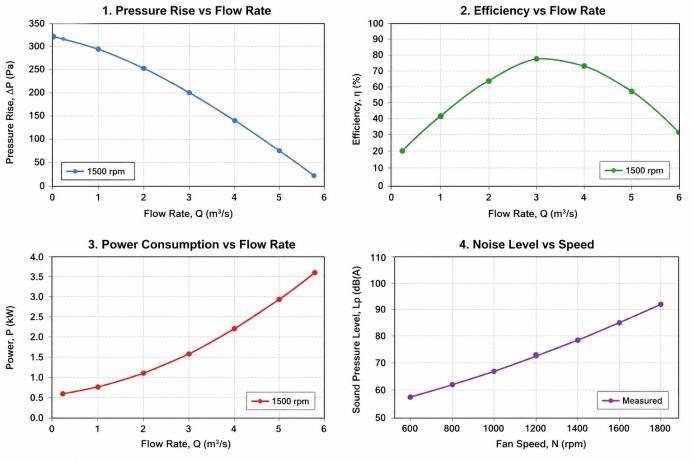
Fanperformanceisrepresentation
Pressurerisevsflowratecurve
Efficiencyvsflowratecurve
Powerconsumptionvsflowratecurve
Noiselevelvsspeedcurve
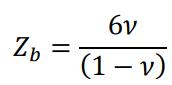
DTheHub-TipratioistheratioofHubdiametertothe overallfandiameter.Thehub-tipratiorangeofpropeller typeaxialflowfansislessthan0.3andthatofTube-axial andVane-axialfanisbetween0.3and0.5
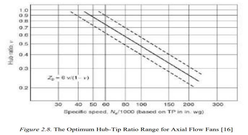
Fig -3: The optimum hub-tip ratio for Axial flow fan.
Theclearancevolumebetweenbladetipandcasingwallis the Tip Clearance. Leakage flows through this creating vortexandreducingefficiency.Lowertipclearancegenerally improvesperformance.
Fan speed strongly affects pressure rise, power consumption,andnoise.Higherspeedincreasesairflowbut alsoincreasesacousticemissionsandenergydemand.
Axialflowfanperformanceisgovernedbytheconservation equationsofthefluidflow.IntheCFD-baseddesign,these equationsaresupposedlysolvednumericallytopredictthe aerodynamicperformance.
2. 1 Blade geometry
Blade geometry is a important factor in designing. Chord length, camber, thickness, pitch angle, stagger angle, and blade twist are the parameters which strongly influence aerodynamicbehavior Agoodbladedesignresultsinsmooth flowandsuffersminimumlosses.
2. 2 Number of Blade
Increaseinbladecountimprovesinpressuredifference,But toomuchbladecountincreaseblockage,frictionlosses,and Tonalnoises.Anoptimizedbladenumbershouldbefinalized consideringabovedrawbacks.
3.1 Continuity Equation (Mass Conservation)
Foranincompressibleflow:

Thisensuresthatmassisconservedwithintheflowdomain.
3.2 Momentum Equation (Navier–Stokes Equation)
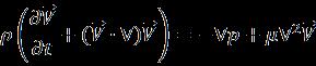
Where: =density =velocityvector
International Research Journal of Engineering and Technology (IRJET) e-ISSN: 2395-0056
Volume: 13 Issue: 05 | May 2026 www.irjet.net p-ISSN: 2395-0072
=pressure = dynamicviscosity
Thisequationgovernsthe pressuregenerationandvelocity distributioninaxialfans.

Where:
=bladevelocity

=whirlcomponentofthevelocity
This equation explains how the rotational energy is convertedintoincreaseinpressure. These governing equations are based on standard turbomachinerytheory[4]
ComputationalFluidDynamicsisoneoftheimportanttool present in today’s time for fan development. CFD solves governingequationsoffluidflownumericallyandpredicts internal aerodynamic behavior[3] without repeated experiments.
Modern CFD softwares can estimate:
Velocitycontours
Pressuredistribution
Turbulenceintensity
Wakeformation
Tipleakagevortices
Flowseparationzones
Overallefficiency
InrecentyearsitisfoundthatthatresultsprovidedbyCFD models are very close to that of experimental results. CommonTurbulencemodelsusedareasfollows:
Standardk-epsilonmodel
RNGk-epsilonmodel
K-OmegaSSTmodel
ReynoldsStressModel
AmongthesetheK-OmegaSSTmodelispreferredduetoits nearwallbehaviourandseparationresultsareaccurate. DuetoCFDEngineersnowcantestmanychangesindesign like blade angle, blade count, and casing geometry before manufacturingaprototype.
Recent research has been focusing on improving fan performancethroughoptimizationtechniques.
Improper blade angle may cause flow separation and reduced pressure rise. Numerical studies directs to that moderate stagger angles may provide better balance betweenairflowandefficiency.
5.2
Winglets attached to near blade tips may help reduce leakagevortices.Thesefeaturescanimproveaerodynamic efficiencyandlowernoiselevels.
5.3
Moderndesignersoftenoptimizemorethanoneparameter, suchas:
Lowerpowerconsumption
Maximumefficiency
Minimumnoise
Desiredpressurerise
Geneticalgorithmsandresponsesurfacemethodssuggested commonlyused[2],[3]forsuchproblems.
5 4 AI – Based design
Machine learning methods are said to being increasingly usedtopredictperformancefromhistoricaldesigndata.This reducescomputationaltimecomparedtorepeatedCFDruns.
6. Guide Vanes and Flow Recovery
Guide vanes are supposedly said to be stationary blades placedbeforeoraftertherotatingimpeller.
Inlet Guide Vanes
Thesevanesaretheretocontrolthedirectionofincoming airandimprovetheincidenceangleattherotor.
Outlet Guide Vanes
These are useful for removing swirl energy and then convertingitintousefulstaticpressure.
Studies supposedly shows that vane number, vane angle, spacing, and chord length can significantly affect the final performance. Poor vane design may create additional turbulence, while the optimized vanes may improve pressurerecoveryanduniformity.
Guidevanesareparticularlyusefulinindustrialventilation systemswherethe higherstaticpressureisrequired.
Guidevanes effectsis extensivelystudiedintheliterature [1].
Noise control is said to be becoming a major design requirement,MostlyinHVACsystems,offices,datacentres, andhouseholdappliances.
Fannoiseismainlygeneratedby:
Bladepassingthefrequencytones
Tipvortexinteraction
Turbulenttrailingedgenoise
International Research Journal of Engineering and Technology (IRJET) e-ISSN: 2395-0056
Volume: 13 Issue: 05 | May 2026 www.irjet.net p-ISSN: 2395-0072
Flowseparationatoff-designconditions
Mechanicalimbalance
Proposedmethodstoreducethe fannoiseinclude:
Optimizedbladespacing
Serratedtrailingedges
Lowertipclearance
Smoothbladeloading
Reducedrotationalspeed
Bettercasingdesign
RecentCFD-acousticcouplingmethodsarehelpingidentify majorsoundsourcesduring[6]earlydesignstages.
A recent study done by Fanbao Chen et al.[1] applied the combined CFD and DOE to optimize the guide-vane parametersinanaxial flowfan.The results thatthevane chordlengthhad,hasthelargestsignificantinfluenceonthe airflowsimulations,Thevanenumberhadasecondaryeffect
But by reducing the vane chord length by 38 mm and changing vane number to 18, the system had said to achieved an optimized flow rate of 142.07 m³/h at 5000 rpm. This CFD model was then validated against the experimentalmeasurements,revealingthe closeagreement withlessthan5%deviation.ThisshowsthattheCFD-driven optimization can really decrease the need for physical prototypes,testingandaccelerating thedesignprocess
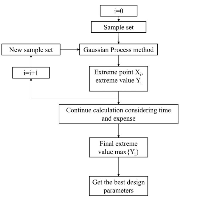
Fig -3:ExtremepointsearchmethodforGuidevane number[1]
A CFD optimization study done Renhui Liu et al.[3] investigated the influence of these structural parameters suchasbladeinstallationangle,numberofblades,deflector configuration, and rotational speed on the aerodynamic
performanceofanaxialflowfan.Thisstudyhasutilizedthe numericalsimulationstogeneratethepressure-flow(P–Q) characteristics and analyse velocity and pressure distributionsmade insidethefan.
Theresultshadshowedthatthe fanperformanceishighly reactive to the blade installation angle and the rotational speed. Within the range considered, the optimal design configurationtoimproveairflowcharacteristicsandoverall efficiencywasidentified.Thisfurtherdemonstratedthatthe CFD approach is capable of estimating performance parameterssuchaspressurerise,flowrate,andefficiency withoutcostlyexperimentalmeasurements.
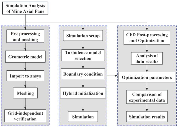
Theoptimizationworkflow,involvingfinitevolumeanalysis and iterative simulations, virtually evaluated hundreds of designs. The grid independence study showed that the simulation's accuracy wasmaintained within a very small errorbandofabout0.5%.
This adds more weight to the reliability of this computational approach. This confirms that a CFD-based design process quickly evaluates a wide range of design variables, drastically reduces the need for physical prototyping, and thus becomes a significant part of contemporaryfandesigndevelopment.
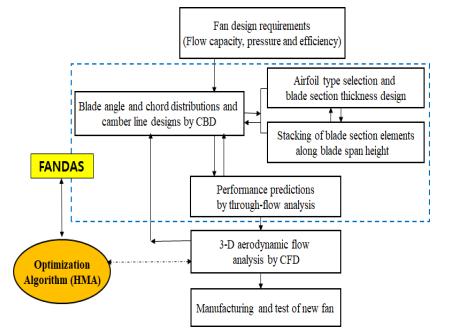
8.3 Hybrid Optimization using Through-Flow Model, CFD and FANDAS (2025)
Recentlyin2025,theauthorsproposedanadvanceddesign methodology that would allow efficient design of highperformance axial fans based on CBD, through-flow modeling, and CFD combined with hybrid optimization algorithms.
Alargenumberofdesignvariables,suchascamberangle, settingangle,andchordlengthdistributionalongthespan, wereconsidered.Toautomatetheexplorationofthedesign
International Research Journal of Engineering and Technology (IRJET) e-ISSN: 2395-0056
Volume: 13 Issue: 05 | May 2026 www.irjet.net p-ISSN: 2395-0072
space, a metaheuristic algorithm was embedded in the FANDASdesignprogram
Theoptimizedfanshowedanincreaseinefficiencybyabout 4.2%comparedtotheinitialdesign.Toverifythemodel,the CFD results were compared with experimental results. It showedexcellentpredictiveaccuracy.Hence,thisindicates thatthemethodologyusedtoestimatetheperformanceof fansbeforetheirphysicalmanufacturingishighlyreliable. Inaddition,ithasbeenshownthatthrough-flowmodeling combined with CFD is efficient in terms of reducing the computationaleffortwhilemaintaininghighaccuracyinthis study.
Hence, this hybrid approach will allow more rapid optimization than a fully CFD-based approach and can be handledundermultipledesignconstraints. Thisstudyhas further demonstrated that using CFD-based optimization algorithmscombinedwithreduced-ordermodelscanrapidly design without depending too heavily on physical prototypes.
Axial flow fans are the fans widely used across various industrial, commercial, and domestic applications due to theirabilitytodeliverlargevolumesofairwithlowpressure and smaller design. Their simple construction, high efficiency,andadaptabilitymakesthemthe oneofthemost sought-out for air-movingdevicesinhistoryofengineering systems.
In industrial environments, the axial fans are extensively usedfor theventilation,cooling,andexhaustsystem usecases. They are said to be commonly installed in the factories, workshops, and process plants to remove heat, fumes,dust,andToxicgasesovertime.Inthepowerplants and the boilers, axial fans can assist in maintaining the airflowforcombustionandcoolingsystems.Coolingtowers
also supposedly rely heavily on axial fans to enhance the heat dissipation by increasing the airflow across water surfaces.
The Axial flow fans plays a critical role in the large-scale infrastructure operations such as tunnels, subways, and mining.Inthetunnelventilationsystems,theyaresupposed tosupplyfreshairandremovetheexhaustgases,especially during allfireemergencies.Inthe undergroundmines,axial fanshavesaidtoensuredacontinuoussupplyofbreathable oxygenandremovingtheharmfulgasesanddustparticles, improvingthe workersafetyandoperationalefficiency.
In the heating, ventilation, and air-conditioning (HVAC) systems,axialfansare beenusedintheairhandlingunits, the ventilation ducts, and the exhaust systems. They had helped regulateindoorairquality indexbycirculating the fresh air and removing all of the stale air. In large scale commercialbuildingssuchasmalls,hospitals,andtheoffice complexes, axial fans have contributed to maintaining thermalcomfortandproperairdistribution.
Small axial fans are widely been used in the electronic cooling applications. Devices like the computers, servers, telecommunications equipment, and power electronics generates significant heat during its operation. Axial fans helpsmaintainthesafeoperatingtemperaturesbyremoving theheatfromallsensitivecomponents.Inthedatacentres, high-performanceaxialfansarebeenusedtoensureefficient airflowmanagementandpreventoverheating.
IntheAutomotivesector,axial fans havebeenusedinthe radiator cooling systems, and cabin ventilation systems. Withthegrowingadoptionoftheelectricvehicles,axialfans arebeingusedinbatterythermalmanagementsystemsto regulatethetemperatureandimprovebatteryperformance anditslifespan.
Axial fans are also being used in the agriculture for the greenhouseventilation,graindrying,andlivestockcooling. Proper air circulation helps maintain the Proper environmentalconditionsforthecrop’s growthandanimal’s health. They are also used in the air pollution control systems to manage the airflow in filtration and exhaust setups.
This paper has reviewed the recent shift in the design of axialflowfansfromtheempirical,conventionalmethodsto thesimulation-basedapproaches.TheConventionaldesign methods involved multiple iterations of prototyping and
International Research Journal of Engineering and Technology (IRJET) e-ISSN: 2395-0056
Volume: 13 Issue: 05 | May 2026 www.irjet.net p-ISSN: 2395-0072
experimentaltesting,whichincreasedthetimeandcostof development.However,developmentsincomputationalfluid dynamics (CFD), design of experiments (DOE), and optimizationtechniquesnowallowfanstobevirtuallytested andoptimizedbeforemanufacture.
In most recent research, the most important variables affectingthevolumetricflowrate,pressurerise,efficiency, and noise generation of axial fans were the blade angle, guidevaneshape,androtationalspeed.UsingaCFDmodel with an appropriate turbulence model and properly gridindependent checked, one can predict the aerodynamic performancewithgreataccuracyandcloseagreementwith theexperimentalresults.
Indeed,theapplicationofdifferentoptimizationtechniques such as DOE, Gaussian process modeling, gradient-based methods,orhybridcomputationalframeworksallowsdesign spaces to be explored efficiently. In this way, multiple parameters can be optimized simultaneously, leading to certain improvements in performance and efficiency compared with the initially proposed design and greatly reducingthenumberofiterationsduringthedesignprocess. Another important result of the studies reviewed is the significantdecreaseintheneedforphysicalprototypingof thedesigns.DuetothecapabilitiesofCFDandoptimization algorithms,itispossibletoanalyzeseveraldesignvariants before their realization, thus considerably reducing the number of prototypes and shortening the entire developmenttime.Inotherwords,simulation-drivendesign reducescostsandincreasesthereliabilityandrepeatability oftheworkflow.
Therefore,currentdesignsofaxialflowfansrelyheavilyon integrated computational frameworks that involve CFD simulations,data-drivenoptimization,andstate-of-the-art modelingtechniques.Lookingintothefuture,suchaprocess will be enhanced further by introducing artificial intelligence, digital twins, and advanced manufacturing methodstoproducelow-noise,efficient,andgreenfans.
[1] F. Chen, G. Zhu, D. Xi, and B. Miao, “Airvolumeflowrateoptimizationofguidevanesinan axial flow fan based on DOE and CFD,” ScientificReports,vol.13,2023.DOI:https://doi.org/10.10 38/s41598-023-31666-w
[2] C. Lee, S. W. Kim, H. T. Byun, and S. H. Yang, “High-efficiency axial flow fan design by combining through-flow modeling, optimization algorithm and computational fluid dynamics simulation,” Journal of Applied Fluid Mechanics, vol. 18, no. 8, pp. 19531963,2025.DOI:https://doi.org/10.47176/jafm.18. 8.3325 R. Nicole, “Title of paper with only first word capitalized,”J.NameStand.Abbrev.,inpress.
[3] KR.Liu,S.Xu,K.Sun,X.Ju,W.Zhang,W.Wang,X.Ma,Y. Pan,andJ.Li,“CFDanalysisandoptimizationofaxialflow fans,”International Journal of Simulation and Multidisciplinary Design Optimization, vol. 15, 2024. DOI:https://doi.org/10.1051/smdo/2024007
[4] H.Cohen,G.F.C.Rogers,andH.I.H.Saravanamuttoo, GasTurbineTheory,6thed.,PearsonEducation,2009.
[5] MustafaTutarandJansetBetuCam,“ComputationalDesign of an Energy-Efficient Small Axial-Flow Fan Using StaggeredBladeswithWinglets,”InternationalJournalof Turbomachinery,PropulsionandPower,vol.10,2025. DOI:https://doi.org/10.3390/ijtpp10010001
[6] Yaming Fan, Linwei Yu, Jinchai Shen, Yiyu Li, Minfeng Zheng,andShermanC.P.Cheung,“Optimizationofaerodyna mic performance and aeroacoustic characteristics in axial flow fans for direct evaporative air conditioning systems,”Engineering Applications of Computational Fluid Mechanics, vol. 19, no. 1, 2025, Article ID: 2569645.DOI:https://doi.org/10.1080/19942060.2025. 2569645