
International Research Journal of Engineering and Technology (IRJET) e-ISSN: 2395-0056
Volume: 12 Issue: 10 | Oct 2025 www.irjet.net p-ISSN: 2395-0072
International Research Journal of Engineering and Technology (IRJET) e-ISSN: 2395-0056
Volume: 12 Issue: 10 | Oct 2025 www.irjet.net p-ISSN: 2395-0072
Toheed Ameen Mujawar1, Parasharam Sawant2
1 Post Graduate Scholar, Dept of Civil Engineering, S. G. Balekundri Institute of Technology, Belagavi, Visveshvaraya Technological University, Belagavi Karnataka, India 590010
2 Assistant Professor, Dept of Civil Engineering, S. G. Balekundri Institute of Technology, Belagavi Visveshvaraya Technological University, Belagavi Karnataka, India 590010
Abstract - Cold-formedsteel(CFS)combinesalightweight nature with superior load-bearing capability, making it a preferred choice for modern structural applications. This study utilizes finite element analysis through ANSYS to investigate the behavior of built-up CFS members specifically back-to-back (B2B) and back-to-back with lip stiffener (B2B+C1) arrangements developed in accordancewithAISIspecifications.Accuratemeshingand controlledloadingconditionswereappliedtosimulateboth axial and bending responses, allowing for precise observation of stress distribution and deformation characteristics.Thecomparativestudyrevealsthatthelipstiffenedmodelachievesarounda15%increaseinultimate capacitywhilereducingdeflection.Thesefindingsprovide valuableinsightsforrefineddesignpractices,enhancingthe performanceanddependabilityofCFSsystemsinstructural engineering.
Key Words: Built-UpSections,ANSYS,AISIStandards,ColdFormed Steel, Finite Element Analysis, Back-to-Back Configuration, Stress Distribution, Deformation Analysis, StructuralOptimization
Cold-formedsteel(CFS)hasseensignificantadoptioninthe construction industry due to its distinct benefits over conventional materials. Its light weight, high strength-toweightratio,costefficiency, andlong-lastingperformance make it a preferred choice for various structural applications. CFS sections are generally slender, with thicknesses ranging from about 0.75 mm to 4 mm, and commonly exhibit yield strengths between 230 MPa and 340 MPa. To enhance their corrosion resistance, these sectionsareoftencoatedwithzincorzinc–aluminumalloys.
In most applications, CFS serves as secondary structural componentssuchasroofpurlins,siderails,partitionstuds, andwallcladdings.Thesemembersaretypicallyjoinedusing screws, bolts, rivets, or specially designed fasteners. The performance of the structure is heavily influenced by the selectionandlayoutoftheseconnectors,astheyfacilitatethe transferofloadsandmomentsbetweenprimaryframingand supportelements.Incertaincases,supplementarystiffeners orspecializedconnectionsareincorporatedtooptimizeload transfer.
This analytical study focuses on evaluating the structural behavior of built-up CFS columns and beams under combinedthermalandmechanicalloads.Unlikehot-rolled steel,CFS is producedatambienttemperature byshaping thin steel strips or sheets into specified profiles without applying external heat. Manufacturing processes, such as continuousrollformingorpressbraking,areusedtocreate lipped channels (C-sections), Z-sections, angles, and other advancedbuilt-upsectionprofiles
Cold-formed steel (CFS) is produced by mechanically shaping thin steel sheets into specific profiles at ambient temperature.Unlikethehot-rollingprocess,whichrequires high-temperature deformation above the recrystallization point,coldformingretainstheoriginalmicrostructureofthe steel, resulting in distinct mechanical and geometric advantages.Thesecharacteristicsinclude:
Lowself-weight
Highstrength-to-densityratio
Excellentdimensionalaccuracy
Smoothanduniformsurfacefinish
Built-up sections are formed by connecting two or more cold-formed steel (CFS) profiles commonly channel sections usingscrews,bolts,orweldssothattheyfunction as a unified structural element. This assembly enhances overall strength, stiffness, and stability compared to individual members. In column applications, channels are typicallyjoinedeitherback-to-backorface-to-face,whilein beams,lippedchannelsarespacedandfastenedtogetherto effectivelyresistbendingforces.
Thestructuralresponseofbuilt-upCFSmembersislargely influencedbythedetailingoftheirconnections,including:
Screwspacing
Numberofscrewsperunitlength
Edgedistancefromscrewlines
Staggeredoralignedscrewlayout
International Research Journal of Engineering and Technology (IRJET) e-ISSN: 2395-0056
Volume: 12 Issue: 10 | Oct 2025 www.irjet.net p-ISSN: 2395-0072
Toevaluatethestructuralperformanceandbuckling behaviorofbuilt-upcold-formedsteelsectionsunder axialloadingusingfiniteelementanalysisinANSYS.
Toexaminetheeffectsofgeometricparameters,such asscrewspacingandconnectiontypes,onthestability andload-carryingcapacityofcold-formedsteelbuiltupcolumns.
To establish reliable design criteria and propose optimizationstrategiesforcold-formedsteelbuilt-up members that improve safety, efficiency, and economicfeasibilityinmodernconstructionpractices.
This research presents a detailed finite element study of built-up cold-formed steel (CFS) sections subjected to combinedstaticandthermalloads.Differentconfigurations, including back-to-back and stiffened assemblies, were precisely modelled with accurate geometry and material properties using SolidWorks and ANSYS. Simulations incorporated linear elastic behaviour and fixed boundary conditions to reflect real structural scenarios. Loading conditions considered axial compression, bending, temperature increases, and varying screw spacing’s to evaluateconnectioneffects.Criticalregionswerecarefully meshed to ensure result accuracy, and both linear and nonlinearbucklinganalyseswereperformedtodetermine failure points and load limits. The models were validated through comparisons with experimental data and design standards. Parametric investigations demonstrated how design choices, screw arrangements, and thermal factors influence strength, stiffness, and stability, providing practical insights for optimizing CFS built-up members in lightweightsteelconstruction
Thestudyinvestigatesthestructuralperformanceofcoldformedsteel(CFS)built-upmembers,focusingonback-toback (B2B) and back-to-back with lip stiffener (B2B+C1) sections under axial and thermo-mechanical loads. The analyzedsections 350S162-43,400S162-43,550S162-43, and 600S162-43 were modeled with defined geometric parameterssuchaswebheight,flangewidth,lipsize,and thickness.ConsistentmaterialpropertiesincludingYoung’s modulus,yieldstrength,anddensitywereused to ensure realisticsimulations.
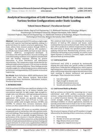
Stress-strain curves indicated that smaller profiles like 350S162-43and400S162-43achievedhigherstresslevels across all strain ranges, showing superior load-carrying abilitycomparedtothelarger550S162-43and600S162-43 sections.Deformationresultsdemonstratedthatlarger
sections undergo greater deflection, with 600S162-43 showingthehighestand350S162-43theleastdeformation.
Introducing lip stiffeners in the B2B+C1 configuration significantlyenhancedperformancebyreducingdeflection andincreasingultimatestrengthbynearly15%,provingthe benefitofstiffeningelementsinimprovingsectionstability. Theanalysisfurtherrevealedthatvaryingscrewspacing particularlybetween12-inchand24-inchconfigurations affected stress distribution and deformation patterns, highlighting the role of fastener arrangement in member performanceandbucklingresistance.
Overall, the research provides meaningful insights into efficientCFSmemberdesign,emphasizingtheimportanceof sectiongeometry,stiffening,andconnectiondetailing.The predicted stress, strain, and deformation patterns aid in developing safer and more economical lightweight steel structuressuitedformodernconstructionpractices
Table 1. Comparison between Sections
43
43
Unit: The pound per square inch (abbreviation: psi)

Fig 1. Comparison between Different Sections respective to its strength Strain (mm/mm)
International Research Journal of Engineering and Technology (IRJET) e-ISSN: 2395-0056
Volume: 12 Issue: 10 | Oct 2025 www.irjet.net p-ISSN: 2395-0072
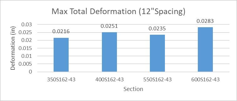
Fig 2. Graphical Representation of Deformation Comparison between Sections
4.2. COMPARISON BETWEEN SECTIONS 24” SPACING BACK TO BACK SECTIONS
Table 2. Comparison between 24” Spacing Back to Back Sections
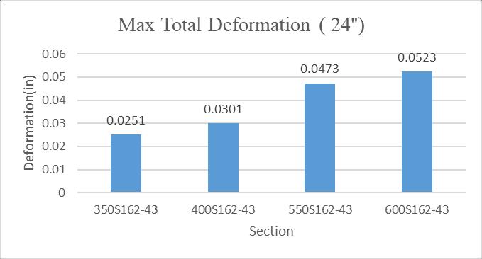
Fig 4. Graphical Representation of Deformation Comparison between 24” Spacing Back to Back Sections
4.3. COMPARISON BETWEEN SECTIONS 12” SPACING BACK TO BACK + C1 SECTIONS
Table 3. Comparison between 12” Spacing Back to Back+C1 Sections
Unit: The pound per square inch (abbreviation: psi) Strain (mm/mm)
Unit: The pound per square inch (abbreviation: psi)
Fig 3. Comparison between 24” Spacing Back to Back Sections
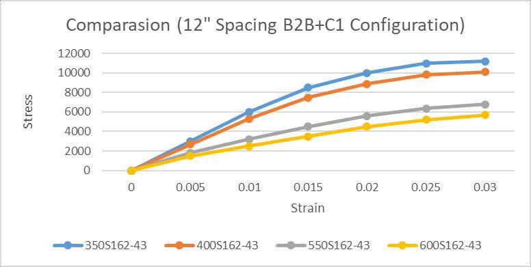
Fig 5. Comparison between 12” Spacing Back to Back+C1 Sections
International Research Journal of Engineering and Technology (IRJET) e-ISSN: 2395-0056
Volume: 12 Issue: 10 | Oct 2025 www.irjet.net p-ISSN: 2395-0072
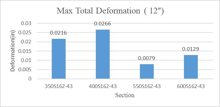
Fig 6. Graphical Representation of Deformation
Comparison between 12” Spacing Back to Back+C1 Sections
4.4. COMPARISON BETWEEN SECTIONS 24” SPACING BACK TO BACK + C1 SECTIONS
Table 4. Comparison between 24” Spacing Back to Back+C1 Sections
Strain (mm/mm)
43
43
43
0.005 2800 2660 2340 2100
0.01 5800 5300 3800 3300
0.015 7900 7280 5420 4800
0.02 9700 8920 6580 5800
0.025 10500 9840 7860 6500
0.03 9936 9388 7747 7200
Unit: The pound per square inch (abbreviation: psi)
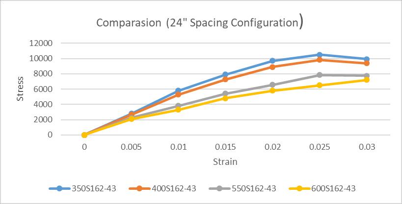
Fig 7. Comparison between 24” Spacing Back to Back+C1 Sections
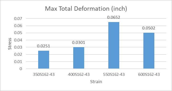
Fig 8. Graphical Representation of Deformation Comparison between 24” Spacing Back to Back+C1 Sections
This study conducted a detailed analysis of cold-formed steel (CFS) built-up columns with different section types under static and combined thermal loads. Using finite elementmodelinginANSYS,itwasfoundthatback-to-back built-up sections equipped with lip stiffeners notably improvedstructuralcapacitybyabout15%anddecreased overalldeflections.Theseperformancegainsarelargelydue to the careful optimization of connection details such as screw spacing, which play a critical role in enhancing stabilityandpreventingbuckling.Thetestsindicatedthat smaller section profiles have greater load capacity and experience less deformation, making them more effective for structural use in demanding applications. The results contribute valuable guidance for improving design and constructionmethodsforCFSbuilt-upmembers,promoting their efficient, safe, and cost-effective use in modern lightweightsteelconstruction.
The authors want to express sincere gratitude to Prof. Parasharam Sawant, an assistant professor in the S.G. Balekundri Institute of Technology Department of Civil Engineering, Guide, PG Coordinator for his unwavering support and direction during this project report. Additionally, I am appreciative of the helpful advice and supportprovidedby Dr. Santosh Chikkabagewadi,Headof Department, The authors thank Dr. B. R. Patagundi Principal,S.G.BalekundriInstituteofTechnologyforallthe help and encouragement given during the project report. Theauthorswouldliketothank Dr. F. V. Manvi Chairmanof S.G.BalekundriInstituteof Technology,for theirsupport. Also, the authors thank all the staff of Civil Engineering Departmentandalsotothank myparents,andfriendsfor theirencouragementthroughoutthisproject.
[1]. El Aghoury, M., Tawfic, M., & Amoush, E. (2020). Compressivestrengthofaxiallyloadedbuilt-upSigma
International Research Journal of Engineering and Technology (IRJET) e-ISSN: 2395-0056
Cold formed sections columns. Future Eng. J, 1, 23147237.
[2]. Selvaraj,S.,&Madhavan,M.(2018).Cold-formedsteel built of columns: Experimental investigation. InProc., 9thInt.Conf.onAdvancesinSteelStructures,editedby SLChan,TMChan,andS.Zhu.HongKong:HongKong Institute of Steel Construction. https://doi. org/10.18057/ICASS2018(p.168).
[3]. Zhou,T.,Li,Y.,Wu,H.,Lu,Y.,&Ren,L.(2020).Analysis to determine flexural buckling of cold-formed steel built-up back-to-back section columns.Journal of ConstructionalSteelResearch,166,105898
[4]. Kaleeswaran,C.,Saravanakumar,R.,Vivek,D.,Elango,K. S.,Gopi,R.,&Balaji,D.(2021).Astudyoncoldformed steelcompressionmember-areview.MaterialsToday: Proceedings,37,1767-1771
[5]. Senthilkumar,R.,Divya,M.,DivyaRoy,S.,&Bahurudeen, A. (2022, October). Behaviour of cold-formed steelconcretecompositecolumnsunderaxialcompression: Experimental and numerical study. InStructures(Vol. 44,pp.487-502).Elsevier.
[6]. Chen,M.,Shen,K.,Lu,W.B.,Zhang,X.Y.,Shi,Y.,Yang,C. F.,&Wang,H.L.(2023,July).Compressiontestsofcoldformed steel built-up T-shaped columns. InStructures(Vol.53,pp.1172-1185).Elsevier.
[7]. Georgieva,I.,Schueremans,L.,Vandewalle,L.,&Pyl,L. (2012). Design of built-up cold-formed steel columns according to the direct strength method.Procedia Engineering,40,119-124.
[8]. Salokhe, S. A., Chavan, S. P., & Kumbhar, Y. D. ExperimentalAndAnalyticalStudyOfBehaviorOfLight GaugeSteelColumnSection.
[9]. Gaikwad, S. S., & Salgar, P. (2020). Finite Element AnalysisOnBackToBackChannelGappedColdFormed BuiltUpSection.
[10]. Ellobody,E.,&Young,B.(2005).Behaviorofcoldformedsteelplainanglecolumns.JournalofStructural Engineering,131(3),457-466.
[11]. Veeraiyan,C.,&Karthikeyan,S.(2019).Behaviourof Cold Formed Steel Built-up Columns by Using Fasteners.Behaviour,6(04).
[12]. Craveiro,H.D.,Rodrigues,J.P.C.,&Laím,L.(2016). Bucklingresistanceofaxiallyloadedcold-formedsteel columns.Thin-WalledStructures,106,358-375.

Volume: 12 Issue: 10 | Oct 2025 www.irjet.net p-ISSN: 2395-0072 © 2025, IRJET | Impact Factor value: 8.315 | ISO 9001:2008
Er. Toheed Ameen Mujawar
PostGraduateScholar,DeptofCivil Engineering, S. G. Balekundri Institute of Technology, Belagavi, Visveshvaraya Technological University, Belagavi Karnataka, India

Prof. Parasharam Sawant
Assistant Professor, Dept of Civil Engineering, S. G Balekundri Institute of Technology, Belagavi Visveshvaraya Technological University, Belagavi Karnataka, India