
International Research Journal of Engineering and Technology (IRJET) e-ISSN: 2395-0056
Volume: 13 Issue: 03 | Mar 2026 www.irjet.net p-ISSN: 2395-0072
International Research Journal of Engineering and Technology (IRJET) e-ISSN: 2395-0056
Volume: 13 Issue: 03 | Mar 2026 www.irjet.net p-ISSN: 2395-0072
Tanmay Kulkarni1 , Purvesh Meher2 , Hardik Joshi3 , Jeevan Mane4, Prof. Mayur Suryawanshi5
1,2,3,4 Students, Dept of Civil Engineering, G.V Acharya Institute of Engineering & Technology, Karjat, Maharashtra, INDIA.
5 Professor, Dept. of Civil Engineering, G.V Acharya Institute of Engineering & Technology, Karjat, Maharashtra, INDIA
Abstract - The RCC buildings have to withstand manytypes of loads, including seismic and wind loads. In this project, we have carried out an analysis on a G+11 RCC building using ETABS software while taking into consideration seismic and wind loads. In this analysis, we have also used Response Spectrum Analysis as per IS:1893-2016 and Wind Load Analysis as per IS:875-2015. Shear walls werealsoprovided to enhance lateral resistance in the building. Also, P-Delta analysis was carried out on the building model As per the analysis results, it is seen that the displacement in thebuilding remains within limits. The addition of shear walls in the building model has significantly increaseditsstiffness, whilein P-Delta analysis, there is an increase in displacement in the building model.
Key Words: AutoCAD, E-Tabs, Analysis, Seismic Analysis, Civil Engineering, Structural Engineering, P-Delta
RCCbuildingsarewidelyusedinconstructionbecausethey arestrong,durableandalsoeconomicalcomparedtoother systems.Duetoincreaseinpopulationanddevelopmentof cities, multi-storey buildings are being constructed more frequently. For such buildings, it becomes important to ensurethattheyaresafeunderdifferenttypesofloads.
Apartfromnormaldeadloadandliveload,buildingsarealso subjectedtolateralloadslikeearthquakeandwind.These loadsarenotalwaysvisiblebuttheycanhaveamajoreffect onthe structure, especiallyintaller buildings. If theseare not considered properly during design, it may lead to excessivemovementorevenfailureinsomecases.
InIndia,differentstandardcodesareusedforanalysisand design of RCC structures. IS 456:2000 is used for general design of concrete members, IS 1893:2016 is used for earthquake analysis, and IS 875 is used for calculating differentloadsincludingwindload.
These codes help in maintaining safety and uniformity in design.Inthiswork,aG+11RCCbuildingis modelledand analysedusingETABSsoftwarebyconsideringseismicand windeffects.
Shear walls are provided to improve stability of the structure,andP-Delta analysisisalsocarriedouttostudy additional effects due to deformation. The purpose of this studyistounderstandthebehaviourofthebuildingandto checkwhetheritsatisfiesthebasicsafetyrequirements.
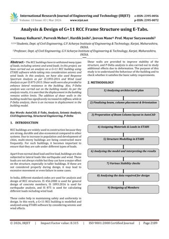
2. METHODOLOGY
1) Analyzing architectural plan
2) Finalizing beam, column placement & Orientation
3) Preparation of Beam Column layout in AutoCAD
4) Assigning Materials & Loads in ETABS
5) Structure Modelling in ETABS
6) Analyzing the model and interpreting the results
7) Various Stability checks
8) Analyzing the data required for design
9) Designing of Members
International Research Journal of Engineering and Technology (IRJET) e-ISSN: 2395-0056
Volume: 13 Issue: 03 | Mar 2026 www.irjet.net p-ISSN: 2395-0072
2.1. Analyzing architectural plan:
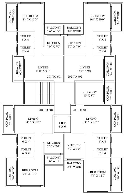
1: Floorplan.
Basic Details:
1)Typeofstructure:Residentialbuilding
2)PlanDimensions:13.5m*21.03m
3)NoofFloors:G+11
4)Floortofloorheight:3.2m
5)Canopy:Yes
6)AccessibleRoof:Yes
7)ShearWall:Yes
8)Location:Mumbai
9)SoilType:II
10)SeismicZone:III
11)DuctileDesigningRequired:Yes
12)CantileverBalcony:Yes
13)TotalHeightofthebuilding:44.8m
2.2. Finalizing beam, column placement & orientation:
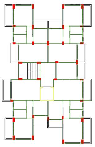
2: Beam,Column&Shearwallplacement
NOTE: Sizes of column shown in the line plan do not represent the actual size of column they placed just to represent the position of column & not the size
Beam, Column and Shear wall line layout is drafted using AutoCAD&afterthat,itisimportedinE-tabsfordesigning
Table 1: MemberDimensions
International Research Journal of Engineering and Technology (IRJET) e-ISSN: 2395-0056
Volume: 13 Issue: 03 | Mar 2026 www.irjet.net p-ISSN: 2395-0072
2.3 Preparation of Beam Column layout in AutoCAD:
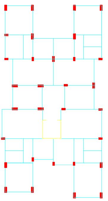
3: FinalBeam,Column&Shearwalllineplan
2.4. Assigning Materials & Loads in ETABS
A) Material Property:
Table 2: MaterialProperties
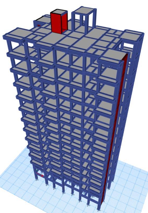
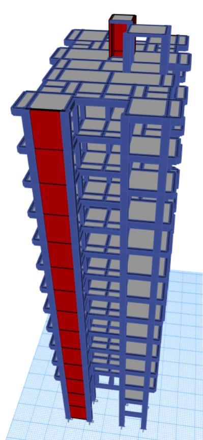
After assigning the materials, a 3d model is prepared in ETAB,inwhich1)StructuralelementslikeBeam,Column,
Slab,Shearwall,etc.isdesigned 2)LoadCombinationsare assignedwithreferencetorespectiveISCodes.
International Research Journal of
Volume: 13 Issue: 03 | Mar 2026 www.irjet.net
B) Loads:
a) Gravity Loads:
Table 3: GravityLoadValues
2kN/m²(Allrooms& Kitchens)+(Toilet& Bathrooms)
3kN/m²(Corridors, Passage&Balconies)
b) Earthquake Loads (Linear Static) (As per IS 1893:2016):
Table 4: EarthquakeLoadsData
International Research Journal of Engineering and Technology (IRJET) e-ISSN: 2395-0056
Volume: 13 Issue: 03 | Mar 2026 www.irjet.net
NOTE:Asperclause6.4.3,Equivalentstaticmethodmaybe usedforregularstructureswithapproximateNaturalTime Period(Ta)lessthan0.4s
AstimeperiodforEQ-X(0.832)andEQ-Y(1.061)isgreater than0.4s,“RESPONSESPECTRUMANALYSIS”isperformed.
c) Response Spectrum Analysis (Linear Dynamic):
AsResponseSpectrumAnalysisisperformed,thefirststepis toruntheanalysisandmatchthebaseshearbyscalingthe forbothRS-X&RX-Y.
RS-X:
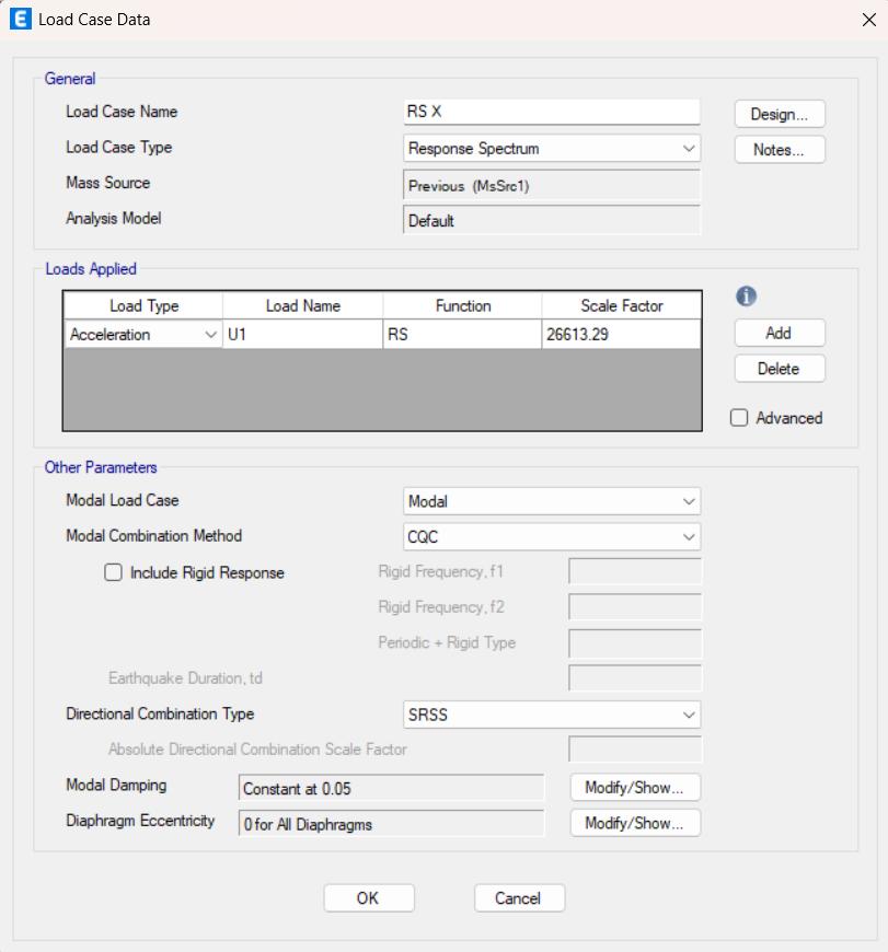
Figure 6: LoadCaseDataforRS-X
Basic Data:
Table 5: RS-XData Direction
Scale
RS-Y:
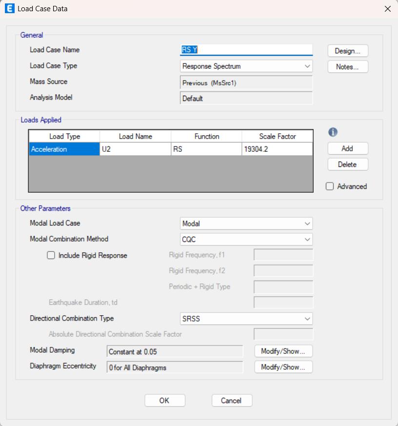
Figure 7: LoadCaseDataforRS-Y
Basic Data:
Direction
Table 6: RS-YData
U2(Ydirection)
ScaleFactor 19304.21
ModalLoadCase Modal
ModalCombinationMethod CQCMethod
DirectionalCombinationType SRSSMethod
DampingPercentage 5%
d) Wind Load:
WindLoadisperformedusingIS875PartIII:2015.
Basic Data:
Table 7: WindLoadsData
International Research Journal of
Volume: 13 Issue: 03 | Mar 2026 www.irjet.net
a) Defining Mass Source:
Mass source represents the seismic mass of the structure considered for dynamic analysis. It is calculated from the seismic weight, which includes full dead load and an appropriate percentage of imposed load as specified in IS 1893 (Part 1): 2016.Thismassisusedtodetermineinertia forcesduringearthquakeanalysis.
As per Clause 7.3.1: For various loading classes specified in IS 875 Part 2, design seismic force shall be estimated using full dead load plus percentage of imposed load
As per Table 10 of IS 1893 P1: 2016:
Table 8: Table10ofIS1893:2016(P1) Imposed
As per clause 7.3.2: For calculation of design seismic forces of buildings, imposed load on roof need not be considered
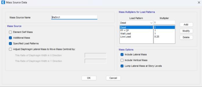
8: MassSourcedata
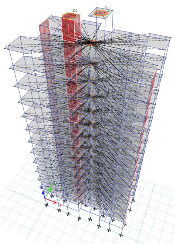
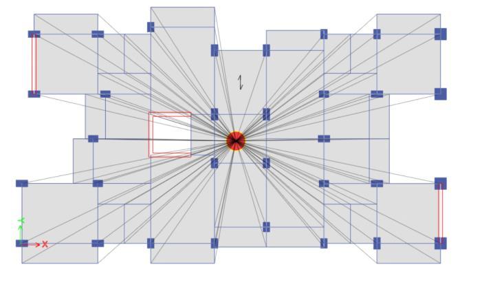
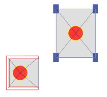
b) Diaphragm Assignment:
Diaphragmisahorizontalstructuralelement,suchasaslab, that transfers lateral loads to vertical resisting elements (columns,shearwalls).Itactsasarigidorsemi-rigidplate, ensuring uniform distribution of seismic forces in accordancewith IS 1893 (Part 1): 2016
BeforegoingforanalysisisE-tabsitismandatorytoassigna properdiaphragmforeachfloor Diaphragmareoftwotypes1)Rigid2)SemiRigid.
Inthisdesigningprocesswehaveused“RigidDiaphragm” .
International Research Journal of Engineering and Technology (IRJET) e-ISSN: 2395-0056
Volume: 13 Issue: 03 | Mar 2026 www.irjet.net p-ISSN: 2395-0072
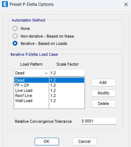
P–Delta effectisa second-order effect in whichadditional moments are generated in a structure due to axial loads actingonlaterallydisplacedmembers.Thiseffectbecomes significantintallandslenderstructuresandisconsideredin analysis.
P-Deltaanalysisismandatorywhenitcomestohighriseor irregularstructuresandevenforthestructureswhichare locatedinhighseismiczones.
Consideration of P-Delta in analysis gives more accurate resultswhichisveryimportantforsafestructuraldesigning.
Model check is the process of verifying the correctness, completeness, and stability of the analytical model before performing structural analysis. It ensures that geometry, materialproperties,connectivity,boundaryconditions,and load assignments are properly defined to obtain reliable results
In simple terms: “Model check ensures that the analytical model is error-free and suitable for accurate structural analysis”
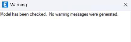
Figure 13: ModalCheckPassed
Model has been checked. Nowarningmessageweregenerated Hence the model is error free and is passed and we can proceedfortheanalysisstep.
2.6. Analyzing the model and interpreting the results:
AfteranalysisisperformedinEtabsvariousdataisobtained andcheckedsomeofthemareasfollows:
a) Deflection:
NOTE: Scale Factor for P-Delta is not explicitly mentioned anywhere in IS Codes, while designing engineers use the scale factor as per the designing needs and their own experience
Now, after modelling the structure it is very important to check whether all the members all passing the “Modal Check”
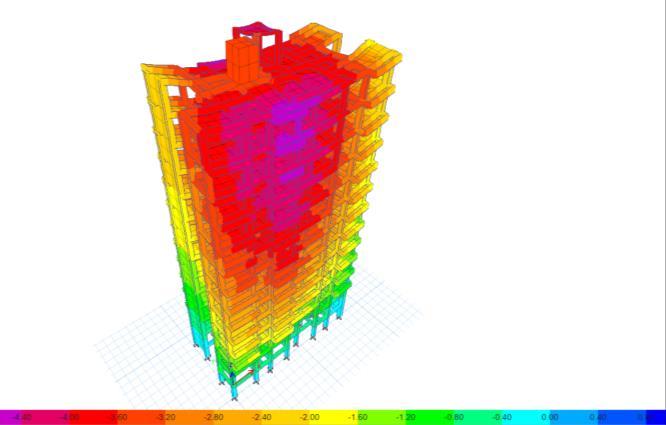
Figure 14: DeflectioninUZdirection
TheabovedeflectionreflectsdeflectioninUZdirectionalong withthemaximumdeflectionoccurringinthestructurei.e.,4.40mm. The deflection is checked using the unfactored loads.Asper IS 456:2000.
International Research Journal of Engineering and Technology (IRJET) e-ISSN: 2395-0056
Volume: 13 Issue: 03 | Mar 2026 www.irjet.net p-ISSN: 2395-0072
b) Maximum Storey Displacement:
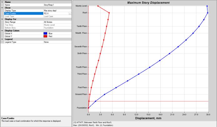
15: MaximumStoreyDisplacement(RS-X)
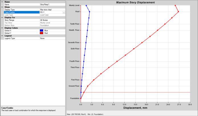
Figure 16: MaximumStoreyDisplacement(RS-Y)
Thedisplacementofthestructureincreasesgraduallyfrom base to top storey in both X and Y directions. Maximum displacementisobservedattherooflevel.Theoveralltrend showssmoothvariationalongtheheightofthebuilding.No suddenirregularityisobservedinthedisplacementprofile.
c) Maximum Storey Drift:
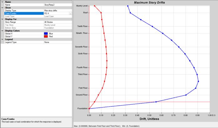
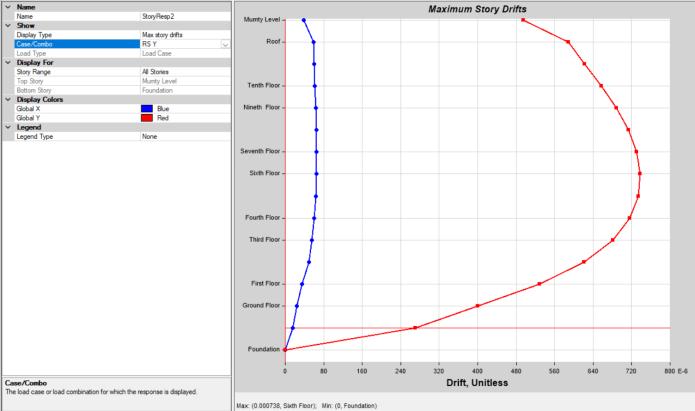
Thestoreydriftincreasesalongtheheightofthestructurein both X and Y directions, with maximum drift observed at upperstorey.Thevariation ofdriftissmoothwithoutany sudden irregularity. The drift profile indicates stable structuralbehaviorunderlateralloading.
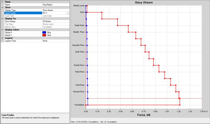
d) Storey Shear:
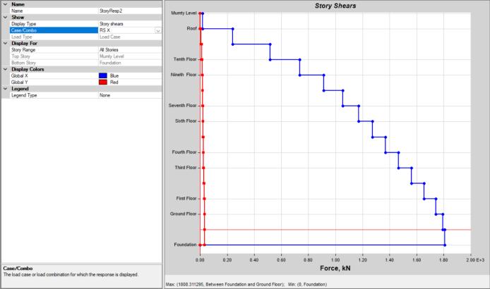
International Research Journal of Engineering and Technology (IRJET) e-ISSN: 2395-0056
Volume: 13 Issue: 03 | Mar 2026 www.irjet.net p-ISSN: 2395-0072
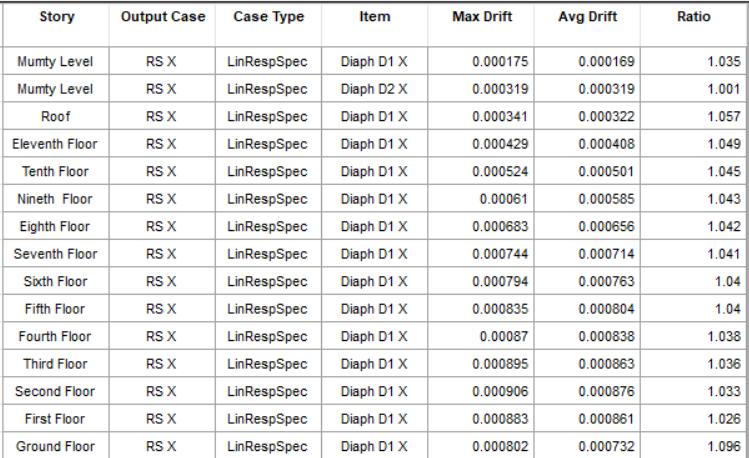
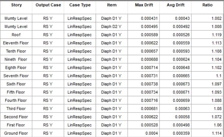
e) Average Drift Ratios:
International Research Journal of
Volume: 13 Issue: 03 | Mar 2026 www.irjet.net
Thestructuralperformance oftheG+12RCCbuildingwas evaluated through a series of stability and serviceability checksinaccordancewithrelevantIndianStandardcodes. Themaximumstoreydriftobtainedfromresponsespectrum analysisinbothXandYdirectionswasfoundtobewithin the permissible limit of 0.004 times the storey height as specified in IS 1893:2016, indicating adequate lateral stiffnessofthestructure.
The torsional irregularity ratio, defined as the ratio of maximumtoaveragestoreydrift,wasobservedtobewithin theacceptablelimitof1.2,confirmingthatthestructuredoes notexhibitsignificanttorsionalirregularity.Thisindicatesa reasonably symmetric distribution of mass and stiffness alongtheplan.
Part1 (Table 6)
Part1 (Table 6)
IS
Part1 (Table 6)
Themaximumlateraldisplacementofthestructureunder windloadingwasfoundtobewithinthepermissiblelimitof H/500 as per IS 456:2000, ensuring satisfactory serviceabilityperformanceunderwindeffects.
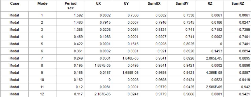
Further,modalanalysisresultsshowedthatthecumulative modal mass participation exceeded 90% in both principal directions,satisfyingtherequirementsofIS1893:2016.The fundamentalmodespredominantlyexhibitedtranslational behaviour in the respective directions, indicating proper dynamiccharacteristicsofthestructure.
Overall,allstabilityandserviceabilitycriteriawere satisfied,confirmingthatthestructureissafe,stable,and performsadequatelyunderbothseismicandwindloading condition
International Research Journal of Engineering and Technology (IRJET) e-ISSN: 2395-0056
Volume: 13 Issue: 03 | Mar 2026 www.irjet.net p-ISSN: 2395-0072
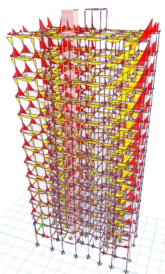
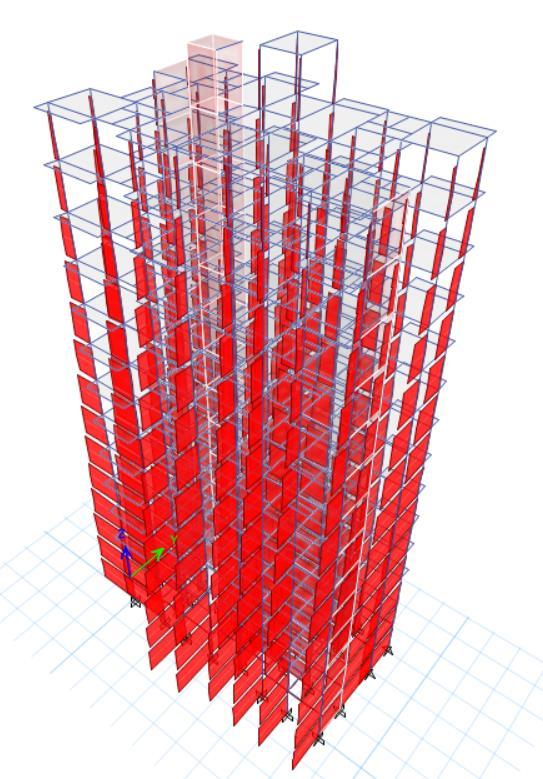
Afterconductingthestabilityandotherimportantchecks, thenextstepistoanalyzethedatarequiredforthedesignof members.
Thethreeimportantdatapointsthatwewillneedare:
a)BendingMomentDiagram.
b)ShearForceDiagram.
c)AxialforceDiagram.
a) Bending Moment Diagram:
b) Shear Force Diagram
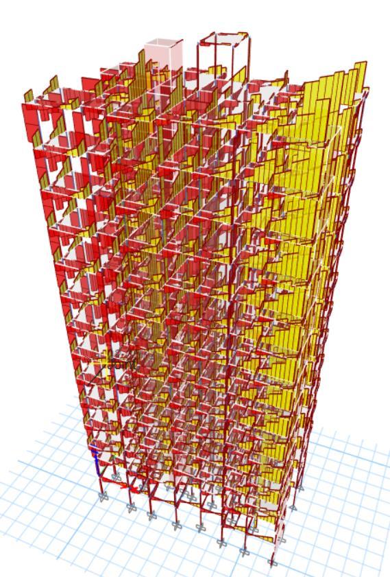
25: ShearForceDiagram
c) Axial Force Diagram
Volume: 13 Issue: 03 | Mar 2026 www.irjet.net
2.9. Designing of Members:
a) Load Combinations used:
Table 11: LoadCombinations
IMPORTANT NOTE: ETABS software is mainly used for analysis purpose. It should be understood that ETABS is not a dedicated design software, and its main role is to generate analysis results like forces, displacements and stability parameters which are required for design. However, ETABS also provides basic design and checking options, which we have used in this project to check member behaviour, identify critical members and get approximate reinforcement requirement. These results are used only for checking and validation purpose. Also, detailing of structural members is done in ETABS itself and no separate detailing software is used. But still, ETABS is mainly considered as an analysis tool in this project.
But for more accurate detailing as per codal provisions, one can use, CSI SAFE for Foundation & Flat Slabs analysis and RCDC for Structural designing and detailing.
b) Designing:
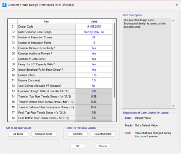
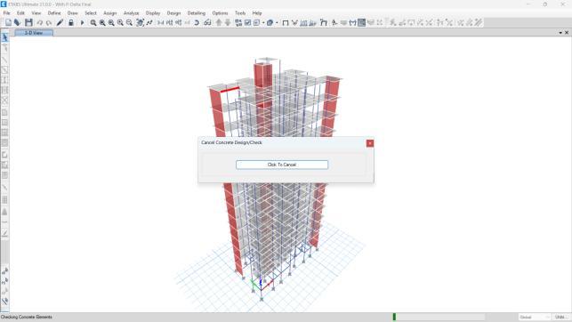
27: DesignPreferences Figure 28: DesigningCheck
International Research Journal of Engineering and Technology (IRJET) e-ISSN: 2395-0056
Volume: 13 Issue: 03 | Mar 2026 www.irjet.net p-ISSN: 2395-0072
Figure 31: DesignCheck
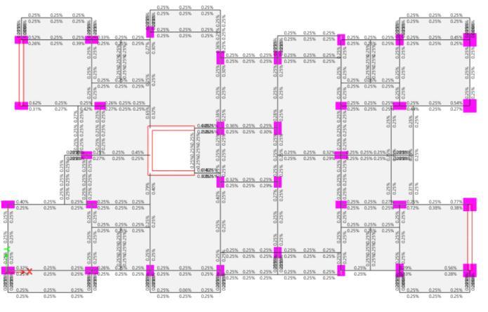
Figure 29: TotalRebarPercentage(Beam)
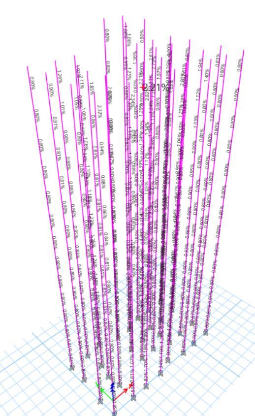
Figure 30: TotalRebarPercentage(Column)
Figures29and30showthereinforcementpercentagetaken from ETABS for beams and columns. The software gives requiredsteelpercentagebasedonanalysisresults,andthis ismainlyusedforcheckingpurpose.Furtherreinforcement detailing is done manually using these values. Also, minimum reinforcement as per IS 456:2000 is checked separatelytomakesurethedesignissafe.
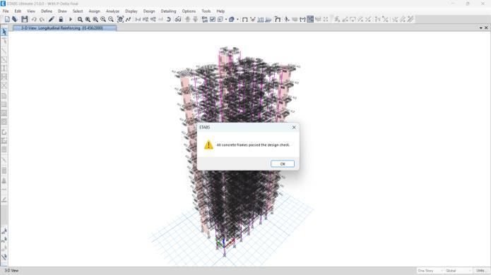
Figure31showsthedesigncheckcarriedoutinETABS.The model was checked for all structural members to verify safetyunderappliedloads.Thesoftwareindicateswhether themembersaresafeornotbasedondesigncriteriaasper IScodes.Anywarningsordesignissueswerereviewedand necessarycorrectionsweremadeinthemodel
2. CONCLUSION:
The G+11 RCC building is analysed and designed using ETABS. The structure is checked for gravity, wind and seismic loads using response spectrum method as per IS codes.Allmembersaredesignedandcheckedforsafety.
Fromresultsitisseenthatdisplacementandstoreydriftis within limit, so structure is safe. Reinforcement given in beamsandcolumnsisokasperdesign.Overallstructureis safeandstableforgivenloading
HENCE THE STRUCUTRE IS SAFE.
5. REFERENCES:
A) Academic Reference:
1)DesignofR.C.C.StructuresbyN.KrishnaRaju.
2) Design of Reinforced Concrete Structures by N. SUBRAMANIAM
3)AnalysisandDesignofMulti-StoreyBuildingUsingEtabs by Mohamed Shajahan , Kumaran, Arivazhagan , Dr. T. Ilango4Volume6,Issue2,March-April2024
4) Seismic Analysis and Design of G+10 Builidng across different environment zones using etab by 1) Depak Watekar,2)VedantGaikwad3)RajLokhande4)Shubham Kadam.
5)AnalysisandDesignofMultistoreyBuildingusingETABS FathimaShalbana1,NibaE1,FarsanaCV1,AthulyaVijayN2
International Research Journal of Engineering and Technology (IRJET) e-ISSN: 2395-0056
Volume: 13 Issue: 03 | Mar 2026 www.irjet.net p-ISSN: 2395-0072
1Students,2Assistant Professor, Department of Civil Engineering, KMCT College of Engineering for Women, Kerala,India
6)DesignExampleofaSixStoreyBuildingbyDr.H.J.Shah DepartmentofAppliedMechanics,M.S.UniversityofBaroda Vadodara,Dr.SudhirKJainDepartmentofCivilEngineering Indian Institute of Technology Kanpur, Kanpur Document No.:IITK-GSDMA-EQ26-V3.0
7) IS 456:2000, Plain and Reinforced Concrete – Code of Practice,BIS,NewDelhi
8)IS1893(Part1):2016, Criteria for Earthquake Resistant Design of Structures,BIS,NewDelhi.
9) IS 13920:2016, Ductile Detailing of Reinforced Concrete Structures,BIS,NewDelhi
10IS875(Part1):1987, Code of Practice for Dead Loads,BIS, NewDelhi.
11)IS875(Part2):1987, Imposed Loads,BIS,NewDelhi
12)IS875(Part3):2015, Wind Loads,BIS,NewDelhi.
International Research Journal of Engineering and Technology (IRJET) e-ISSN: 2395-0056
Volume: 13 Issue: 03 | Mar 2026 www.irjet.net p-ISSN: 2395-0072
BIOGRAPHIES:




Name:TanmayKKulkarni
Branch:B.ECivil
Institute: G.V Acharya Institute of Engineering&Technology,Shelu,Karjat, Maharashtra,INDIA
Name:HardikJoshi
Branch:B.ECivil
Institute: G.V Acharya Institute of Engineering & Technology, Shelu, Karjat, Maharashtra,INDIA
Name:PurveshMeher
Branch:B.ECivil
Institute: G.V Acharya Institute of Engineering&Technology,Shelu,Karjat, Maharashtra,INDIA
Name:JeevanMane
Branch:B.ECivil
Institute: G.V Acharya Institute of Engineering & Technology, Shelu, Karjat, Maharashtra,INDIA