
International Research Journal of Engineering and Technology (IRJET) e-ISSN: 2395-0056
Volume: 13 Issue: 01 | Jan 2026 www.irjet.net p-ISSN: 2395-0072
International Research Journal of Engineering and Technology (IRJET) e-ISSN: 2395-0056
Volume: 13 Issue: 01 | Jan 2026 www.irjet.net p-ISSN: 2395-0072
Sinchana swamy1 , Dr. Kiran T2
1Student of Master in Technology, Department of Civil Engineering, Major: Press tressed concrete Engineering, University of Visveswaraya college of Engineering, Bangalore, Karnataka, India, 2Associate Professor, Department of Civil Engineering, University of Visveswaraya college of Engineering, Bangalore, Karnataka, India,
Abstract - corrosion of traditional steel reinforcement is a major durability issue in RC structures, especially those subjected to severe environments. Application of FibberReinforced Polymer (FRP) systems, which investigate environment-friendlysolutions withenhanceddurabilityand tensile strength while maintaining a favourable strength-toweight ratio, has emerged as a major consideration. The flexuralbehaviourofstandardHYSDsteel-reinforcedconcrete beams and hybrid-metal beams consisting of HYSD steel longitudinal bars along with glass fibre-reinforced polymer (GFRP) stirrups was examined in this experimental investigation. An experimental program was created on four RCbeamspecimenstestedunderfour-pointbending.Ofthese, twobeamswereentirelyreinforcedwithHYSDsteelbarstobe used as control specimens, while the last two beams were reinforced with main bars in HYSD steel and stirrups using GFRP.Thefourbeamsfeaturedcomparatorspecimenshaving the same dimensions, concrete grade, and longitudinal reinforcementtomaintainconsistencyandreliability.Flexural response of specimens was evaluated in terms of loaddeflection behaviour, crack initiation and propagation, stiffnessdegradation,shearcrackdevelopment,ultimateloadcarrying capacity. The results of the experiment showed that with the introduction of GFRP stirrups, cracking pattern in and post-cracking response were changed in RC beams resulting to better crack distribution and durability performance. However, it was observed that overall flexural strength of the beams depended much on the HYSD steel longitudinalreinforcement.Thisstudyprovedthathybriduse ofGFRP-stirrupsmayeffectivelyreplacenormalsteelstirrups in RC flexural members, without compromising the performance of structures.
Keywords: GFRP bars; HYSD bars; Flexural behaviour; Reinforced concrete beams; Four-point bending
1.
Reinforced concrete is the most popular construction material.Ithasstrength,versatility,andcost-effectiveness that are hard to beat. Traditionally, the use of high yield strength deformed (HYSD) steel bars in everything from longitudinal reinforcementtostirrupsisconcerningin RC members. The durability of such structures is affected by steelcorrosionresultingfromaggressiveenvironments,such ascoastalregions,industrialzones,andexposuretode-icing
salts.Corrosioninduces crackingand spallingof concrete, degeneratedbondstrength,andultimatelyresultinginloss ofcarryingcapacityandlifeinstructures.
Fibbershaveemergedasanalternativematerialinreplacing the conventional steel reinforcement. Among the various types of FRPs manufactured, the one that is commonly recognized is that of glass-shredded reinforced polymer bars.TheseGFRPtypeswerechosenfortheirpropertiesof corrosion resistance, very high tensile strength, nonmagneticnature,andlightweight.Althoughtherehasbeen considerable research focusing on the behaviour of RC beamsunderGFRPlongitudinalbars,theinformationonthe structuralbehaviourofsuchbeamswithGFRPusedasthe transversereinforcementislimited.
Stirrups have some important functions concerning shear cracks, confinement, and ductility in RC beams. Replacing themwithGFRPstirrupswillcertainlyincreasedurabilityto agreatextentduetotheabsenceofcorrosionintheshear reinforcementzone.Theelasticandbrittlebehaviourofthe GFRPrequiresanin-depthunderstandingofitsinfluenceon the crack, stiffness, and entire flexural output of the RC beams.
Thus, this investigation aims to conduct an experimental studyontheflexuralbehaviourofconventionalreinforced concrete beams and hybrid reinforcement using conventional HYSD steel bars with GFRP stirrups. The comparativeassessmentmadewillbewithrespecttoloaddeflectionresponse,crackingcharacteristics,stiffness,and ultimate load carrying capacity to understand the applicabilityofGFRPstirrupsinRCflexuralmembers.
2.1
Inthisstudy,OrdinaryPortlandCement(OPC)of53grades was used, and it meets IS 12269:2013. The reason for choosing OPC 53-grade cement was its property of being highinearlystrengthandhencecanbeusedforstructural concreteapplications.Thecementusedwasfresh,freefrom lumps,andstoredindryconditions.Manufacturedsand(Msand) was used as a fine aggregate. The M-sand was maintained clean, well-graded, and free from organic
International Research Journal of Engineering and Technology (IRJET) e-ISSN: 2395-0056
Volume: 13 Issue: 01 | Jan 2026 www.irjet.net p-ISSN: 2395-0072
impurities, clay, and other deleterious materials so as to enhanceparticlepackingandensureaconsistentqualityof the concrete mix. Crushed angular coarse aggregates, nominal maximumsize20 mm, were usedto enhance the interlockingandstrengthcharacteristicsoftheconcrete.
M30-gradeconcretewasdesignedasperIS10262:2019and IS 456:2000 to conform to the required target mean strength,workability,anddurability.Standardconcretecube specimenswerecastandtested,compressivelyat7and28 days,toascertainthecompressivestrengthoftheconcrete. Inallbeamspecimens,HighYieldStrengthDeformed(HYSD) steelbarsofgradeFe500asperIS1786:2008wereusedas thelongitudinalreinforcementwhileMildsteelwasusedas stirrupsinthecontrolbeams.Fe500steelwasselecteddue toitshighyieldstrength,goodductility,andreliablebond characteristicswithconcrete.Theyieldstrengthofthesteel wastakenas500MPa,andthemodulusofelasticityas200 GPa,aspertherecommendationsofIndianStandards.Inthe hybrid beam specimens, Glass Fiber Reinforced Polymer (GFRP)barswereusedasstirrups.TheGFRPbarspossess high tensile strengths, corrosion resistances, and linear elastic behavior up to failure, thereby acting as a suitable alternativetoconventionalsteelstirrups,especiallyinplaces where durability is a major consideration.M30-grade concrete was designed as per IS 10262:2019 and IS 456:2000toconformtotherequiredtargetmeanstrength, workability, and durability. Standard concrete cube specimenswerecastandtested,compressivelyat7and28 days,toascertainthecompressivestrengthoftheconcrete. Inallbeamspecimens,HighYieldStrengthDeformed(HYSD) steelbarsofgradeFe500asperIS1786:2008wereusedas thelongitudinalreinforcementwhileMildsteelwasusedas stirrupsinthecontrolbeams.Fe500steelwasselecteddue toitshighyieldstrength,goodductility,andreliablebond characteristicswithconcrete.Theyieldstrengthofthesteel wastakenas500MPa,andthemodulusofelasticityas200 GPa,aspertherecommendationsofIndianStandards.Inthe hybrid beam specimens, Glass Fiber Reinforced Polymer (GFRP)barswereusedasstirrups.TheGFRPbarspossess high tensile strengths, corrosion resistances, and linear elastic behavior up to failure, thereby acting as a suitable alternativetoconventionalsteelstirrups,especiallyinplaces wheredurabilityisamajorconsideration.
The concrete mix used in the present experimental investigation was designed for M30 grade in accordance withIS10262:2019andIS 456:2000.Themixdesign was done to achieve the desirable target mean compressive strength,adequateworkability,anddurabilityattributesof reinforced concrete beam specimens. Ordinary Portland Cement(OPC)of53gradeswasusedasthebindingmaterial, while manufactured sand (M-sand) was adopted as fine aggregate.Coarseaggregate consistedofartificial crushed angular 20 mm nominal maximum size aggregates. The water-cementratiowascarefullychosentofulfiltheneedsof
strengthanddurabilitywhilstallowingenoughworkability for proper placement and compaction of the concrete in beam moulds. The proportions of cement, fine aggregate, coarseaggregate,andwaterwereadjustedwithtrialmixes to allow for a unified, cohesive mix with minimum segregationandbleeding.Sufficientworkabilitywasgivento allow for proper compaction of concrete around reinforcement,especiallyincloselyspacedstirrupareas. ThemixproportionsadoptedforM30concreteusedinthe studyaresummarizedinTable2.1.
Table 2.1
Theflexuralbehaviourofreinforcedconcretebeamsisthe subject of an experimental program. These beams are conventionallyreinforcedusingHYSDsteelbarsandhybrid reinforcementinvolvinglongitudinalbarsofHYSDsteeland transverse or stirrups made of GFRP. Four reinforced concrete beam specimens were cast for tests to be done underlaboratoryconditions.Controlspecimenswerecreated usingonlyHYSDsteelbarsfortheirdetailedreinforcement, and the rest, two of them, had longitudinal reinforcement made of HYSD steel and GFRP bars as stirrups. All beam specimensweresupposedtodesignwithsimilargeometric dimensions,concretegrade,longitudinalreinforcementratio, and shear span length for a consistent and meaningful comparativeanalysisbetweencontrolandhybridbeams.
The beams were casted in M30 grade concrete and cured under water for 28 days. Proper conditioning was given before testing by preparing the specimens and marking referencepointsforcrackobservationandinstrumentation. Theflexuralanalysiswascarriedoutbyusinga four-point bending setup which defined a constant moment region betweentwoloadingpointsandalsoprovidesclearflexural observation behaviour. The specified span had the beams simply supported, and the load applied monotonically by hydraulicloadingframe.Loadapplicationincreasedgradually and, simultaneously, mid-span deflections were measured througheitherdialgaugesordisplacementtransducers.
Duringtesting,everyspecimenhadfirstvisiblecrackload, crackpatternandpropagation,load–deflectionresponse,and ultimateloadrecorded.Theobservationanddocumentation ofeachbeam'sfailuremodetookplace.Controlledandhybrid beamswereincomparisonforthestudyontheeffectofGFRP
International Research Journal of Engineering and Technology (IRJET) e-ISSN: 2395-0056
Volume: 13 Issue: 01 | Jan 2026 www.irjet.net p-ISSN: 2395-0072
stirrups on flexural performance, stiffness, cracking behaviour,andload-carryingcapacityofreinforcedconcrete beams.
Theexperimentalinvestigationonflexuralbehaviourof RCbeamsreinforcedwithconventionalHYSDsteelbarsand hybrid reinforcement using GFRP stirrups encompassed a total of four reinforced concrete beam specimens. All the beam specimens were cast with identical geometric dimensionsof150x200x1200mmtoeliminatetheinfluence of size effects, thus ensuring a reliable comparison. The beams were designed as simply supported members and detailed to promote flexural failure as opposed to shear failure.Twobeamspecimenswerereinforcedentirelywith HYSDsteelbarsanddesignatedascontrolspecimens,while theremainingtwobeamswerereinforcedwithHYSDsteelas longitudinal reinforcement and GFRP bars as stirrups, representinghybridreinforcement.
Beams
Specimen No
Reinforcement
Specimen-1 HYSD(M)+HYSD(S)
Specimen-2 HYSD(M)+HYSD(S)
Specimen-3 HYSD(M)+GFRP(S)
Specimen-4 HYSD(M)+GFRP(S)
Flexuralbehaviorunderfour-pointbenttestwithallbeam specimens.Allbeamsweresimplysupportedovereffective spans in which two symmetrical equal point loads were applied to the mid-span in order to create a constant bending moment region between the two points. The application of load was ensured through distribution by hydraulic jack through a spreader beam. Load application performedstepbystepcontinueddisplacementcontroltill completefailureofspecimens.ThesameLVDTsaccurately measuredverticaldeflectionatthemid-span.
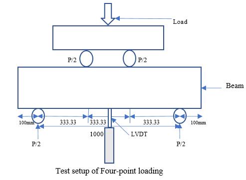
Appropriate instrumentation allowed for accurate measurements of the structural response of the beam specimens during flexural testing. All beams were tested underafour-pointbendingconfigurationusingahydraulic loading frame with sufficient capacity. During testing, the load applied was recorded accurately throughout the experimentbyusingacalibratedloadcellconnectedtothe loading system. The load was applied monotonically in increments until failure of the specimen, and load values wererecordedateachloadingstage.
Mid-spandeflectionofthebeamspecimenswasmeasured usingadialgaugeorLinearVariableDifferentialTransformer (LVDT) placed at the centre of the span. The measuring devicewassecurelyinstalledonanisolatedreferenceframe toavoidanyinfluencefromsupportsettlementsorexternal disturbances.Inadditiontomid-spandeflection,deflection readings were also taken at selected locations close to the loading points when required to study the deformation profile of the beam. Crack development was visually monitored throughout the test, and initiation and propagationofcracksweremarkedonthebeamsurfaceat variousloadlevels.Thewidthandpatternofcracksobserved wereutilizedtoassessthecrackingbehaviourofbothcontrol andhybridbeams.
All measurements were taken at regular load intervals with emphasis on monitoring cracking load and ultimate load.Theinstrumentationsystemprovidedassessmentsof load-deflectionbehaviour,stiffnesscharacteristics,cracking response, and overall flexural performance of beam specimensreinforcedwithsteelandGFRPstirrups.
DeflectionFormula:
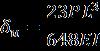
Thefollowinganalysesarecontainedtherein:flexuraltest designofreinforcedconcretebeamspecimens.Thefocusof analysis for these specimens is to study their structural response in four-point bending. Beam behaviour was addressed in terms of load–deflection response, cracking characteristics, variations in stiffness with respect to different stages of loading, and ultimate load-carrying capacity; a special emphasis is given to highlighting the differences in elastic and post-cracking behaviours of the beamspecimens.Thefirstcrackload,crackpropagationwith incrementing loads, and deformation characteristics until thepointoffailureare,therefore,discussedextensivelyto getacompleteviewofthebeam'sflexuralperformance.
International Research Journal of Engineering and Technology (IRJET) e-ISSN: 2395-0056
Volume: 13 Issue: 01 | Jan 2026 www.irjet.net p-ISSN: 2395-0072
Acontrastingevaluationisconductedbetweenthecontrol beamsentirelyreinforcedwithconventionalHYSDsteelbars andthehybridbeamswithHYSDsteellongitudinalbarsand GFRP stirrups. The comparison attempts to evaluate the effectofreplacingsteelstirrupswithGFRPstirrupsonthe flexural response of the reinforced concrete beams. The effectofthestirrupmaterialonstiffnessdegradation,crack propagation,andfailurecharacteristicswillbestudiedwith all beams having identical geometry, the same concrete grade, and longitudinal reinforcement. The comparative studyprovidesaninsightintothefeasibilityandefficiencyof GFRP stirrups as corrosion-resistant substitutes for steel stirrupswithoutcompromisingtheflexuralperformanceof theRCbeam
Table 4.1 ExperimentalVersusTheoreticalFirstcrack laod
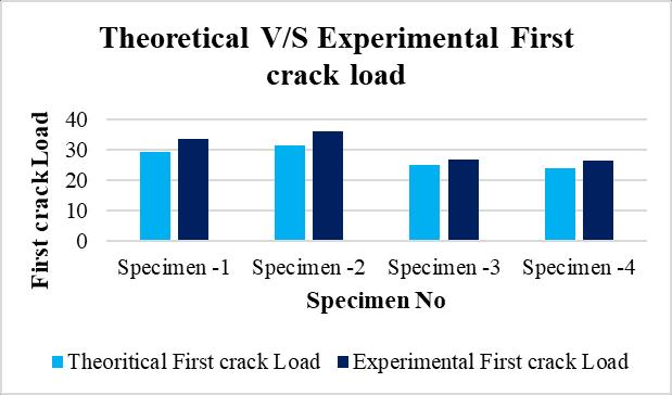
Chart -1:Theoretical
TheTheoreticalandExperimentalcomparisonsoffirstcrack loads have shown that the results of the experiment have alwaysbeenhigherinallbeamspecimens.Theincreaseof Specimen-1from29.2kNto33.51kNandSpecimen-2from 31.34kNto35.82kNconstitutethesamepattern.Likewise, theexperimentalfirstcrackloadsforSpecimen-3and-4were 26.75 kN and 26.45 kN, against 24.84 kN and 23.99 kN, defined as the theoretical values, respectively. Such an increaseisattributedtorandomvariationsinthematerial, high tensile strength of concrete and conservative assumptionsusedintheoreticalcalculations;nevertheless, this justifies a fair correlation between theory and experiment.
Table 4.2 ExperimentalVersusTheoreticalFirstcrack Deflection
Theoretical
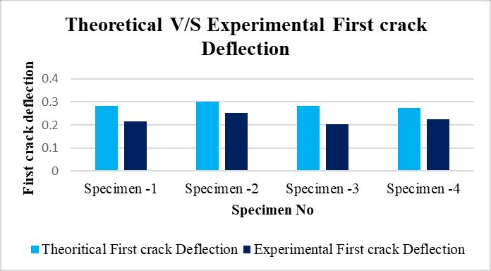
Chart -1:TheoreticalV/SExperimentalFirstcrack Deflection
Thecomparisonbetweentheoreticalandexperimentalfirst crackdeflectionsindicatesthattheexperimentallymeasured deflectionshave,ingeneral,alwaysremainedlessthanthe theoreticalpredictionsforallbeamspecimens.Forinstance, Specimen-1hasdroppedfromatheoreticalvalueof0.282 mm to an experimental one of 0.215 mm. Specimen-2 similarly dropped from 0.303 mm on the theoretical side down to 0.254 mm. Specimens 3 and 4 reported experimental deflections of 0.204 mm and 0.225 mm, respectively,againsttheoreticalpredictionsof0.283mmand 0.273 mm. The lower experimental deflections might be attributedtohigheractual stiffness,material nonlinearity, andconservativeassumptionsimplemented in theoretical calculations.
Table 4.3 ExperimentalVersusTheoreticalUltimateload
International Research Journal of Engineering and Technology (IRJET) e-ISSN: 2395-0056
Volume: 13 Issue: 01 | Jan 2026 www.irjet.net p-ISSN: 2395-0072
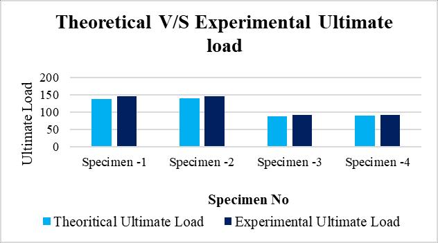
Chart -1:TheoreticalV/SExperimentalUltimateLoad
The comparison of theoretical and experimental comparative ultimate loads indicates that experimental valuesaresomewhatmorethantheoreticalpredictionsfor allbeamspecimens.Specimen1increasedfrom137.36kNto 145.06kN,whereasSpecimen2increasedfrom139.25kNto 146.85 kN. Likewise, Specimens 3 and 4 also showed experimental ultimate loads of 91.25 kN and 92.55 kN against theoretical values of 88.04 kN and 89.51 kN, respectively. The close agreement indicates that the theoretical approach renders conservative yet reliable predictionsofultimateload-carryingcapacity.
Table 4.3 ExperimentalVersusTheoreticalUltimateload Theoretical Experimental
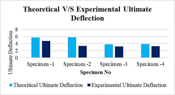
Chart -1:TheoreticalV/SExperimentalUltimateDeflection
Underallbeamcasesinexperiment,ithasbeenseenthatthe actual deflections are lesser than those of the theoretical deflectionsincomparisonwiththeultimatetheoreticaland experimental deflections. For instance, specimen-1 has experimental ultimate deflections of 4.75 mm, with a theoretical value of 5.667 mm, while specimen-2 has a
difference from 5.745 mm to 3.35 mm. Again, specimen-3 andspecimen-4havetheirexperimentalshowingintermsof ultimatedeflectionas3.15mmand3.24mm,respectively, whiletheirtheoreticalvalueswere3.769mmand3.832mm. Hence, these lower experimental deflections probably indicate higher real stiffness while the assumption in theoreticalcalculationofdeflectionswasmoreconservative.
Underfour-pointbending,crackinitiationwasobservedfor alltheaugmentedconcretebeamspecimensintheconstant moment region, thereby indicating a flexure-dominated behavior.Theearliestvisiblecracksformedonthetension facenearmid-spanwhentheappliedmomentcrossedthe tensile strength of concrete. Prior to cracking, all beams exhibited linear elastic behavior with high stiffness, as establishedbytheinitialslopeoftheload–deflectioncurves. Thefirstcrackloadsrecordedexperimentallywere,onthe whole, higher than those theoretically obtained; implying conservativeassumptionswereadoptedintheanalysis.
Withtheinitiationofthefirstcrack,agraduallossofload–deflection stiffness began because of the appearance and spreadingofflexuralcracks.Thecontrolbeamsreinforced withH.Y.S.D.steelshowedcomparativelybettercontrolof thedevelopmentofcracksandlesserreductioninstiffness duetotheductilenatureof steel reinforcement,whilethe beamswithGFRPstirrupsshowedslightlyhigherreduction in stiffness in the post-cracking stage owing to the linearelasticbehaviorofGFRP.Nevertheless,theoverallflexural responsewasdeemedacceptable,indicatingthattheGFRP stirrupswerereliableinthedesignofRCbeams.
The experimental evaluation of ultimate load-bearing capacityforallthereinforcedconcretebeamspecimenswas carriedoutbaseduponthemaximumloadsustainedduring four-point bending tests. All the beams showed a gradual increaseinloadwithincreasingdeflectionandfinallyfailing dueto extensiveflexural crackingfollowed bycrushing of concrete in the compression zone. Experimental ultimate load-carrying capacities were slightly higher than the corresponding theoretical values for all specimens, indicatingthatsuchanalyticalpredictionsareconservative. Control beams fully reinforced with HYSD steel bars exhibited a marginally increased load-carrying capacity owing to the improved confinement and ductile behavior provided by steel stirrups. However, hybrid beams reinforcedwithHYSDlongitudinalbarsandGFRPstirrups attained comparable ultimate capacities, showing that flexural strength is mainly dependent on longitudinal reinforcement.Theresultssubstantiatethefeasibilityofthe use of GFRP stirrups without any appreciable loss in load carryingcapacity.
International Research Journal of Engineering and Technology (IRJET) e-ISSN: 2395-0056
Volume: 13 Issue: 01 | Jan 2026 www.irjet.net p-ISSN: 2395-0072
Experimental first crack loads were higher than theoreticalvaluesforallbeamspecimens,implying conservativeanalyticalassumptions.
Crack initiation occurred in the constant moment region, thus confirming the flexure-controlled behaviorofallbeams.
Post-cracking, fully reinforced HYSD steel beams exhibithigherstiffnessandreduceddeflections.
HybridbeamswithGFRPstirrupsshowedaslightly higher degradation of stiffness than pure beams becauseofthelinearelasticnatureofGFRP.
Theultimateload-carryingcapacityofhybridbeams wascomparabletothatofcontrolbeamsindicating that the longitudinal reinforcement governs the flexuralstrength.
Experimentalultimateloadsweremarginallyhigher thanalltheoreticalpredictions.
The usage of GFRP stirrups effectively controlled crackingandprovidedcorrosionresistance.
ThisstudyconfirmedthatGFRPstirrupscanreplace steel stirrups in the construction of RC beams withoutanoticeabledecrementintheperformance ofthestructure.
[1] IS456:2000,PlainandReinforcedConcrete–Code ofPractice,BureauofIndianStandards,NewDelhi.
[2] IS 10262:2019, Concrete Mix Proportioning –Guidelines,BureauofIndianStandards,NewDelhi.
[3] IS 1786:2008, High Strength Deformed Steel Bars and Wires for Concrete Reinforcement, Bureau of IndianStandards,NewDelhi.
[4] IS 383:2016, Coarse and Fine Aggregate for Concrete – Specification, Bureau of Indian Standards,NewDelhi.
[5] ACI Committee 440 (2015), Guide for the Design andConstructionofStructuralConcreteReinforced with FRP Bars (ACI 440.1R), American Concrete Institute.
[6] Bank, L. C. (2006), Composites for Construction: StructuralDesignwithFRPMaterials,JohnWiley& Sons,NewYork.
[7] Benmokrane, B., El-Salakawy, E., & El-Gamal, S. (2007), “Performance of Concrete Bridge Decks ReinforcedwithFRPBars,” Journal ofComposites forConstruction,ASCE,Vol.11(4),pp.350–360.
[8] Grace,N.F.,Soliman,A.K.,Abdel-Sayed,G.,&Saleh, K.R.(1998),“BehaviorandDuctilityofSimpleand Continuous FRP Reinforced Beams,” Journal of Composites for Construction, ASCE, Vol. 2(4), pp. 186–194.
[9] El-Gamal, S., & Benmokrane, B. (2013), “Shear Strength of FRP-Reinforced Concrete Beams without Transverse Reinforcement,” Journal of CompositesforConstruction,ASCE,Vol.17(3),pp. 368–378.
[10] Toutanji,H.,&Saafi,M.(2000),“FlexuralBehavior of Concrete Beams Reinforced with Glass FiberReinforced Polymer Bars,” ACI Structural Journal, Vol.97(5),pp.712–719.
[11] Rafi,M.M.,Nadjai,A.,Ali,F.,&Talamona,D.(2008), “AspectsofBehaviourofCFRPReinforcedConcrete Beams in Bending,” Construction and Building Materials, Vol.22,pp.277–285.
[12] Bischoff, P. H., & Gross, S. P. (2011), “Equivalent Moment of Inertia for Calculating Deflections of Concrete Members Containing Steel Reinforcement,”ACIStructuralJournal,Vol.108(1), pp.92–100.