
International Research Journal of Engineering and Technology (IRJET) e-ISSN: 2395-0056
Volume: 13 Issue: 03 | Mar 2026 www.irjet.net p-ISSN: 2395-0072
International Research Journal of Engineering and Technology (IRJET) e-ISSN: 2395-0056
Volume: 13 Issue: 03 | Mar 2026 www.irjet.net p-ISSN: 2395-0072
Shweta Maurya1, Dr. Imran Khan2
1Master of Technology, Electrical Engineering, Azad Institute of Engineering and Technology, Lucknow, India
2Professor, Department Electrical Engineering , Azad Institute of Engineering and Technology, Lucknow, India
Abstract -The rapid growth of renewable energy systems and energy storage technologies has significantly increased the demand for efficient power conversion interfaces. In DCcoupled renewable energy systems, bidirectional DC–DC converters play a critical role in enabling controlled power exchangebetweenenergysources,storageunits,andDCbuses. Among various converter configurations, non-isolated bidirectional DC–DC converters have gained considerable attention due to their simple structure, compact size, lower cost, and high efficiency. However, challenges such as switching losses, voltage stress, limited voltage gain, and controlcomplexitystillaffecttheirperformanceinrenewable energy applications. This review paper presents a comprehensive analysis of topology optimization and efficiency enhancement techniques for bidirectional nonisolated DC–DC converters used in DC-coupled renewable systems. The study first discusses the operational principles andfundamentalcharacteristicsofbidirectionalconvertersin renewable energy architectures. Subsequently, various converter topologies reported in the literature including conventional buck–boost, interleaved converters, coupledinductorbasedconverters,switched-capacitorconverters,and multi-port configurations are systematically reviewed and compared. In addition, recent approaches for improving converter efficiency, such as soft-switching techniques, advancedmodulationstrategies,andtheuseofwidebandgap semiconductordevices,arecriticallyexamined.Thepaperalso highlights key design challenges and identifies existing research gaps. Finally, future research directions are presented to guide the development of high-efficiency, compact, and reliable bidirectional converters for nextgeneration renewableenergy systems.
Key Words:Bidirectional DC–DCconverter;Non-isolated converter; Renewable energy systems; DC-coupled microgrid; Topology optimization; Efficiency enhancement.
1.1.1
Theglobaltransitiontowardsustainableenergysystemshas ledtoarapidincreaseintheintegrationofrenewableenergy sourcessuchasphotovoltaic(PV)systems,windturbines, and energy storage technologies into modern electrical power networks. Concerns regarding climate change, depletion of fossil fuels, and environmental sustainability have accelerated the adoption of clean energy solutions worldwide.Asaresult,modernpowersystemsareevolving fromconventionalcentralizedgenerationtowarddistributed and renewable-based architectures. Renewable sources, particularly solar PV and wind energy, are inherently variable and intermittent, which creates challenges in maintaining grid stability and reliable power supply. To address these issues, energy storage systems such as batteriesandsupercapacitorsareincreasinglyincorporated into renewable energy systems to balance generation and loaddemand(Luoetal.,2015).
Inrecentyears,DC-coupledrenewableenergysystemshave gainedsignificantattentionduetotheirimprovedefficiency andsimplifiedpowerconversionstructure.Inthesesystems, renewableenergysourcesandstoragedevicesaredirectly connected to a common DC bus, reducing the number of conversionstagescomparedwithconventionalAC-coupled configurations. This architecture minimizes conversion losses,enhancesoverallsystemefficiency,andallowseasier integrationofdistributedenergyresources.Moreover,DCcoupled systems are particularly suitable for applications suchasphotovoltaicgeneration,batterystorageintegration, electric vehicle charging stations, and DC microgrids. Efficient energy transfer and power regulation in these systems depend heavily on the performance of power electronicconvertersthatmanagevoltagelevelsandcontrol energyflowbetweensystemcomponents(Dragicevicetal., 2016).
Power electronic converters serve as the core interface betweenrenewableenergysources,energystoragedevices, and electrical loads in modern energy systems. These convertersregulatevoltagelevels,controlpowerflow,and ensurestableoperationundervaryinggenerationandload
International Research Journal of Engineering and Technology (IRJET) e-ISSN: 2395-0056
Volume: 13 Issue: 03 | Mar 2026 www.irjet.net p-ISSN: 2395-0072
conditions. In DC-coupled renewable systems, DC–DC convertersarecommonlyemployedtoadaptvoltagelevels and enable bidirectional energy transfer between storage devices and the DC bus. Their performance directly influences system efficiency, reliability, and dynamic response. As renewable energy penetration increases, the demandforhigh-efficiencyandflexibleconvertertopologies has become increasingly important for achieving optimal systemperformance(EricksonandMaksimovic,2001).
1.2.1
BidirectionalDC–DCconvertersplayafundamentalrolein enabling controlled energy exchange between energy storage devices and DC distribution networks. These convertersallowpowertoflowintwodirections,enabling batteriesorsupercapacitorstobothstoreexcessenergyand supply power when renewable generation is insufficient. Duringperiodsofhighrenewablegeneration,theconverter operates in buck mode to charge the storage device by reducing the DC bus voltage to a suitable charging level. Conversely, during periods of low generation or high demand,theconverteroperatesinboostmodetodischarge stored energy back to the DC bus. This bidirectional capability ensures efficient utilization of renewable resources while maintaining energy balance within the system(Zhangetal.,2014).
1.2.2
MaintainingastableDC-linkvoltageiscriticalforthereliable operation of DC-coupled renewable energy systems. Bidirectional converters contribute to this objective by dynamicallyadjustingpowerflowbetweenstoragedevices and the DC bus. When sudden fluctuations occur in renewablegenerationorloaddemand,theconverterrapidly respondsbyeitherabsorbingorsupplyingpower,thereby stabilizing the DC-link voltage. This capability enhances systemresilienceandpreventsvoltageinstabilitythatcould otherwiseaffectconnectedloadsordownstreamconverters. Effective control strategies for bidirectional converters thereforeplayanessentialroleinensuringstableoperation ofrenewable-basedpowersystems(Tanetal.,2015).
BidirectionalDC–DCconvertersarewidelyusedinseveral emergingenergyapplications.Inphotovoltaic-batteryhybrid systems,theseconvertersmanageenergyflowbetweenPV arrays, battery storage, and DC loads. Similarly, in DC microgrids they enable energy sharing among distributed sourcesandstorageunitswhilemaintainingsystemstability. Another major application is in electric vehicles, where
bidirectionalconvertersfacilitateenergytransferbetween vehiclebatteriesandonboardpowersystems.Invehicle-togrid (V2G) systems, these converters even allow electric vehiclestoreturnstoredenergytothegridwhenrequired. Due to their flexibility and high efficiency, bidirectional converters have become a key enabling technology for modern renewable energy infrastructures (Khaligh and Onar,2017).
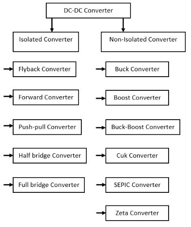
Non-isolated DC–DC converters are widely adopted in renewableenergysystemsbecauseoftheirrelativelysimple structure and high efficiency. Unlike isolated converters, they do not require a high-frequency transformer for galvanic isolation, which significantly reduces circuit complexityandcomponentcount.Theabsenceofmagnetic isolation components also leads to lower conduction and core losses, resulting in improved power conversion efficiency. Furthermore, the simpler architecture allows easiercontrolimplementationandreducesoverallsystem cost,makingnon-isolatedconvertersparticularlyattractive for many practical applications (Mohan, Undeland and Robbins,2003).
Anotherimportantadvantageofnon-isolatedconvertersis theircompactsizeandhighpowerdensity.Sincetheyavoid bulkytransformercomponents,theseconvertersoccupyless physical space and require fewer passive elements. This
International Research Journal of Engineering and Technology (IRJET) e-ISSN: 2395-0056
Volume: 13 Issue: 03 | Mar 2026 www.irjet.net p-ISSN: 2395-0072
featureisparticularlybeneficialinapplicationswherespace andweightarecriticaldesignconsiderations,suchaselectric vehicles, portable energy systems, and distributed renewableinstallations.Additionally,thereducednumberof components lowers manufacturing costs and simplifies system integration. As a result, non-isolated bidirectional converters are widely used in low- and medium-power renewable energy applications where isolation is not mandatory(Hart,2011).
1.3.3 Suitability for Renewable Energy Integration
Due to their high efficiency, compact design, and costeffectiveness,non-isolatedbidirectionalconvertersarewell suitedforrenewableenergyintegration.Theseconverters enable efficient energy exchange between renewable generation sources and energy storage systems while maintaining stable system operation. They are commonly employedinPV-batteryhybridsystems,DCmicrogrids,and electric vehicle energy management systems. However, challengessuchasvoltagegainlimitations,switchinglosses, and component stress still remain in conventional topologies. Consequently, ongoing research focuses on optimizingconvertertopologiesandimprovingefficiencyto meettheperformancerequirementsofmodernrenewable energysystems(Emadi,KhalighandRivetta,2006).
2. ARCHITECTURE OF DC-COUPLED RENEWABLE ENERGY SYSTEMS
2.1 Structure
2.1.1
DC-coupled renewable energy systems are designed to integratemultipleenergysourcesandstorageunitsthrough a commonDCdistributionnetwork.Insucharchitectures, renewablegenerationunitssuchasphotovoltaic(PV)arrays andwindenergysystemsareconnectedtoacentralDCbus throughdedicatedDC–DCconvertersthatregulatevoltage levelsandensureefficientpowertransfer.TheDCbusactsas an intermediate platform where generated power, stored energy, and load demand are coordinated. An inverter is typicallyconnectedtotheDCbustosupplyACloadsorto interfacewiththeutilitygrid.Comparedwithconventional AC-coupledsystems,DC-coupledconfigurationsreducethe number of conversion stages because many renewable sources inherently produce DC power. This reduction minimizesconversionlossesandimprovesoverall system efficiencywhilesimplifyingsystemcontrolandintegration (Guerreroetal.,2013).
In DC-coupled systems, photovoltaic arrays are usually connected through DC–DC converters that perform maximum power point tracking (MPPT) to extract the maximumavailablesolarenergyundervaryingirradiance conditions. The energy produced by PV modules is then suppliedtotheDCbus,whereitcanbeusedtopowerloads, charge energy storage devices, or be exported to the grid throughaninverterinterface.Energystoragesystemssuch as batteries are integrated with the DC bus using bidirectionalDC–DCconvertersthatregulatechargingand discharging processes. This configuration allows flexible power management and ensures that excess renewable energycanbestoredforlateruse.Consequently,DC-coupled architecturesareincreasinglyusedinapplicationssuchas microgrids, renewable charging stations, and distributed powersystemsduetotheirhighefficiencyandadaptability (Justoetal.,2013).
Efficient power conversion plays a crucial role in the performance of DC-coupled renewable systems. Since renewable sources often operate under fluctuating environmentalconditions,powerconvertersmustefficiently regulate voltage levels and manage energy flow between different system components. High-efficiency converters reduce energy losses, improve system reliability, and increase the overall utilization of renewable resources. Additionally, advanced converter control strategies help maintain DC bus voltage stability while accommodating dynamic load and generation conditions. Therefore, the design and optimization of power electronic converters remain a key aspect in improving the performance and scalability of DC-coupled renewable energy architectures (Liserre,SauterandHung,2010).
2.2RoleofEnergyStorageSystemsinDCNetworks
2.2.1
Energy storage systems are essential components in renewableenergynetworksbecausetheyhelpmitigatethe intermittencyassociatedwithrenewablegeneration.Battery energystoragesystemsarecommonlyintegratedintoDCcoupledarchitecturestostoreexcessenergyduringperiods of high renewable generation and supply power during periods of low generation or high demand. Lithium-ion batteries, in particular, are widely used due to their high energydensity,longcyclelife,andrelativelyhighefficiency. In DC networks, batteries are connected through bidirectional DC–DC converters that regulate charging currents and ensure safe operation under varying load conditions.Thisintegrationimprovessystemreliabilityand
International Research Journal of Engineering and Technology (IRJET) e-ISSN: 2395-0056
Volume: 13 Issue: 03 | Mar 2026 www.irjet.net p-ISSN: 2395-0072
allows more effective utilization of renewable energy resources(DivyaandØstergaard,2009).
In addition to batteries, supercapacitors are increasingly usedinrenewableenergysystemstoproviderapidenergy buffering and improve dynamic performance. Supercapacitors possess high power density and can respondquicklytosuddenpowerfluctuations,makingthem suitableforapplicationsthatrequirefasttransientresponse. When integrated into DC networks, supercapacitors can absorb short-term power surges and stabilize voltage variations caused by sudden load changes or renewable generation fluctuations. They are often used in hybrid energy storage systems together with batteries, where batteries provide long-term energy storage while supercapacitorshandlehigh-powertransientevents(Burke, 2000).
2.2.3
The integration of energy storage devices within DC networksrequiresefficientbidirectionalpowerconverters toregulateenergyexchangebetweenstorageunitsandthe DC bus. These converters enable controlled charging and discharging processes while maintaining stable system voltagelevels.Duringchargingoperation,excessrenewable energyisdirectedtowardstoragedevices,whereasduring dischargingoperationstoredenergyissuppliedbacktothe DC network to support loads. Proper control of these converters ensures optimal utilization of storage capacity and enhances the flexibility of renewable energy systems. Consequently, bidirectional DC–DC converters are consideredessentialcomponentsinmodernDCmicrogrid architectures(BidramandDavoudi,2012).
2.3.1
In DC-coupled renewable systems, charging mode occurs whenexcessenergyfromrenewablesourcesisavailableand needs to be stored in energy storage devices. During this mode,thebidirectionalDC–DCconverteroperatesinbuck configurationtostepdowntheDCbusvoltagetoasuitable levelrequiredforbatterycharging.Theconverterregulates the charging current to ensure safe and efficient energy storage while preventing battery overcharging. Proper controlstrategiesarenecessarytomaintainstablecharging conditionsandtooptimizebatterylife.Chargingoperation typicallyoccursduringperiodsofhighsolarirradiationor low load demand when surplus renewable energy is available(Chenetal.,2012).
Dischargingmodetakesplacewhenrenewablegenerationis insufficienttomeetloaddemandorwhenadditionalpower isrequiredtostabilizetheDCbusvoltage.Inthissituation, the bidirectional converter operates in boost mode, increasingthestoragedevicevoltageto matchtheDCbus voltagelevel.Storedenergyfrombatteriesorotherstorage devicesisthereforetransferredtotheDCnetworktosupply loads or support system stability. The boost operation ensurescontinuouspoweravailabilityandenhancessystem reliability during fluctuations in renewable generation (Kjaer,PedersenandBlaabjerg,2005).
Thecombinationofcharginganddischargingmodesallows DC-coupledrenewablesystemstoachievedynamicenergy management. By continuously monitoring generation conditions, load demand, and storage levels, the control systemdeterminestheappropriateoperatingmodeofthe bidirectional converter. This dynamic control strategy enablesoptimalutilizationofrenewableresources,reduces powerfluctuations,andimprovesthestabilityoftheDCbus. As renewable penetration increases, effective power flow controlbecomesincreasinglyimportantforensuringreliable andefficientoperationofDC-basedpowersystems(Lasseter andPaigi,2004).
Bidirectional DC–DC converters are power electronic interfaces that enable energy transfer in two directions between two DC sources or between a DC source and an energystoragesystem.Unlikeconventionalunidirectional converters,whichallowpowerflowonlyfromtheinputto theoutput,bidirectionalconvertersaredesignedtosupport bothcharginganddischargingoperations.Thiscapabilityis essentialinapplicationswhereenergystoragedevicessuch asbatteriesorsupercapacitorsmustbothabsorbandsupply energy dependingonsystemconditions. The fundamental concept of bidirectional operation is based on controlling semiconductorswitchesso that theconvertercan reverse the direction of current flow while maintaining regulated voltagelevels.Asaresult,theseconvertersarewidelyused in renewable energy systems, electric vehicles, and DC microgridswhereflexibleenergymanagementisrequired (Kazimierczuk,2016).
International Research Journal of Engineering and Technology (IRJET) e-ISSN: 2395-0056
Volume: 13 Issue: 03 | Mar 2026 www.irjet.net p-ISSN: 2395-0072
The operation of bidirectional converters relies on highfrequency switching of semiconductor devices such as MOSFETs or IGBTs to regulate voltage and current. By appropriatelycontrollingthedutycycleofswitchingsignals, the converter can operate either in step-down or step-up mode depending on the direction of power flow. During switchingoperation,energyistemporarilystoredinpassive componentssuchasinductorsandcapacitorsbeforebeing transferredtotheoutputside.Advancedcontroltechniques are often implemented to ensure stable operation under varying load conditions and input voltage fluctuations. Effectiveswitchingcontrolnotonlydeterminesthedirection of power flow but also influences converter efficiency, switching losses, and dynamic response characteristics (Rashid,2014).
Bidirectional converters are particularly important in renewable energy systems where energy storage devices must interact dynamically with generation sources and loads. For example, when renewable generation exceeds demand,theconverterenablesenergystoragebydirecting powertowardbatteriesorotherstoragedevices.Conversely, when generation is insufficient, the stored energy can be suppliedbacktothesystem.Thisflexibleenergyexchange improves system stability, increases renewable energy utilization, and enhances overall power management. Consequently, bidirectional converters are considered fundamental components in modern DC-based energy infrastructures(Blaabjerg,YangandYang,2017).
3.2 Basic Bidirectional Buck–Boost Converter
3.2.1 Structure of the Conventional Buck–Boost Converter
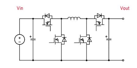
The bidirectional buck–boost converter represents one of themostcommonlyusednon-isolatedconvertertopologies duetoitssimplestructureandflexibleoperation.Thebasic configuration typically consists of two active switches, an inductor, and filtering capacitors that facilitate energy transfer between two DC sources. In this topology, both switchesarecontrolledinsuchawaythattheconvertercan operateeitherasabuckconverterorasaboostconverter dependingonthedirectionofpowerflow.Thesimplicityof this structure results in reduced component count, lower cost,andrelativelystraightforwardcontrolimplementation, making it suitable for a wide range of low- and mediumpowerapplications(Mohan,UndelandandRobbins,2003).
3.2.2
When the converter operates in buck mode, power flows fromthehigher-voltageDCbustothelower-voltageenergy storagedevice.Inthismode,theconverterreducestheinput
voltagebycontrollingthedutycycleoftheswitchingdevice. Energy is stored temporarily in the inductor during the switch-onintervalandthentransferredtotheoutputduring the switch-off interval. This operating mode is commonly usedwhenchargingbatteriesorotherstoragesystemsfrom a higher voltage DC bus, such as in photovoltaic energy storageapplications(EricksonandMaksimovic,2001).
Inboostmode,thedirectionofpowerflowisreversedand energyistransferredfromthelower-voltagestoragedevice to the higher-voltage DC bus. During this operation, the inductor stores energy when the switch is turned on and releases it to the DC bus when the switch is turned off, thereby increasing the output voltage level. This mode is typically used when stored energy is required to support systemloadsormaintainDCbusvoltagestability.Despiteits advantages, the conventional bidirectional buck–boost convertermayexperiencelimitationssuchashighswitching stress,increasedconduction losses,and restrictedvoltage gainwhenoperatingunderhighpowerconditions(Zhanget al.,2014).
3.3.1
Thevoltageconversion ratioisoneofthe mostimportant parameters used to evaluate the performance of DC–DC converters. It represents the relationship between the output voltage and input voltage of the converter and determinesthecapabilityoftheconvertertoadaptvoltage levelswithinthesystem.Ahighervoltageconversionratio allowstheconvertertosupportawiderrangeofoperating conditions, which is particularly important in renewable energy applications where source voltages may vary significantlyduetoenvironmentalconditions(Hart,2011).
Efficiency is a critical factor in power converter design because it determines how effectively electrical energy is transferred from the input to the output. Converter efficiencyisaffectedbyvariouslossmechanismsincluding conductionlossesinsemiconductordevices,switchinglosses during transistor transitions, and losses in passive components such as inductors and capacitors. Highefficiency converters are essential in renewable energy systemsbecausetheyminimizeenergywastageandimprove overallsystemperformance(Krein,1998).
Switching losses occur when semiconductor devices transitionbetweenonandoffstatesduringhigh-frequency operation.Theselossesincreasewithswitchingfrequency andcansignificantlyaffectconverterefficiencyandthermal performance.Powerdensity,definedastheamountofpower
International Research Journal of Engineering and Technology (IRJET) e-ISSN: 2395-0056
Volume: 13 Issue: 03 | Mar 2026 www.irjet.net p-ISSN: 2395-0072
delivered per unit volume, is another important performance metric. Increasing power density requires compact design and efficient thermal management, which are key considerations in modern power electronic converterdevelopment(Luoetal.,2015).
3.3.4
Voltagestressreferstothemaximumvoltageexperiencedby semiconductor devices during converter operation. Excessive voltage stress can reduce device reliability and increasetheriskofcomponentfailure.Therefore,converter topologiesareoftendesignedtominimizevoltagestresson switches and passive components. Dynamic response is anotherimportantparameterthatdescribeshowquicklythe converter can respond to changes in load or input conditions.Afastdynamicresponseisparticularlyimportant in renewable energy systems where generation and load levels may fluctuate rapidly (Emadi, Khaligh and Rivetta, 2006).
The development of bidirectional non-isolated DC–DC convertershasreceivedsignificantattentioninrecentyears duetothegrowingdemandforefficientenergyconversion in renewable energy systems, electric vehicles, and DC microgrids.Researchershaveproposednumerousconverter topologiestoimprovevoltagegain,reduceswitchinglosses, andenhanceoverallsystemefficiency.Thissectionreviews themostwidelystudiedconverterstructuresreportedinthe literature, including conventional topologies, interleaved converters,coupled-inductorconverters,switched-capacitor converters, multi-port converters, and soft-switching configurations.
4.1.1
Thebidirectionalbuck–boostconverterisoneofthemost widely used non-isolated converter topologies for energy storage applications. This converter allows bidirectional power transfer between two DC sources and can operate either in buck mode or boost mode depending on the directionofpowerflow.Thetopologygenerallyconsistsof twoactiveswitches,aninductor,andcapacitorsforenergy storage and filtering. In buck mode, the converter steps down the input voltage to charge the battery or storage device,whileinboostmodeitincreasesthestoragevoltage tosupporttheDCbus.Duetoitssimplestructureandeaseof control,thebidirectionalbuck–boostconverteriscommonly used in renewable energy systems and electric vehicle applications. However, it suffers from several limitations including limited voltage gain, high switching stress on
semiconductordevices,andincreasedconductionlossesat higherpowerlevels(EricksonandMaksimovic,2001).
4.1.2
TheCukconverterisanotherconventionaltopologyusedfor bidirectional power conversion. Unlike the buck–boost converter,theCukconverteremploystwoinductorsanda coupling capacitor to transfer energy between input and outputstages.Thisstructureprovidescontinuouscurrentat both input and output sides, which significantly reduces current ripple and improves power quality. The Cuk converter also exhibits improved electromagnetic interferenceperformancecomparedwithsimplerconverter structures. Nevertheless, the topology requires additional passivecomponentsandresultsinhighercircuitcomplexity andincreasedcost.Furthermore,thepresenceofmultiple inductorsincreasesthephysicalsizeoftheconverter,which may reduce its suitability for compact power electronic systems(MiddlebrookandCuk,1976).
The Single-Ended Primary Inductor Converter (SEPIC) is another non-isolated topology capable of providing bidirectional energy transfer with flexible voltage conversion capability. The SEPIC converter utilizes two inductorsandaseriescouplingcapacitortoregulatevoltage levelswhilemaintainingnon-invertedoutputpolarity.One keyadvantageofthistopologyisitsabilitytooperateacross awideinputvoltagerangewhilemaintainingstableoutput voltage. As a result, SEPIC converters are particularly suitable for renewable energy applications where input voltagesvarysignificantlyduetoenvironmentalconditions. However, the topology requires multiple passive componentsandexperienceshigherconductionlossesdue toadditionalcurrentpaths,whichmaylimititsefficiencyin high-power applications (Mohan, Undeland and Robbins, 2003).
International Research Journal of Engineering and Technology (IRJET) e-ISSN: 2395-0056
Volume: 13 Issue: 03 | Mar 2026 www.irjet.net p-ISSN: 2395-0072
4.2.1 Principle of Interleaving Technique
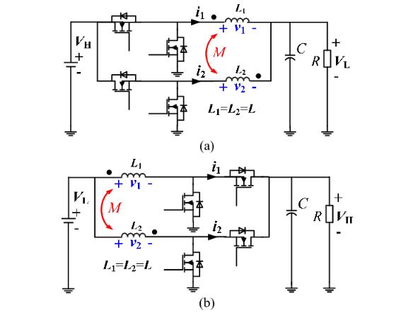
Interleavedbidirectionalconvertershavebeenproposedto improve the performance of conventional converter topologies by distributing the power flow across multiple parallel converter phases. In this approach, several converter modules operate simultaneously with phaseshifted switching signals. The interleaving technique significantly reduces input and output current ripple because the ripple components generated by each phase partiallycanceleachother.Thisreductionincurrentripple allowstheuseofsmallerpassivecomponentsandimproves overall system efficiency. Additionally, current sharing amongmultiplephasesreducesthermalstressonindividual components, enhancing converter reliability and power handlingcapability(Krein,1998).
4.2.2PerformanceAdvantagesofInterleavedConverters
Interleavedconverterstructuresareparticularlybeneficial inhigh-powerrenewableenergysystemsandelectricvehicle powertrains.Bydistributingcurrentacrossmultiplephases, interleaved converters reduce conduction losses and improvedynamicperformanceduringtransientconditions. Furthermore,themodularnatureofinterleavedconverters provides flexibility in system design and scalability for higherpowerlevels.Despitetheseadvantages,theincreased number of switching devices and control complexity may increase system cost and design difficulty (Zhang et al., 2014).
4.3.1 Concept of Coupled Inductors inDC–DCConverters
Coupled-inductor based converters have been widely investigated as an effective method for achieving higher
voltageconversionratioswithoutsignificantlyincreasingthe duty cycle of the switching devices. In these converters, magnetic coupling between inductors allows energy to be transferred more efficiently between input and output stages.Theuseofcoupledinductorsalsoenablesimproved voltage gain and better energy utilization compared with traditional single-inductor topologies. Additionally, the leakage inductance of coupled inductors can be used to reduce switching stress and improve converter efficiency (Blaabjerg,YangandYang,2017).
Converters employing coupled inductors offer several advantages including high voltage gain, reduced switch stress,andimprovedefficiencyinhighstep-uporstep-down applications.Thesecharacteristicsmakethemattractivefor renewableenergysystemswherewidevoltageconversion ranges are required. However, the design of coupled inductors requires careful consideration of magnetic couplingcoefficients,leakageinductance,andcorematerial characteristics. Improper design may lead to increased electromagnetic interference or efficiency losses (Kazimierczuk,2016).
4.4.1
Switched-capacitor converters utilize capacitors as the primary energy transfer elements instead of inductors. In these converters, capacitors are periodically charged and discharged through controlled switching sequences to achieve voltage conversion. The absence of magnetic components makes switched-capacitor converters lightweightandcompact,whichisbeneficialforapplications requiring high power density. These converters can also achieve high voltage conversion ratios without requiring largedutycycles(Fangetal.,2017).
Voltagemultipliercircuitsextendtheconceptofswitchedcapacitorconvertersbyconnectingmultiplecapacitorsand diodesincascadedarrangementstoincreaseoutputvoltage levels. Such configurations are commonly used to achieve highstep-upvoltagegaininrenewableenergysystemswith low-voltage sources such as photovoltaic panels. By increasing the voltage through capacitor multiplication stages, these converters can operate efficiently without placing excessive stress on switching devices. However, capacitorvoltagebalancingandincreasedconductionlosses maypresentdesignchallenges(Hart,2011).
International Research Journal of Engineering and Technology (IRJET) e-ISSN: 2395-0056
Volume: 13 Issue: 03 | Mar 2026 www.irjet.net p-ISSN: 2395-0072
4.5.1
Multi-portDC–DCconvertershaveemergedasaneffective solution for integrating multiple energy sources within a single converter structure. In renewable energy systems, these converters allow simultaneous connection of photovoltaic arrays, batteries, and supercapacitors to a common DC bus. Thisarchitecture reducesthe number of required converters and simplifies system control by enablingcoordinatedenergymanagementwithinaunified topology(KhalighandOnar,2017).
Multi-inputconvertersareparticularlysuitableforhybrid renewablesystemswheredifferentenergysourcesoperate under varying conditions. For example, photovoltaic generationmayfluctuateduetochangesinsolarirradiance, whilebatterystorageprovidesstableenergysupply.Multiportconvertersenableefficientcoordinationbetweenthese sourcesbydynamicallycontrollingpowerflowaccordingto systemdemandandresourceavailability.
Switchinglossesareoneoftheprimarysourcesofefficiency degradation in high-frequency DC–DC converters. Conventional hard-switching converters experience significant energy loss during the transition of semiconductor devices between the on and off states. To address this limitation, advanced switching techniques knownassoft-switchingmethodshavebeendeveloped.Softswitching techniques reduce switching losses by ensuring thateitherthevoltageorcurrentacrosstheswitchingdevice becomes zero before the switching transition occurs. This reducesenergydissipationandimprovesoverallconverter efficiency.Commonsoft-switchingmethodsincluderesonant switching, quasi-resonant converters, and active clamp circuits, which are widely applied in high-performance power electronic converters (Erickson and Maksimovic, 2001).
Twowidelyusedsoft-switchingapproachesarezero-voltage switching (ZVS) and zero-current switching (ZCS). In ZVS operation,theswitchingdeviceturnsonwhenthevoltage acrossitisnearlyzero,therebyminimizingswitchinglosses andreducingelectromagneticinterference.ZCS,ontheother hand,ensuresthatthecurrentthroughtheswitchingdevice becomeszerobeforetheswitchingtransitionoccurs,which significantlyreducesswitchingstressandpowerloss.These techniques are particularly beneficial in bidirectional convertersoperatingathighswitchingfrequencies,asthey improve efficiency while also enhancing device reliability andthermalperformance(Kazimierczuk,2016).
In addition to improving efficiency, soft-switching techniquesalsocontributetoimprovedreliabilityofpower electronicsystems.Byreducingvoltageandcurrentstress on semiconductor devices, soft-switching converters experience lower thermal stress and reduced switchingrelateddegradation.Thisimprovementindevicereliability is particularly important in renewable energy systems, whereconvertersareexpectedtooperatecontinuouslyfor long periods under varying environmental conditions. Consequently, many modern converter topologies incorporatesoft-switchingmechanismstoachievebothhigh efficiencyandlong-termoperationalstability(Rashid,2014).
5.2.1
Traditional silicon-based semiconductor devices such as MOSFETs and IGBTs have been widely used in power electronic converters for several decades. Although these devices provide reliable performance, they suffer from limitations related to switching speed, conduction losses, and thermal performance when operating at high frequencies and high power levels. As renewable energy systems demand higher efficiency and power density, the limitations of conventional silicon devices become more evident, motivating the development of advanced semiconductortechnologies(Mohan,UndelandandRobbins, 2003).
Silicon carbide (SiC) devices have emerged as one of the mostpromisingwidebandgapsemiconductortechnologies for high-efficiency power conversion. SiC devices exhibit superiorelectricalcharacteristicssuchashigherbreakdown voltage, lower switching losses, and better thermal conductivity compared with conventional silicon devices. These properties enable converters to operate at higher switchingfrequencieswhilemaintaininglowerpowerlosses. Asaresult,theuseofSiCMOSFETsinbidirectionalDC–DC converterssignificantlyimprovesefficiencyandreducesthe sizeofpassivecomponentssuchasinductorsandcapacitors (Blaabjerg,YangandYang,2017).
Gallium nitride (GaN) is another wide bandgap semiconductormaterialthatoffersexcellentperformancein high-frequencypowerelectronicsapplications.GaNdevices have extremely fast switching capabilities and low gate charge, which allows converters to operate at very high switchingfrequencieswithminimal switchinglosses.This characteristicleadstohigherpowerdensityandimproved converter efficiency. Due to these advantages, GaN-based converters are increasingly used in renewable energy
International Research Journal of Engineering and Technology (IRJET) e-ISSN: 2395-0056
Volume: 13 Issue: 03 | Mar 2026 www.irjet.net p-ISSN: 2395-0072
systems,electricvehicles,andhigh-performanceDCpower distributionnetworks(Millánetal.,2014).
5.3.1
Control strategies play a crucial role in determining the performance,efficiency,andstabilityofbidirectionalDC–DC converters.Inrenewableenergysystems,convertersmust operate under varying input voltages, fluctuating load conditions, and dynamic environmental factors. Conventionalcontrolmethodssuchasproportional–integral (PI)controlmaynotprovidesufficientperformanceunder such conditions. Therefore, advanced modulation and controltechniqueshavebeendevelopedtoimprovedynamic response, reduce steady-state errors, and enhance overall systemefficiency(Krein,1998).
5.3.2
ModelPredictiveControlhasgainedsignificantattentionin recent years due to its ability to handle nonlinear system dynamics and multiple control objectives simultaneously. MPCpredictsfuturesystembehaviorusingamathematical modeloftheconverterandselectsoptimalcontrolactions that minimize a predefined cost function. This predictive capability allows the converter to respond quickly to disturbances and maintain stable operation under rapidly changing conditions. Consequently, MPC is increasingly appliedinrenewableenergysystemsandDCmicrogridsfor efficientpowermanagement(CamachoandBordons,2007).
SlidingModeControlisarobustnonlinearcontrolmethod widelyusedinpowerelectronicconvertersduetoitsstrong disturbancerejectioncapabilityandfastdynamicresponse. InSMC,thesystemstatesareforcedtofollowapredefined sliding surface, ensuring stable operation even under parameter variations and external disturbances. This property makessliding modecontrol particularlysuitable forrenewableenergysystemswhereoperatingconditions frequently change. Additionally, SMC offers improved robustness compared with conventional linear control techniques(Utkin,GuldnerandShi,2009).
Artificialintelligenceandmachinelearningtechniquesare increasinglybeingexploredforadvancedcontrolofpower electronicconverters.AI-basedcontrollers,includingneural networks,fuzzylogicsystems,andreinforcementlearning algorithms,canadapttocomplexsystemdynamicsandlearn optimalcontrolstrategiesthroughtrainingorreal-timedata analysis. These intelligent control approaches enable improved efficiency, better fault tolerance, and enhanced adaptabilityinrenewableenergysystems.Ascomputational
capabilitiescontinuetoimprove,AI-basedcontrolmethods areexpectedtoplayanincreasinglyimportantroleinnextgenerationpowerelectronicconvertersystems(Dragicevic etal.,2019).
The performance of bidirectional non-isolated DC–DC converters depends strongly on their topology, switching strategy, and component configuration. Over the past decade,numerousconverterstructureshavebeenproposed to improve efficiency, voltage gain capability, and power densityfor renewable energyapplications.However, each topologypresentsdifferenttrade-offsintermsofcomplexity, cost, and performance characteristics. Therefore, a comparative analysis of these converter structures is essentialtoidentifytheirsuitabilityforspecificapplications such as photovoltaic energy systems, DC microgrids, and electric vehicle power management. This section analyzes keyperformanceindicatorsofvariousconvertertopologies andprovidesasummarycomparisonoftheiradvantagesand limitations.
6.1.1
Efficiency is one of the most critical parameters when evaluatingDC–DCconverterperformancebecauseitdirectly determineshoweffectivelyelectricalenergyistransferred betweensourcesandloads.Conventionalbidirectionalbuck–boost converters generally provide high efficiency under moderateloadconditionsduetotheirsimplestructureand low component count. However, efficiency may decrease under high power conditions due to switching losses and conduction losses in semiconductor devices. Advanced converter topologies such as interleaved converters and soft-switching converters have demonstrated improved efficiency by reducing switching losses and distributing currentamongmultiplephases(EricksonandMaksimovic, 2001).
Voltage conversion ratio is another important factor in determining converter performance. Renewable energy sourcessuchasphotovoltaicpanelsoftenproducerelatively lowoutputvoltagesthatmustbeincreasedtomatchtheDC bus voltage of the system. Conventional buck–boost convertersprovidemoderatevoltagegainbutmayrequire highdutycyclestoachievelargevoltagestep-upratios.In contrast, coupled-inductor and switched-capacitor converters can achieve significantly higher voltage gains without excessive duty cycles. These topologies therefore provide improved voltage conversion capability for applicationswherelargevoltagedifferencesexistbetween sourceandload(Kazimierczuk,2016).
International Research Journal of Engineering and Technology (IRJET) e-ISSN: 2395-0056
Volume: 13 Issue: 03 | Mar 2026 www.irjet.net p-ISSN: 2395-0072
The number of components used in a converter topology significantly affects its circuit complexity, reliability, and manufacturingcost.Simpleconverterstructuressuchasthe buck–boost topology typically require fewer components, which simplifies control implementation and improves system reliability. However, advanced topologies such as multi-port converters and switched-capacitor converters oftenrequireadditionalswitches,inductors,andcapacitors to achieve improved performance characteristics. While thesedesignsmayenhancevoltagegainandefficiency,the increased component count can also complicate circuit design and control strategies (Mohan, Undeland and Robbins,2003).
Costandpowerdensityareimportantdesignconsiderations for practical power electronic systems. Converters with fewer passive components and simpler control circuits generally offer lower manufacturing costs and higher reliability. However, high-performance applications may require advanced converter topologies that provide improved efficiency and voltage gain at the expense of additional components. Power density, defined as the amount of power delivered per unit volume, is also an important parameter in modern converter design. High power density converters are particularly desirable in applicationssuchaselectricvehiclesandportablerenewable energy systems where space and weight constraints are critical(Krein,1998).
The rapid expansion of renewable energy systems and energystoragetechnologieshassignificantlyincreasedthe importance of efficient bidirectional DC–DC power conversioninmodernelectricalnetworks.Thisreviewhas comprehensively analyzed the topology optimization and efficiency enhancement techniques of bidirectional nonisolated DC–DC converters used in DC-coupled renewable energy systems. Various converter structures, including conventionalbuck–boost,Cuk,andSEPICconverters,have been discussed along with their operating principles, advantages,andinherentlimitations.Inaddition,advanced topologiessuchasinterleavedconverters,coupled-inductor converters, switched-capacitor converters, and multi-port converterconfigurationswereexaminedtohighlighttheir potential for improving voltage gain, power density, and operationalflexibility.
The review also emphasized the significance of efficiency enhancement techniques such as soft-switching methods, widebandgapsemiconductordevices,andadvancedcontrol strategies.Techniquesincludingzero-voltageswitchingand zero-currentswitchinghavebeenshowntoreduceswitching lossesandimproveconverterreliability.Furthermore,the
integrationofSiCandGaNsemiconductordevicesenables high-frequencyoperationwithreducedconductionlosses, leading to improved overall system efficiency. Advanced controlapproachessuchasmodelpredictivecontrol,sliding mode control, and AI-based algorithms further enhance dynamicresponseandsystemstability.
Overall,bidirectionalnon-isolatedDC–DCconvertersremain a key enabling technology for efficient renewable energy integration,energystoragemanagement,andDCmicrogrid operation.Continuedresearchintopologyinnovation,highefficiency switching techniques, and intelligent control methods will further improve the performance and reliability of future renewable energy power conversion systems.
Althoughthisreviewprovidesacomprehensiveoverviewof bidirectionalnon-isolatedDC–DCconvertertopologiesand efficiency enhancement techniques, several limitations shouldbeacknowledged.Thereviewprimarilyfocuseson widely studied converter structures reported in the literature and may not cover all emerging or highly specialized converter configurations. Additionally, the comparative analysis is mainly based on reported performance characteristics rather than experimental evaluationunderidenticaloperatingconditions.Variations in design parameters, operating environments, and implementation methods may therefore influence the reported performance of different converter topologies. Furthermore,thereviewemphasizesnon-isolatedconverter architectures,whileisolatedconverterswithhigh-frequency transformers are also widely used in many renewable energy systems. Future studies may expand the scope by incorporatingdetailedexperimentalcomparisonsandhybrid converterstructures.
1. Blaabjerg,F.,Yang,Y.andYang,D.(2017)‘Distributed power-generationsystemsandprotection’,Proceedings oftheIEEE,105(7),pp.1311–1331.
2. Bidram, A. and Davoudi, A. (2012) ‘Hierarchical structure of microgrids control system’, IEEE TransactionsonSmartGrid,3(4),pp.1963–1976.
3. Burke,A.(2000)‘Ultracapacitors:Why,how,andwhere isthetechnology’,JournalofPowerSources,91(1),pp. 37–50.
4. Camacho,E.F.andBordons,C.(2007)ModelPredictive Control.2ndedn.London:Springer.
5. Chen, Z., Guerrero, J.M. and Blaabjerg, F. (2012) ‘A reviewofthestateoftheartofpowerelectronicsfor wind turbines’, IEEE Transactions on Power Electronics,24(8),pp.1859–1875.
International Research Journal of Engineering and Technology (IRJET) e-ISSN: 2395-0056
Volume: 13 Issue: 03 | Mar 2026 www.irjet.net p-ISSN: 2395-0072
6. Divya, K.C. and Østergaard, J. (2009) ‘Battery energy storagetechnologyforpowersystems Anoverview’, ElectricPowerSystemsResearch,79(4),pp.511–520.
7. Dragicevic, T., Lu, X., Vasquez, J.C. and Guerrero, J.M. (2016) ‘DC microgrids Part I: A review of control strategies and stabilization techniques’, IEEE Transactions on Power Electronics, 31(7), pp. 4876–4891.
8. Dragicevic, T., Lu, X., Vasquez, J.C. and Guerrero, J.M. (2019) ‘Artificial intelligence techniques in power electronics’,IEEETransactionsonPowerElectronics, 34(9),pp.8963–8975.
9. Emadi,A.,Khaligh,A.andRivetta,C.H.(2006)‘Constant power loads and negative impedance instability in automotivesystems:Definition,modeling,stability,and control of power electronic converters and motor drives’, IEEE Transactions on Vehicular Technology, 55(4),pp.1112–1125.
10. Erickson, R.W. and Maksimovic, D. (2001) Fundamentals of Power Electronics. 2nd edn. New York:Springer.
11. Fang,X.,Tian,F.,Xu,Y.andZhu,M.(2017)‘Switchedcapacitor-basedhighstep-upDC–DCconverters’,IEEE Transactions on Power Electronics, 32(7), pp. 5506–5517.
12. Guerrero, J.M., Vasquez, J.C., Matas, J., de Vicuña, L.G. andCastilla,M.(2013)‘HierarchicalcontrolofdroopcontrolledACandDCmicrogrids Ageneralapproach toward standardization’, IEEE Transactions on IndustrialElectronics,58(1),pp.158–172.
13. Hart, D.W. (2011) Power Electronics. New York: McGraw-Hill.
14. Justo,J.J.,Mwasilu,F.,Lee,J.andJung,J.W.(2013)‘ACmicrogrids versus DC-microgrids with distributed energy resources: A review’, Renewable and SustainableEnergyReviews,24,pp.387–405.
15. Kazimierczuk,M.K.(2016)Pulse-WidthModulatedDC–DCPowerConverters.2ndedn.Chichester:Wiley.
16. Khaligh, A. and Onar, O.C. (2017) Energy Harvesting: Solar, Wind, and Ocean Energy Conversion Systems. BocaRaton:CRCPress.
17. Kjaer, S.B., Pedersen, J.K. and Blaabjerg, F. (2005) ‘A review of single-phase grid-connected inverters for photovoltaicmodules’,IEEETransactionsonIndustry Applications,41(5),pp.1292–1306.
18. Krein,P.T.(1998)ElementsofPowerElectronics.New York:OxfordUniversityPress.
19. Lasseter, R.H. and Paigi, P. (2004) ‘Microgrid: A conceptual solution’, in IEEE Power Electronics Specialists Conference. Aachen, Germany, pp. 4285–4290.
20. Liserre, M., Sauter, T. and Hung, J.Y. (2010) ‘Future energysystems:Integratingrenewableenergysources into the smart power grid through industrial electronics’,IEEEIndustrialElectronicsMagazine,4(1), pp.18–37.
21. Luo,F.L.,Ye,H.,Rashid,M.H.andYe,H.(2015)Power ElectronicsHandbook.3rdedn.Oxford:Elsevier.
22. Middlebrook,R.D.andCuk,S.(1976)‘Ageneralunified approach to modelling switching-converter power stages’, in IEEE Power Electronics Specialists Conference,pp.18–34.
23. Millán,J.,Godignon,P.,Perpiñà,X.,Pérez-Tomás,A.and Rebollo, J. (2014) ‘A survey of wide bandgap power semiconductor devices’,IEEE Transactionson Power Electronics,29(5),pp.2155–2163.
24. Mohan, N., Undeland, T.M. and Robbins, W.P. (2003) Power Electronics: Converters, Applications and Design.3rdedn.NewYork:Wiley.
25. Rashid, M.H. (2014) Power Electronics: Circuits, Devices,andApplications.4thedn.Boston:Pearson.
26. Utkin, V., Guldner, J. and Shi, J. (2009) Sliding Mode ControlinElectro-MechanicalSystems.2ndedn.Boca Raton:CRCPress.
27. Zhang, F., Chen, Z., Li, Y. and Sun, K. (2014) ‘Bidirectional DC–DC converters for energy storage systems in renewable energy applications’, IEEE TransactionsonPowerElectronics,29(10),pp.5427–5440.
28. Aharon, I., Kuperman, A. and Shmilovitz, D. (2013) ‘Analysis of bidirectional buck–boost converter for energy storage applications’, IEEE Industrial ElectronicsSocietyConference,pp.858–863.
29. Adib, E. and Farzanehfard, H. (2009) ‘Soft-switching bidirectional DC–DC converter for ultracapacitor–batteryinterface’,EnergyConversionandManagement, 50(12),pp.2879–2884.
30. Bhaskar,M.,Mahajan,S.andMishra,S.(2020)‘Survey of DC–DC non-isolated topologies for unidirectional power flow in fuel cell vehicles’, IEEE Access, 8, pp. 178130–178166.
31. Elserougi, A., Massoud, A.M. and Ahmed, S. (2019) ‘A non-isolatedhybrid-modularDC–DCconverterforDC
International Research Journal of Engineering and Technology (IRJET) e-ISSN: 2395-0056
grids:Small-signalmodelingandcontrol’,IEEEAccess, 7,pp.132459–132471.
32. Khan,J.M.,Khan,A.A.andJamil,M.(2024)‘AnovelnonisolatedbidirectionalDC–DCconverterwithimproved current ripples for low-voltage onboard charging’, Energies,17(14),p.3570.
33. Mei,Y.,Jiang,Q.,Yang,H.,Li,W.,He,X.andLi,S.(2017) ‘Non-isolatedstackedbidirectionalsoft-switchingDC–DC converter with PWM plus phase-shift control scheme’,JournalofModernPowerSystemsandClean Energy,5(4),pp.631–641.
34. Onar, O.C., Kobayashi, J. and Khaligh, A. (2012) ‘A bidirectionalhigh-power-qualitygridinterfacewitha novel noninverted buck–boost converter for plug-in hybrid electric vehicles’, IEEE Transactions on VehicularTechnology,61(5),pp.2018–2032.
35. Peng,F.Z.,Li,H.,Su,G.J.andLawler,J.S.(2004)‘Anew ZVS bidirectional DC–DC converter for fuel cell and battery application’, IEEE Transactions on Power Electronics,19(1),pp.54–65.
36. Sutikno, T. (2023) ‘Application of non-isolated bidirectional DC–DC converters for renewable and sustainable energy systems: A review’, Clean Energy, 7(2),pp.293–311.
37. Sharma, P., Palwalia, D.K. and Sharma, A.K. (2024) ‘BidirectionalDC–DCconvertertopologies:Areview’, InternationalJournalofTechnicalResearch&Science, 9(Spl),pp.27–35.
38. Wu,H.,Sun,K.,Chen,L.andXing,Y.(2016)‘Highstepup/step-down soft-switching bidirectional DC–DC converterwithcoupledinductor’,IEEETransactionson IndustrialElectronics,63(6),pp.3553–3562.
39. Zhao,B.,Song,Q.andLiu,W.(2014)‘High-frequencylink DC transformer based on switched-capacitor converters’, IEEETransactionson Power Electronics, 29(12),pp.6221–6232.
40. Kumar, R. and Mishra, S. (2018) ‘A high gain nonisolatedbidirectionalDC–DCconverterforrenewable energy applications’,IEEETransactionsonIndustrial Electronics,65(7),pp.5935–5945.
41. Zhang,Y.,Liu,H.,andLi,Z.(2017)‘BidirectionalDC–DC converter with extended voltage gain for energy storage systems’, IEEE Transactions on Power Electronics,32(3),pp.2038–2048.
42. Xu,D.,Zhao,C.andFan,H.(2004)‘APWMplusphaseshift control bidirectional DC–DC converter’, IEEE TransactionsonPowerElectronics,19(3),pp.666–675.
43. Zhang,Z.,Thomsen,O.C.andAndersen,M.A.E.(2011) ‘Soft-switching bidirectional DC–DC converter for renewable energy systems’, IEEE Transactions on PowerElectronics,26(3),pp.761–769.
44. Lee,Y.S.andCheng,D.K.W.(1993)‘Anewbidirectional DC–DC converter topology’, IEEE Transactions on PowerElectronics,8(1),pp.47–53.
45. Zhu, M., Luo, F.L. and Ye, H. (2013) ‘Voltage-lift technique for bidirectional DC–DC converters’, IEEE Transactions on Industrial Electronics, 60(12), pp. 5270–5280.
46. Chen, H., Liu, S., and Wang, X. (2015) ‘High-efficiency interleavedbidirectionalDC–DCconverterforbattery energystoragesystems’,IEEETransactionsonPower Electronics,30(12),pp.7059–7072.
47. Zhang,X.,Wu,H.andXing,Y.(2014)‘Interleavedhigh step-upbidirectionalDC–DCconverterforrenewable energy systems’, IEEE Transactions on Power Electronics,29(8),pp.4091–4100.
48. Li, W., He, X. and Deng, Y. (2012) ‘A new interleaved bidirectionalDC–DCconverterwithcoupledinductors’, IEEETransactionsonIndustrialElectronics,59(10),pp. 3565–3574.
49. Kim, I.D., Lee, S.Y. and Moon, G.W. (2010) ‘A bidirectionalDC–DCconverterwithhighefficiencyfor battery systems’, IEEE Transactions on Power Electronics,25(9),pp.2209–2216.
50. Waffler,S.andKolar,J.W.(2009)‘Anovelbidirectional buck–boostconverterforphotovoltaicsystems’,IEEE Transactions on Power Electronics, 24(5), pp. 1211–1220.
51. Khaligh, A. and Dusmez, S. (2012) ‘Comprehensive topological analysis of conductive and inductive charging solutions for plug-in electric vehicles’, IEEE Transactions on Vehicular Technology, 61(8), pp. 3475–3489.
52. BarsanaBanu,J.andBalasinghMoses,M.(2016)‘Statespace modeling of non-isolated bidirectional DC–DC converter with active switch’, Circuits and Systems, 7(4),pp.187–197.
Volume: 13 Issue: 03 | Mar 2026 www.irjet.net p-ISSN: 2395-0072 © 2026, IRJET | Impact Factor value: 8.315 | ISO 9001:2008