
International Research Journal of Engineering and Technology (IRJET) e-ISSN: 2395-0056
Volume: 13 Issue: 04 | Apr 2026 www.irjet.net p-ISSN: 2395-0072

International Research Journal of Engineering and Technology (IRJET) e-ISSN: 2395-0056
Volume: 13 Issue: 04 | Apr 2026 www.irjet.net p-ISSN: 2395-0072
Elina R Valvi1 , Dr. Syed. Sabihuddin 2 , Prof. S. M. Dhawade 3
1Elina R Valvi PG Student Dept of Civil Engineering Prof Ram Meghe College of Engineering & Management
2 R Valvi Assitant Professor Dept of Civil Engineering Prof Ram Meghe College of Engineering & Management
3 Assitant Professor Dept of Civil Engineering Prof Ram Meghe College of Engineering & Management ,Badnera Amravati Maharashtra India
Abstract - NATM, ortheNewAustrianTunneling Method, is characterized as a sequential excavation technique that enhances the stability of underground openings by utilizing the bearing capacity of the surrounding ground. This is achieved through the application of sprayed concrete and various support elements, with a strong emphasis on measurement and observational feedback throughout the construction process. The review focuses on a specific case study involving a 2. 9 km NATM railway tunnel constructed in Deccan basalt terrain, along with a training document centered on NATM processes and relevant technical literature concerning observational tunneling, rock mass classification, support elements, variability in volcanic rock, andnumericalmodelingfortunneldesign.
The methodology of the review is based on a qualitative synthesis of foundational NATM concepts. It highlights the importance of monitoring-driven optimization and flexible support systems, alongside empirical approaches for rock mass characterization. The review also discusses the concepts of primary and final lining systems, which include shotcrete, rock bolts, steel ribs or lattice girders, and advance support. Additionally, it addresses the geological and hydrogeological challenges specific to basalt that influence excavation risks and the selection of support systems.
Key findings from the review indicate that the practical effectiveness of NATM relies heavily on the timely application of shotcrete and systematic bolting, which are crucial for maintaining a load-bearing ring and controlling deformation. The review underscores the necessity of robust classification and face mapping to effectively choose and adapt support patterns. Furthermore, it emphasizes the importance of monitoring criteria and decision rules that can prompt upgrades in support. Explicit management of groundwater, including strategies for drainage, waterproofing membranes, and pre-support or ground improvement measures, is also highlighted as essential.
In the context of Deccan basalt, the inherent heterogeneity of flow units and the presence of fracturing and jointing lead to rapid spatial variability, while groundwater ingress at tunnel portals and along flow contacts can significantly
impact constructability, necessitating iterative design and riskmanagementthroughoutvariousstagesofconstruction.
Key Words: NATM; sequential excavation; rock mass rating; Q-system; shotcrete; rock bolts; Deccan Traps basalt; tunnel monitoring
NATMiscommonlydescribedasthesequentialexcavation method(SEM) orsprayedconcrete lining(SCL)approach, characterized by sophisticated monitoring used to optimize reinforcement techniques according to the ground encountered as tunnelling progresses.[5, 9] Across multiple technical sources, NATM is framed as an observational method in which support and construction sequence are adjusted based on measured convergence/deformation and mapped ground conditions often summarized as “design as you go” or, moreprecisely,“designasyoumonitor.”[2,5,9]
The need for a Deccan basalt-focused NATM synthesis arises because the Deccan Trap terrain is a layered volcanicprovinceinwhichlithologyandrockmassquality vary strongly with flow architecture (e.g., vesicular flow tops and massive flow bottoms), and tunnel alignment conditions can change rapidly over short distances, influencing excavation stability and groundwater behaviour.[2, 4, 10] Project documentation for a 2.9 km railway tunnel explicitly situates the alignment in the DeccanbasalticrangeandreportsintactUCSvaluesinthe range 150–220 MPa, while also documenting highly fractured and weathered zones and high groundwater ingressattheNanded-sideportalarea.[2,3]
This review therefore aims to (i) consolidate NATM principles as an observational and monitoring-driven design-and-construction approach, (ii) synthesize rock mass classification practices relevant to tunnel support selection, (iii) summarize primary support and lining components used in NATM practice with emphasis on shotcrete and bolting systems, (iv) connect these aspects tobasaltgeologyandhydrogeological constraints,and(v) summarize modelling and stability-analysis tools used to
International Research Journal of Engineering and Technology (IRJET) e-ISSN: 2395-0056
Volume: 13 Issue: 04 | Apr 2026 www.irjet.net p-ISSN: 2395-0072
supportNATMdecision-makingandportal-slopedesignin suchterrain.[1,2]
2. Principles of the New Austrian Tunnelling Method
NATM is repeatedly presented as both a construction method and a design philosophy that uses the bearing capacity or strength of the surrounding ground as an activestructural component,rather than relyingsolely on thick, rigid linings.[9, 11, 12] Multiple sources also emphasize that NATM is not a fixed set of excavation and support techniques; instead, it integrates ground behaviour under load with monitoring of performance during construction to drive decisions on support and sequencing.[5,9,13]
2.1 Historical development and philosophy
NATMisdescribedinhistoricalsummariesasemergingin the period 1957–1965 and being developed during the late 1950s and early 1960s, with the initial intent of addressing weak ground requiring support due to overstressing around the opening.[12, 14] Conceptually, the method is described as conventional heading with sparing use of support (mainly shotcrete) while following observational principles, in which ground distortion is controlled kept minimal enough to avoid softening and lossofstrength,yetsufficienttomobilizeground strength andachieveastableequilibriumstate.[14,15]
2.2 The observational method and design adaptation
NATM is often summarized as “design as you go,” but sources explicitly refine this to “design as you monitor,” where observed convergence/divergence and mapping of prevailing rock conditions determine support optimizationandconstructionadjustments.[2,5,9] Inthe Wardha–Nanded tunnel project documentation, NATM is explicitly associated with “Design as you Go,” and the use of 3D monitoring data is described as enabling designers tooptimizedesignduringconstruction.[2]
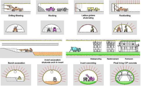
Monitoring-based adaptivity is also presented as a core “element” of NATM: potential deformations must be monitoredusingsophisticatedinstrumentationembedded in lining, ground, and boreholes, and additional supports are installed when movements are observed and support demands change.[5, 9, 13] Practical execution sequences used in NATM training materials similarly embed monitoring within the recurring excavation cycle that includes profile marking and drilling, blasting and mucking, face mapping/classification by a geologist, installationofinitialsupport,andregularmonitoring.[3]
2.3 Role of the rock mass as a structural element
A core statement across sources is that NATM mobilizes the inherent strength or self-supporting capability of the ground so that the rock mass contributes to support, achieving economy in support installation while maintaining safety by limiting loosening and excessive deformation.[1, 8, 9] Operationally, this concept is linked to immediate shotcrete protection just behind the face
advance and to flexible combinations of reinforcement (rockbolts,wiremesh,steelribs)thatformaconfinement “ring” and reduce deformation rather than simply increasingliningthickness.[1,9,13]
2.4 Primary and final lining concepts
NATM practice is frequently described as a dual-lining approach in which initial (primary) support is installed earlyanda final concreteliningisinstalledlater,typically after deformations of the primary support have reached an acceptable and decreasing trend.[2, 12] Project documentationforthe Wardha–Nandedtunnel statesthat a second lining concrete final lining shall be installed later, and that initial lining is installed immediately after excavation roundlengthisachieved,includingwiremesh, shotcrete,latticegirder/ribs,andthenrockbolting.[2]
This dual-lining concept is commonly associated with incorporation of waterproofing between linings, as SEM/NATM references describe a waterproofing membrane inserted between initial shotcrete and final cast-in-place concrete lining, and training material describes waterproofing membranes laid between primary and final lining with polymeric materials such as PVCandHDPE.[3,8]
3. Rock mass classification systems for tunnel design
Across both project and literature sources, rock mass classification is treated as an operational decision tool linking observed ground conditions to support pattern selection and allowing support to change with geological conditions during construction.[5, 7] In the Wardha–Nanded project, rock mass classification is explicitly used to define five main rock mass categories for tunnel and portal-slopesupportdesign,andRMR(Bieniawski)andQsystem (Barton et al.) are stated as the primary empirical systemsusedtodefinegenericrockclasses.[2]
3.1 Rock Mass Rating system
RMR is described in supporting literature as an empirically based system divided into six empirical parameters whose rating is used to classify rock strength and infer support requirements for underground openings.[6] TheWardha–Nandedprojectdocumentation describes grouping of the rock mass into classes depending on strength, RQD, joint parameters, groundwater condition, and stress state, and provides an
International Research Journal of Engineering and Technology (IRJET) e-ISSN: 2395-0056
Volume: 13 Issue: 04 | Apr 2026 www.irjet.net p-ISSN: 2395-0072
example that fractured basalt has an RMR value in the range20–25atPortal2conditions.[2]
TheuseofRMRinDeccantrapcontextsisalsoreflectedin tunnelling performance studies that relate excavation method performance to RMR ranges, reporting maximum TBM performance in RMR range 40–75 in a Deccan trap tunnelcasestudy,whichunderscoreshowRMRisusedas a proxy for rock mass quality and expected excavation response.[16]
3.2 Q-system
The Q-system is described as being developed at the Norwegian Geotechnical Institute (NGI) in 1974 and later modified, and it is treated as an empirical rock mass classification approach used in tunnel design alongside RMR.[6] Project documentation also identifies the Qsystem as a key method for defining generic rock classes andimpliesitsuseforclass-basedsupportselectionalong thealignment.[2]
In construction-stage applications, the Q-system is explicitly linked to quantitative description and classificationunderIndianStandards,withonecasestudy reporting classification performed under IS 11315 and IS 13365 “as per Q system (Barton, 1974)” during construction-stage mapping.[17] The same case study reports the proportion of rock mass classes encountered (e.g., 76% Class II good rock, 18% Class III fair rock, 6% Class IV poor rock), illustrating how Q-based classes can be used to communicate expected and encountered groundconditionsovertunnellength.[17]
3.3 Geological Strength Index
A tunnel-classification review source lists GSI among commonly used rock mass characterization systems alongsideRMR and Q,indicatingits roleasan established optionintunnelconstructionclassificationpractice.[18]
3.4 Comparison and applicability to Indian conditions
The comparative evidence in the included sources supports four practical comparison points: (i) RMR and Q are both empirical systems based on component parametersderivedfromavailablegeologicaldatasuchas joint frequency and intact UCS, (ii) construction-stage mapping can implement IS-based quantitative description and classification using Q-system procedures, (iii) classification inputs are uncertain and may benefit from probabilistic treatment rather than deterministic single values,and(iv)classificationschemesmayrequirecaution or modification in volcanic rock masses due to features such as columnar jointing and high porosity zones.[4, 17, 19]
Table 1. Summarycomparisonofrockmassclassification approacheshighlightedinthereviewedsources.
System Role in tunnel design decisions
RMR Used to define generic classes of rock for tunnel and slope support design in the Wardha–Nanded project.[2]
Qsystem Used (with RMR) to define genericrock classes and select support patterns; usedwithIS 11315 and IS13365for constructio n-stage classificatio n as per Qsystem procedures. [2,17]
GSI Listed among commonly used systems in tunnel constructio n classificatio n practice alongside RMR and Q.[18]
Inputs or structure emphasizedin sources
Empirical method described as divided into six empirical parameters for rating and support type inference.[6]
Notes for volcanic and basaltic rock masses
Basalt example shows fractured basalt at Portal 2 with RMR 20–25, illustrating poorquality rock mass conditions at a water-affected portal area.[2]
Developed at NGI in 1974 and modified; used empirically with rock classes reported as proportions along tunnel length in a case study.[6, 17]
Sources state Qsystem needs adjustmenttoreduce the impact of columnar jointing in basalt lava and that classification schemes may need modification for volcanicrockmasses and should be used with caution in highly porous units.[4]
Used as a recognized classification framework in tunnel construction literature listings (no parameterizat ion provided in the quoted excerpt).[18]
4. Tunnel support system design
Volcanic-rock variability is emphasized as requiring characterisation of porosity and alteration, indicating thatanyclassification approach must accommodate strong spatial and temporal variabilityinvolcanic units.[4]
NATM support is consistently described as a staged system in which initial support is installed immediately after excavation to prevent collapse or excessive deformation and to control loose rock falls, with subsequent permanent support (often concrete lining)
International Research Journal of Engineering and Technology (IRJET) e-ISSN: 2395-0056
Volume: 13 Issue: 04 | Apr 2026 www.irjet.net p-ISSN: 2395-0072
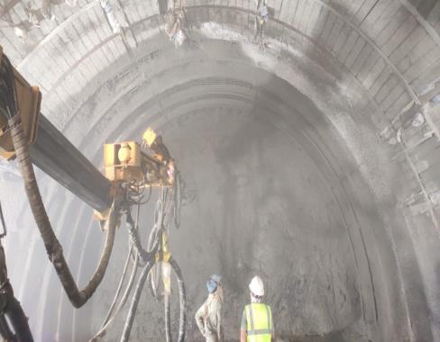
installed later as conditions stabilize.[2, 3] Both project documentsandexternalsourcesemphasizethatshotcrete is a key support component because it can provide interlocking and continuous support and can be applied rapidly to protect the excavation directly behind the face advance.[8,13]
Project documentation specifies that shotcrete design for slopesandtunnelswillbecarriedoutasperIS15026and IS 456, using FEM analysis to decide thickness and grade, and it specifies minimum shear strengths: plain shotcrete at least 3 MPa and reinforced shotcrete (wire mesh or SFRS) at least 5.5 MPa.[2] Training material defines shotcrete as wet concrete sprayed onto tunnel walls and roof, which aligns with NATM’s immediate protection conceptstatedinbroaderNATMreferences.[3,13]
SFRS is described as sprayed concrete incorporating steel fibres to improve mechanical properties, and the training documentenumeratesbenefitsincludingimprovedtensile and flexural strength (crack bridging), improved toughness and energy absorption (resistance to impact and seismic loads), reduced cracking, simplified construction (sometimes eliminating traditional steel mesh),andimproveddurabilitywithproperprotection.[3]
4.2 Rock bolts and anchoring systems
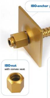
Project documentation states that fully grouted or endanchoredrockbolts/anchors,orspotbolting,usingFE500 grade steel are commonly proposed for slopes and tunnels, and that initial lining installation is completed withrockboltingshortlyafterexcavationroundlength.[2] Trainingmaterialdescribesrockboltsaslongsteelanchor rods installed into rock for stability and further describes grouted rock bolts as embedded in cementitious or chemical grout, providing improved load transfer via strongerbondbetweenboltandrock.[3]
4.3 Lattice girders and steel ribs
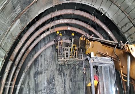
Projectdocumentationidentifieslatticegirder/ribsamong initial support elements installed immediately after excavation together with shotcrete and wire mesh, and it statesthatlatticegirderdesignwilluseempiricalmethods and site-specific simulation using Phase2/RS2 FEM analysis.[2] Training material describes steel ribs/sets/latticegirdersascurvedsteelframessupporting weak ground and notes they are often combined with shotcrete, consistent with staged support concepts in NATMsources.[3]
4.4 Forepoling and advance support
Pre-support measures are presented in contemporary SEM/NATM practice as including dewatering, grouting, ground freezing, and spiling to widen applicability in difficult grounds and increase stand-up time prior to or during tunnelling.[8] In adverse ground experiences, forepoling is described as being adopted in response to changes in backflow water colour and penetration rate, withinstallationof25mmdiameterforepolingrodsatthe crown level and spacing adjustments in very critical reaches, illustrating a monitoring-triggered advance supporttactic.[20]
Technical literature further interprets rock bolting as producingpressurebeamandartificialarchingaroundthe excavation periphery when installed with immediate supportafterexcavation,anditemphasizesbondstrength mechanisms between bolt, grout,androck andthe role of pull-outtestsinquantifyingbondingcapacityandderiving stiffnessandload-bearingcapacityparameters.[6]
International Research Journal of Engineering and Technology (IRJET) e-ISSN: 2395-0056
Volume: 13 Issue: 04 | Apr 2026 www.irjet.net p-ISSN: 2395-0072
4.5 Final lining design
Project documentation states that a second lining concrete final lining shall be installed later and that the final lining is designed to sustain all loads without considering the load capacity of the primary lining, representingaconservativestructuralassumptionforlong-term capacity.[2] Thesameprojectdocumentationdefinesastableconditioncriterionfortheprimaryliningasadisplacementrate of less than 3 mm per month before proceeding under the observationalframeworkofstagedsupportdecisions.[2]
Table 2. Supportelementsandselectedspecifications statedinprojectandtrainingdocuments.
Support element FunctioninNATM supportcycle Selected specifications or design notes from sources
Shotcrete Installed as part of initial lining immediatelyafter excavation to protectwallsand roof and to control deformation and fall of loose material.[2,3,13]
Rock bolts/anchors Installed to stabilize ground and complete initial lining support; grouting improves bond and load transfer.[2,3]
Lattice girders /steelribs Provide framed support in weak ground and work in combination with shotcrete; part of initial lining immediatelyafter excavation where required.[2,3]
Waterproofing membrane (between linings) Supports durability by preventing water ingress and is placed between primaryandfinal lining in duallining systems.[3, 8]
Designed per IS 15026 and IS 456 with FEM used to decide thickness/grade.[2] Plain shotcrete shear strength ≥ 3 MPa; reinforced/SFRS shear strength≥5.5MPa.[2]
Deccan basalt terrain is described in the project documentation as the setting for the entire region of the Wardha–Nanded tunnel alignment, with basaltic lava flows of Upper Cretaceous to Lower Palaeocene age occupyingmajorportionsofthearea.[2] Bothprojectand training sources describe a typical flow architecture in whichvesicularbasaltoccursatthetopandmassivebasalt at the bottom, while the massive basalt is described as fractured and jointed, indicating that intact strength and rock mass quality may diverge strongly within short verticalorlateraldistances.
5.1
TheDeccanbasaltisadditionallycharacterizedinbroader geological sources as a large flood basalt province coveringapproximately500,000km(\phantom{0}^2)and consisting of multiple layers of solidified basalt with cumulativethicknessexceeding2,000minsomeaccounts, highlighting the scale of layered volcanic stratigraphy relevant to tunnel planning across the province.[21] The structural and facies variability of Deccan basalt sequences is supported by critical-zone studies reporting multiple lava flows separated by interflow ‘bole’ horizons formed byinsituweatheringofflowtopsduringeruptive quiescence,indicatingthatweak,weatheredhorizonsmay recursystematicallybetweenstrongerflowinteriors.[10]
5.2
FE 500 steel fully grouted/end-anchored or spot bolting is proposed in the project documentation.[2]
Lattice girder design to use empirical methods and Phase2/RS2 FEM simulationsaccordingto project documentation.[2]
For the Wardha–Nanded tunnel alignment, the UCS of intact rock mass is reported as 150–220 MPa, indicating high intact strength typical of competent basalt, yet the project documentation simultaneously reports that at Portal 2 fractured basalt has RMR 20–25 and that the alignment is expected to pass through multiple rock classes with classes III and IV most commonly encountered.[2] Training material reports that along the tunnel alignment basaltic rocks are present with weatheredoutcropsatthesurface,whilestrong,hard,and highly fractured basalt is expected at formation level, reinforcingtheconceptofvariablerockmassqualityeven whenintactstrengthishigh.[3]
Materials listed include PVC and HDPE sheets; installationdescribedas between primary and finallining.[3]
The variability of volcanic rock masses is further emphasized in volcanic tunnelling literature, which notes that volcanic rock masses can range from high-porosity, clay-rich, fractured, soil-like material to low-porosity, high-strength, brittle, massive rock, and that porosity can negatively impact uniaxial compressive strength and Young’s modulus parameters central to excavation design.[4] This variability supports the need for rock mass characterisation that includes not only mechanical properties (strength and stiffness) but also petrophysical propertiessuchasporosityandgeologicalconditionssuch as alteration, which can vary strongly within volcanic stratigraphy.[4]
International Research Journal of Engineering and Technology (IRJET) e-ISSN: 2395-0056
Volume: 13 Issue: 04 | Apr 2026 www.irjet.net p-ISSN: 2395-0072
5.3 Groundwater and hydrogeological challenges
Hydrogeological challenges in basalt settings are prominentintheWardha–Nandedprojectdocumentation, which reports that Portal 2 area is relatively flat with surface streams present and high groundwater ingress, andthatPortal 2 iscompletelyfilledwithwater,implying that portal works may require extensive dewatering and additionalwatermanagementarrangements.[2] Thesame project documentation notes that geological mapping at such a water-filled portal location may not be possible unless water is drained so that the rock section is visible, emphasizing practical constraints on characterization and constructionstaginginhigh-waterconditions.[2]
Independent studies of Deccan basalt hydrogeology support the importance of permeable fracture networks and layered facies contrasts, reporting evidence for deep groundwater percolation in Deccanbasaltand notingthat although non-massive parts of lava flows facilitate groundwater storage, water-saturated permeable fractures in massive basalt can favour deep hydrological networks.[22]
6. Numerical modelling for tunnel analysis
NATM-related guidance emphasizes that engineering calculations and numerical simulations are based on simplified models whose validity must be carefully reviewed, and that results must be verified by geotechnical measurements and observations during construction with modifications made as needed, consistent with observational tunnelling practice.[1] This verification principle is aligned with project documentation stating that 3D monitoring data helps optimize design during construction and that stable conditions for primary lining are checked using a displacement-rate criterion before proceeding with final liningdecisions.[2]
The Wardha–Nanded project documentation states that tunnel stability analysis will be carried out using Phase2/RS2 as a continuum finite element program with Mohr–Coulomb yield criteria to estimate stresses and deformations around the tunnel, providing a defined modellingapproachforsupportassessment.[2] Thesame documentation specifies that the numerical model is conceived as a plane strain model with external boundaries located about three times the opening size from excavated tunnel boundaries, indicating a boundary placementruleusedinthedesignmodellingworkflow.[2]
Volcanic-rock tunnelling literature additionally notes that numerical modelling of tunnel behaviour requires full failure criteria such as Mohr–Coulomb or Hoek–Brown, and that failure criteria and parameters depend strongly on texture, porosity, and alteration in volcanic rocks, reinforcingtheneedtointegrategeologiccharacterization withmodellingassumptionsandparameterselection.[4]
Withinthe Wardha–Nanded project,Phase2/RS2isstated astheprimarynumerical toolforcontinuummodelling to estimate stresses and deformations and check stability, and the same project documentation also states that lattice girder design will include site-specific simulation using Phase2/RS2 based on FEM analysis, indicating consistentFEMtoolusageacrosssupportcomponents.[2]
The project documentation further states that seismic loadings are not considered in analysis and design of the primarysupportsystem,whilealsostatingseparatelythat the project area lies in seismic zone III and that portal slopes and portal linings should be checked for seismic forces, highlighting a differentiated seismic design scope betweendeeptunnelprimarysupportandportal/cut-andcovercomponents.[2]
Beyond continuum FEM, the Wardha–Nanded project documentation states that discontinuity analysis and wedge formation/tunnel stability checks will be performed using Unwedge, and that kinematic analysis of planarandwedgeformationsandtopplingfailureswillbe checked using Dips if necessary, representing a combined continuum–discontinuity workflow for stability assessment.[2]
Construction-stage evidence from other tunnel case studies reinforces the engineering relevance of discontinuities and shear zones, reporting mapped joint setsandmultipleshearzonesassociatedwithseepageand overbreak cavity formation during drill-and-blast excavation, and linking such zones to Q-value variations and adverse ground reaches that required modified supportmeasures.[17]
Water management is treated as a central durability and constructability concern in NATM practice because water ingresscancompromisestructuralintegrityandlong-term durability, and waterproofing membranes are described as being installed between primary and final lining using polymeric materials such as PVC and HDPE sheets or synthetic rubber.[3] SEM/NATM literature similarly describesa dual-liningcross sectionwitha waterproofing membrane inserted between initial shotcrete and final cast-in-placeconcretelining,establishinga general NATM waterproofing architecture consistent with the training materialdescription.[3,8]
Project documentation for the Wardha–Nanded tunnel states that drainage systems must be designed for both construction and operating phases, indicating that temporary construction drainage and long-term operational drainage must be integrated in design
International Research Journal of Engineering and Technology (IRJET) e-ISSN: 2395-0056
Volume: 13 Issue: 04 | Apr 2026 www.irjet.net p-ISSN: 2395-0072
intent.[2] The tender drainage design described in the samedocumentation includes150mmdiameterside wall pipes on both sides to manage groundwater ingress, rectangular drains on each side to handle surface water, anda400mmdiametermaincollectorpipebelowthebed concrete receiving flow from both surface and side drains.[2]
7.2 Permanent drainage systems
Because portal 2 conditions include significant groundwater seepage and surface streams, project documentation states that perforated drainage pipes with geotextile along portal slopes may be necessary, linking observedhydrogeological conditionstorequireddrainage interventions aimed at reducing pore pressure and improvingstability.[2] Thesamedocumentationspecifies provision of a flushing system at suitable intervals, and it also calls for an oil and silt separator to isolate particles before routing water to a sewage treatment plant, reflecting operational and environmental management considerationsfortunneldrainagedischarge.[2]
7.3 Waterproofing membranes
Trainingmaterialemphasizesthatwaterproofingprevents water ingress when combined with a waterproof membrane and is installed between primary (temporary) and final lining, and it lists common waterproofing materials including PVC and HDPE sheets and related polymericmembranes.[3]
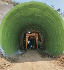
8. Portal design and slope stability
Portal conditions strongly influence construction risk and drainage requirements in NATM tunnels, as the Wardha–Nanded project documents sharply different portal environments,includinga50mhighportalslopeatPortal 1 and a waterlogged, stream-influenced portal area at Portal 2.[2] The same project documentation situates Portal1atchainage55+151mfoundedonmassivebasalt, with completely weathered rock/soil at the surface gradingwithdepthtohardintact,strong,highlyfractured basaltic rock at the portal location, illustrating vertical weathering variability relevant to cut slope stability and portalsupportdesign.[2]
8.1 Portal slope stability analysis methods
Project documentation indicates that portal slopes and portal linings are checked for seismic forces because the project area belongs to seismic zone III, establishing that portal and cut-and-cover components include seismic checks even when primary support may omit seismic loadinginanalysis.[2] HighgroundwateringressatPortal 2 and potential submergence requiring extensive dewatering arrangements are reported as specific portal risks, reinforcing that slope and portal stability design must account for pore pressure and water control measuresatthatlocation.[2]
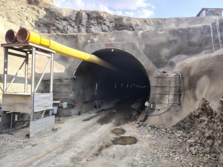
8.2 Kinematic analysis
The Wardha–Nanded project documentation states that kinematic analysis of wedge formations (planar and wedge) and toppling failures will be checked by discontinuity analysis using Dips software if necessary, reflectingakinematicanalysisapproachfordiscontinuitycontrolled failures at portal slopes and potentially at tunnelfaces.[2]
8.3 Global stability assessment
Projectdocumentationstatesthatstabilityanalysiswillbe carried out using Phase2/RS2 with Mohr–Coulomb yield criteria to estimate stresses and deformations and to check tunnel stability, and this continuum modelling approach can also support global stability assessments whereslope–structure interactionorstressredistribution aroundexcavationsisimportant.[2]
9. Discussion and future directions
The reviewed sources collectively indicate that NATM effectiveness depends on a closed-loop framework that integrates (i) continuous monitoring and interpretation, (ii) flexible modification of support and construction sequence, and (iii) rigorous safety and risk management processes supported by contracts and decision-making structures appropriate for observational construction.[1, 9] A guideline-oriented source stresses that even with extensive investigation programs and up-to-date design, uncertainties remain in ground model, properties, and behaviours, and therefore continuous information
International Research Journal of Engineering and Technology (IRJET) e-ISSN: 2395-0056
Volume: 13 Issue: 04 | Apr 2026 www.irjet.net p-ISSN: 2395-0072
collection and targeted monitoring programs with warning/alarm criteria and mitigation measures are requiredaspartofgeotechnicalsafetymanagement.[1]
ForDeccanbasaltandvolcanicrockmasses,theliterature indicatesthatclassificationschemesmayneedadjustment (e.g., Q-system adjustment for columnar jointing) and shouldbeapplied withcautioninhighlyporous orpoorly lithified volcanic units, and that advance borings in the tunnel face are important for reducing the risk of unexpected poor geological conditions.[4] This caution is consistent with broader volcanic-rock tunnelling observations that rock mass characterisation must address strong variability and anisotropy and should include porosity and alteration in ground models, while numerical modelling must use failure criteria sensitive to texture and alteration effects and must be validated againstobservations.[1,4]
Asecondcross-cuttingthemeisthetendencyfordesigned support patterns to be exceeded during construction due to geological conditions, as one study notes that support patterns used during construction are frequently heavier than designed, increasing cost, and proposes scoring methods that align preliminary investigations and construction-stage classification criteria including negative points for water seepage and deterioration.[7] Complementary work showsthatdeterministic rock mass classification can be biased relative to probabilistic classification distributions when inputs are uncertain, motivating probabilistic approaches (e.g., Monte Carlo sampling) to quantify classification uncertainty and supportsystemselectionriskovertunnellength.[19]
Finally, project and case-study evidence emphasizes that groundwater and seepage can dominate schedule and safety risk in basaltic tunnels, with examples of Portal 2 waterlogging and high ingress in the Wardha–Nanded tunnel, and independent Deccan trap tunnelling experience reporting that heavy ingress of water was a main impediment to achieving targeted progress and requiring extensive grouting before final lining to control seepage.[2,23]
10. Conclusions
NATM is consistently framed as an observational and monitoring-driven approach in which support and construction sequence are optimized based on measured deformation and mapped ground conditions, rather than fixedpre-definedsupportprescriptions.[2,5]
Dual-lining concepts early installation of primary support followed by later installation of concrete final lining are explicitly used in the Wardha–Nanded NATM tunnel and are widely described in SEM/NATM literature, often with waterproofing membranes between initial shotcreteandfinalconcretelining.[2,3,8]
In practice, rock mass classification is central to NATM decision-making and is used to define rock classes and
select support patterns, with the Wardha–Nanded project explicitly using RMR and Q-system frameworks and expecting predominant class III and IV ground while encountering portal-specific poor RMR (20–25) fractured basaltatPortal2.[2]
Project documentation and training materials emphasize primary support systems built around shotcrete, rock bolts/anchors, and lattice girders/steel ribs installed immediately after excavation, with IS-based shotcrete design and quantified minimum shear strength requirementsforplainandreinforced/SFRSshotcrete.[2]
Numerical modelling in the Wardha–Nanded project explicitlyusesPhase2/RS2FEMwithMohr–Coulombyield criteria and plane strain boundary placement rules, supplemented by discontinuity and kinematic tools such as Unwedge and Dips, reflecting a combined continuum anddiscontinuitystabilityassessmentworkflow.[2]
Deccan basalt tunnelling requires explicit treatment of layered flow architecture (vesicular tops and massive bases) and rock mass variability (fracturing, weathering) alongside hydrogeological controls, as evidenced by portal-specific high groundwater ingress and water-filled portal conditions requiring drainage and dewatering measures.[2,3]
Future NATM improvements for basalt and volcanic terrains are strongly linked to reducing uncertainty through targeted monitoring and safety management, careful verification of modelling results against measurements,andcautiousormodifieduseofrockmass classification where volcanic variability (porosity, alteration, jointing) challenges deterministic design assumptions.[1,4]
References
1. M. Villeneuve (2021) Challenges of Tunnelling in Volcanic Rock Masses. BHM Berg- und Hüttenmännische Monatshefte. https://doi.org/10.1007/s00501-021-01175-2
2. NewAustrianTunnellingMethod|EncyclopediaMDPI. https://encyclopedia.pub/entry/28107
3. VishalM.Meshram,Dahale P.P,T.M.S,Manekar G.G (2020)AdvancementofConventionalAnchorSupport SystemthroughUseofNATMandNMTApproachfor Underground Drift Stability. https://doi.org/10.29042/2020-10-1-76-83
4. M.Kimura (2010) RESEARCHINTO RATIONALROCK MASSCLASSIFICATIONDURINGSURVEYANDDESIGN USING SCORING POINTS FOR TUNNEL CONSTRUCTION. GEOINFORMATICS. https://doi.org/10.6010/GEOINFORMATICS.21.137
5. Nasri Munfah;Vojtech Gall;Steffen Matthei Recent TrendsinConventionalTunneling(SEM/NATM)inthe US. https://www.gzconsultants.com/wpcontent/uploads/WTC2016-0401.pdf
International Research Journal of Engineering and Technology (IRJET) e-ISSN: 2395-0056
Volume: 13 Issue: 04 | Apr 2026 www.irjet.net p-ISSN: 2395-0072
6. Contributors to Wikimedia projects New Austrian tunnelingmethod.https://en.wikipedia.org/wiki/New_ Austrian_tunnelling_method
7. Seismic characterization of lava flow facies in the critical zone of the deccan traps using shear wave velocity models | Scientific Reports. http://nature.com/articles/s41598-025-13638-4
8. ContributingAuthorUnderstandingtheNewAustrian TunnelMethod(NATM).https://tunnelingonline.com/un derstanding-the-new-austrian-tunnel-method-natm/
9. Untitled.https://www.rockmass.net/ap/39_Palmstrom _on_NATM.pdf
10. adminNATM – TheNewAustrianTunnelingMethod. https://civilengineerblog.com/natm-new-austriantunneling-method/
11. TheNewAustrianTunnellingMethod. Seong-WonLee A Study of Vibration Reduction Effects of TBM and NATM Parallel Construction Methods according to TunnelDepthandSize.https://www.mdpi.com/20763417/13/6/3492
12. <<<123>>>EstimationofthePerformanceofthe Tunnel Boring Machine (TBM) Using Uniaxial Compressive Strength and Rock Mass Rating Classification(RMR) – ACaseStudyfromtheDeccan Traps,India. https://www.geosocindia.org/index.php/jgsi/article/vi ew/86891/0?articlesBySameAuthorPage=2
13. D. Ramakrishna, N. R. Rao (2023) Geotechnical Investigation and Monitoring of Underground Excavation of Tunnel-2 in Srisailam Left Bank Canal TunnelProject(AMRP),Nalgonda District,Telangana, India. Journal of Geosciences Research. https://doi.org/10.56153/g19088-022-0092-19
14. H.Hussin,M.H.Arifin(2023)Rockmassclassification for rock mass in tunnelling and underground excavation-Development,limitationandwayforward. Bulletin of the Geological Society of Malaysia. https://doi.org/10.7186/bgsm75202303
15. MarteGutierrez,GauenAlexander(2024)Probabilistic Rock Mass Classification from Prior Construction for theFutureExtensionofaTunnel.WorldCongresson Civil, Structural, and Environmental Engineering. https://doi.org/10.11159/icgre24.127
16. D.Rawat,A.Naithani,L.G.Singh,etal(2016)Tunneling through adverse geological conditions in granitic terrain.https://doi.org/10.2991/RARE-16.2016.41
17. OCHUKO1 Microsoft Word - Verma et al pdf. https://interesjournals.org/articles/influence-ofwater-content-on-geotechnical-properties-of-deccanbasalt-maharashtra-india.pdf
18. Deepjyoti Goswami|Sukanta Roy|Vyasulu V. Akkiraju PetrophysicalandfluidtransportpropertiesofDeccan trapbasaltsfromanalysisofgeophysicalwelllogsina 3km scientific borehole at Koyna, India | Earthdoc. https://www.earthdoc.org/content/journals/10.1002/ nsg.70030
19. [PDF]Performanceoftunnelboringmachineinbasaltic DeccanTraprock. https://api.taylorfrancis.com/content/chapters/oaedit/download?identifierName=doi&identifierValue=1 0.1201%2F9781003645955-67&type=chapterpdf