Grade 9 • Study Guide Technology

Owned and published by Optimi, a division of Optimi Central Services (Pty) Ltd.
7 Impala Avenue, Doringkloof, Centurion, 0157 info@optimi.co.za www.optimi.co.za
© Optimi
Apart from any fair dealing for the purpose of research, criticism or review as permitted in terms of the Copyright Act, no part of this publication may be reproduced, distributed, or transmitted in any form or by any means, electronic or mechanical, including photocopying, recording, or any information storage and retrieval system without prior written permission from the publisher.
The publisher has no responsibility for the persistence or accuracy of URLs for external or third-party internet websites referred to in this publication, and does not guarantee that any content on such websites is, or will remain, accurate or appropriate.
There are instances where we have been unable to trace or contact the copyright holder. If notified, the publisher will be pleased to rectify any errors or omissions at the earliest opportunity.
Reg. No.: 2011/011959/07

PREFACE
Technology can be defined as the use of knowledge, skills, values and resources to meet people’s needs and wants by developing practical solutions to problems, taking social and environmental factors into consideration.
INTRODUCTION
This book has been developed to support the new Curriculum and Assessment Policy Statement (CAPS). The contents have been organised in topics stipulated by the CAPS. The authors have strived to make this book as comprehensive as possible within the framework of the curriculum.
The main aim of this book is to equip learners with a sound basic knowledge of various aspects of technology. It will not only assist them to master technology, but also to put theory into practice.
We took special care to:
• make the contents learner friendly
• attractively illustrate the contents
• make the contents industry related
• provide relevant and stimulating activities
• provide a variety of additional activities for practice at the end of each unit
• motivate learners to explore the different fields in technology
The Technology Study Guide is supported by the Technology Facilitator’s Guide.
STUDY TIPS
• Don’t postpone studying until the night before the examination or test. Compile a timetable so that you can manage your time effectively.
• Choose a suitable study method that suits your needs and practise it. Study skills have to be practised if you want to perform well.
SAMPLE
• You can use any study method to master technology, but to achieve good results, the following principles are suggested:
1. Summary Get an overview of the work to be studied. Read through everything quickly to see what it is about.
2. Questions
Prepare questions about the work that you can use to study: Why? How? What? For example: what are drawing standards? How are they used?
3. Read and learn Read and study these questions very carefully.
4. Recite Say the questions and answers out loud without using your book.
5. Check If you understand, know and repeat the work, check your answers against the content in the study guide. Keep on studying until you remember everything.
6. Repeat Repeat the work every day.
TERM 1
UNIT 1: Design skills

Learning objectives
After you have completed this unit, you must be able to demonstrate your knowledge and understanding of:
Communication
• Drawing conventions
• First angle orthographic projection
• Artistic drawing
• Isometric projection
Introduction
Graphics are images visible on paper, walls, canvas, stone, etc. Graphic forms include drawings, photographs, diagrams, graphs, etc.
In technology graphics are used to:
• develop ideas in the form of an initial sketch that later leads to the final design
• communicate ideas and designs in the form of a universal and accepted language
When an object is to be designed, it must be sketched and drawn to:
• give the reader an idea of the nature and appearance of the object
• give the reader specific dimensions of the object as well as the scale of the drawing
SAMPLE

IMPORTANT TERMINOLOGY
Isometric projection A three dimensional 3-D drawing that uses lines drawn at 30º.

SAMPLE
Orthographic projection A two dimensional (2-D) drawing used to produce a working drawing, usually showing three separate views of the same object.
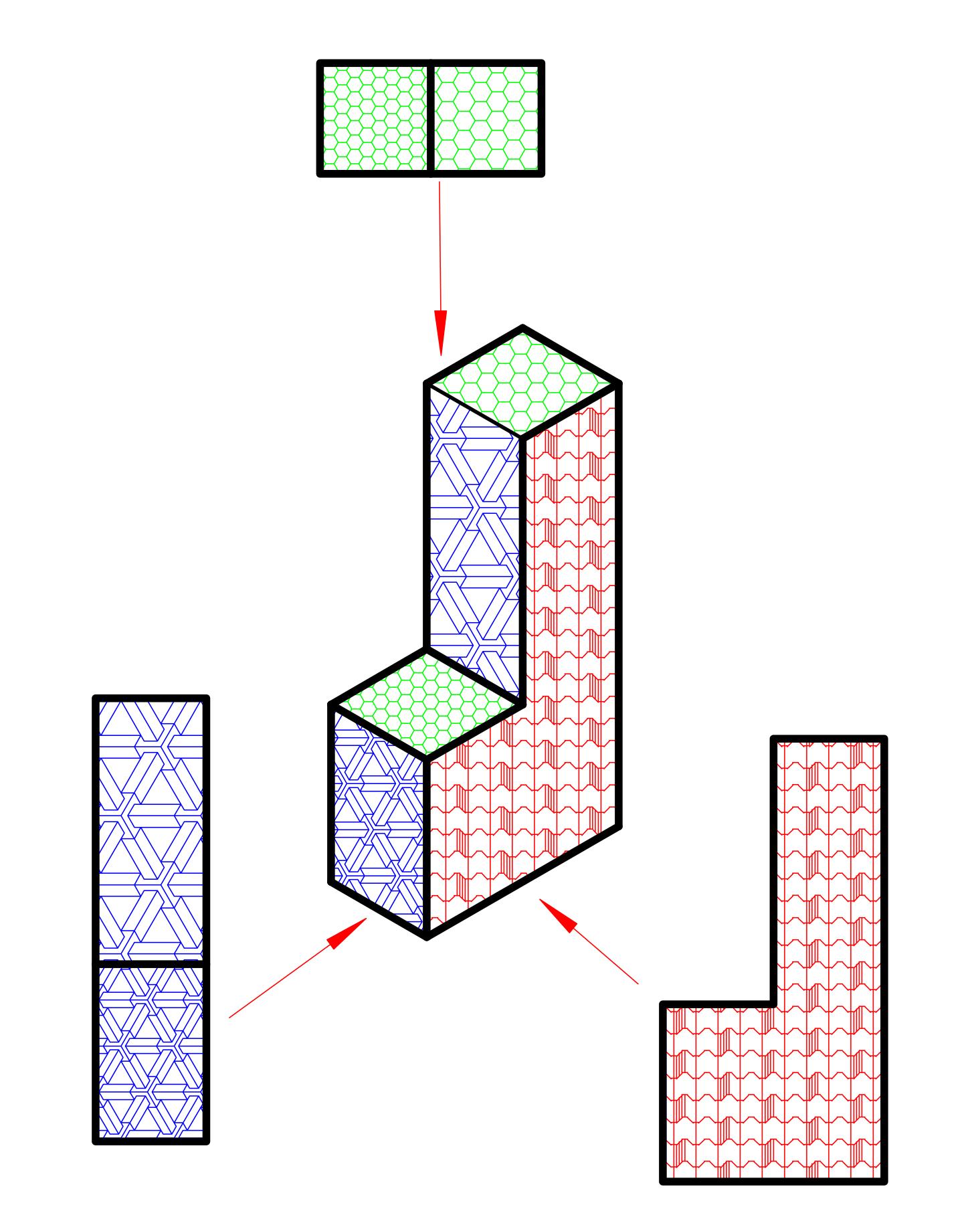
Artistic drawing When advanced techniques such as colour, texture, shading, shadows and perspective are used to create a drawing that resembles reality.

LESSON 1: Drawing conventions
Drawing conventions are necessary for communicating ideas. They enable a person to interpret an idea and form a complete picture of an object.
Learners need:
• a clutch pencil with 0.5 mm HB (a clutch pencil with 0.3 mm 2H lead is optional)
• mathematics set (drawing instruments)
• pencil, eraser, ruler and a set of drawing triangles
• A4 paper
SAMPLE
• 6 mm double-sided tape to build models
• other tools as required for the execution of the PAT as mentioned in the Facilitator’s Guide
Conventions include:
• Line types: outlines, construction lines, hidden detail and centre lines
• Scale: size on paper in comparison to the actual size, e.g., 1:100
• Dimensions: measurements of sides in millimetres (mm)
1.1: Types of lines in drawings
Using different types of lines gives the viewer a clear picture of the object. Different lines emphasise different parts of a drawing and convey specific information about the object, such as folding lines or hidden detail.
1.1.1 Outlines (dark)
Example of line Description Uses Example in sketches

Draw with a 0.5 mm pencil.
• thick
• dark
• continuous
1.1.2 Construction lines (faint)
• outlines of drawings
• finishing of drawings

Example of line Description Uses Example in sketches
• very thin
• light (faint)
• continuous
Draw with a 0.3 mm pencil with 2H lead.
(A 0.5 mm pencil may also be used.)
1.1.3 Hidden detail (dashed)
SAMPLE
• folding or bending lines
• dimensions
• construction lines

Example of line Description Uses Example in sketches

Draw with a 0.3 mm pencil with 2H lead.
(A 0.5 mm pencil may also be used.)
• thin
• medium (faint)
• dashed lines
• hidden detail (information)

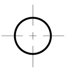
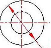
1.1.4 Centre lines (chain)
Example of line Description Uses Example in sketches

Draw with a 0.3 mm pencil with 2H lead.
(A 0.5 mm pencil may also be used.).
• thin
• medium (faint)
• dashed lines, long and short
• centre lines
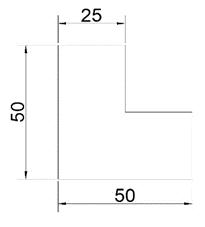
1.1.5 Dimension lines for measurements
Example of line Description Uses Example in sketches

Draw with a 0.3 mm pencil with 2H lead.
(A 0.5 mm pencil may also be used.)
• very thin
• medium (faint), continuous with arrow heads on both sides with measurement indication
• always indicate measurements in millimetres (mm)
• length, width, height of the object
• size and measurements of levels
1.1.6 Wavy lines
SAMPLE
Example of line Description Uses Example in sketches

Draw with a 0.3 mm pencil with 2H lead.
(A 0.5 mm pencil may also be used.)
• medium (faint)
• evenly drawn with freehand
• indication ofcuts in a shaft

1.1.7 Horizontal
Description
Horizontal refers to the horizon, parallel to the ground surface.


1.1.8 Vertical
Description
Vertical refers to an object that is 90° to the ground surface; perpendicular.

1.1.9 Arrow head
Description Example of line
An arrow head has a specific size. It is usually 3 mm in length and depends on the size of a drawing. The width or thickness of the arrow head is 1 mm.
SAMPLE

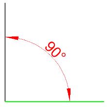
The pointed end of an arrow head starts on an extension line that indicates the angles that it is measured between.
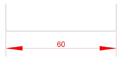
Take note of the following on extension lines and measurements in relation to dimension lines.
Description
• Centre lines can be used as extension lines as well.
• In orthographic projections extension lines are always perpendicular (90°) to a dimension line or drawing line.
Extension lines
Measurements
• An extension line usually starts 2 mm from a drawing line that completes the drawing.
• Extension lines are usually 12 mm long.

• The dimension indicator (measurement indicator in millimetres) must be printed 1 mm from the dimension line.
• The measurements (in millimetres) must be printed 3 – 5 mm high.
• Dimensions are read from left to right.
The different lines and their uses are shown in the drawing below
Example 1
A Outlines
B Dimension line
C Centre line
D Hidden detail
E Construction line

Example 2
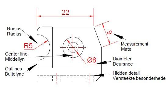
Centre line
1.2 Scale
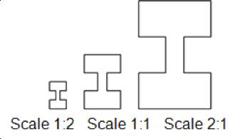
In drawings where size and dimention are important, the object is drawn according to a specific scale in milimetres(mm). A scale indicates the relationship between the drawing and the actual size of the object; e.g., 1:2.
The scale is written in a ratio, e.g. 1:2 where 1 represents the size of the real object and the 2 indicates the size of the drawing.
The scale can also be treated as a fraction, e.g.:

• 1:2 may be written as meaning it will be half of the true size.
• 2:1 may be written as meaning it will be twice the true size.

NB: 1 is always the true size.
SAMPLE

The use of different scales
Note: The block with the pattern is the true size of the object.
• 1:1 Measurements drawn according to the true size of an object.
• 1:2 Measurements are half the true size of the object (downscaling).
• 2:1 Measurements are double the true size of the object (upscaling).
• 3:1 Measurements are triple the true size of the object (upscaling).

Scales may be used in different ways because the actual size of the object does not always fit on a page. It can be drawn smaller or bigger than the actual size and this is referred to as scale.
SAMPLE




1.3 Dimensions
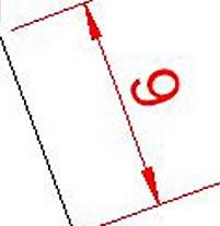
Dimensions are measurements of an object in a drawing and are always given in millimetres. The principal dimensions of an object in a drawing indicate the length, height and width or depth.
Two-dimensional drawings (2-D) reflect two dimensions with measurements.
SAMPLE

Three-dimensional drawings (3-D) reflect three dimensions with measurements.


Activity 1
The application of the different types of lines.
Instructions
1. Study the drawing below and identify the application of the different types of lines as indicated in the word bank.
SAMPLE
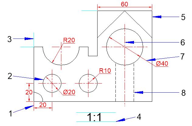
2. Complete the table below.
LESSON 2: First angle orthographic projection
The views of an object in first angle orthographic projections. First angle orthographic projections are two-dimensional drawings. In other words they are 2-D – only two dimensions are visible.
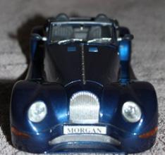
The car is used to explain the views below.

Front view
This is the view as seen from the front and is usually the view that shows the most detail.
• Comprehensive explanations of concepts in plain language.
• Interactive, fun, and practical activities with everyday objects to help learners master concepts.
• Includes drawing sheets and step-by-step instructions.
• Alphabetical list of important terminology for easy reference.
• Learners are shown how to complete the practical assessments.
• Use in school or at home.
