6 minute read
Plan Area : Section "A" 30m x 30m 30m x 30m 30m x 30m 30m x 30m 30m x 30m Section "B" 30m x 30m 20m x 20m 20m x 20m 20m x 20m 20m x 20m


Optimization of Setback Position in RC Building under Dynamic Earthquake Response
Shubham Shrivas1 , Kishor Patil2 1PG Student, Department of Civil Engineering, Sushila Devi Bansal College of Engineering, Indore (MP), India 2Professor & HOD, Department of Civil Engineering, Sushila Devi Bansal College of Engineering, Indore (MP), India
Advertisement
Abstract: Now day, tall buildings have been widely used in semi-urban and urban areas of developed and developing countries, as they provide large space for commercial or residential use. As per civil and structural Engineering concept a building consist of different discontinuity related to mass, structural geometry, stiffness and et. al. This discontinuity imparts the irregularities in the structure. Earthquake analysis performance of structure becomes really important under the effect of vertical irregularities. For this study, analysis has been carried out on five different models having same base plan area of 30.00m x 30.00m and structure height of 78.75m (i.e. G+20 Storied Structure), in which one is regular model without setbacks (Designated as Model “0”) while four other models having setbacks at different positions. The setbacks are of same plan area (20.00m x 20.00m and 10.00m x 10.00m) and of same heights as 31.50 m 26.25m and 21.00 m from the base. Storey Displacement, Maximum Storey Displacement, and Base Shear Result are evaluated. The analysis is carried out in ETABSvr.16 Software. On the basis the results is taken out are Story Displacement, Maximum Story Displacement and Base Shear, Overturning Moments of each models and at the place of setback provided. Keywords: setbacks, tall buildings, G+20 Storied Structure, vertical irregularities, ETABSvr.16
I. INTRODUCTION
In urban areas, high-rise construction has become a necessity for people. To satisfy the same need, they became popular in culture. Buildings can be broadly classified as ordinary and irregular plan buildings. A building that is symmetrical or with uniform geometry and with a constantly distributed mass is known as an ordinary building. A building can have various shapes, designs, and types of frame structures. In the same structure, when changes occur at any point in the region compared to the upper and lower floors, and the other side of the building is called an irregular building. A building that is classified as irregular, structural failure can occur due to this uncertainty, such as geometry discontinuity, mass discontinuity, load resistance rupture, and rupture in the absence of building symmetry. Structural irregularities can be classified as vertical and horizontal (plan) irregularities. Roughness in the structures can be associated with uneven distribution of mass, strength and rigidity along the height of the building. There are various types of horizontal irregularities in the building, followed by Torsional irregularities, repeating angular irregularities, overlapping ceilings with an excessive opening and notches, deviation from the plane in the vertical element, and the latter is a nonparallel system of lateral forces. Different categories of vertical unevenness are stiffness unevenness (soft number of storey’s), mass unevenness, vertical geometric unevenness, a gap in the plane in a vertical element withstanding lateral load, unevenness of strength (weak floor), floating or indirect columns, irregular modes of oscillations in two . Analysis and design of such a high-rise structure for lateral wind loads can become more difficult for a civil engineer. In this project, vertical geometric irregularity was carefully studied.
II. MODELLING AND ANALYSIS
The models can be sub-divided into three different sections i.e. Section 1: Base to G+6 stories, Section “B”: G+6 to G+13 stories and Section “C” from G+13 to G+20 stories. The setbacks have been kept at the top of Section “A” and Section “B” i.e. at stories G+6 and G+13. The geometrical properties of the structures have been shown in table 1.
Table 1: Structure Geometric Details S.No. Description Model 0 Model 1 Model 2 Model 3 Model 4 1 Plan Area : Section "A" 30m x 30m 30m x 30m 30m x 30m 30m x 30m 30m x 30m Section "B" 30m x 30m 20m x 20m 20m x 20m 20m x 20m 20m x 20m Section "C" 30m x 30m 10m x 10m 10m x 10m 10m x 10m 10m x 10m
2
4
Levels Height :Section "A" 31.50 m 31.50 m 31.50 m 31.50 m 31.50 m Section "B" 26.25 m 26.25 m 26.25 m 26.25 m 26.25 m Section "C" 21.00 m 21.00 m 21.00 m 21.00 m 21.00 m 3 Structure Height 78.75m 78.75m 78.75m 78.75m 78.75m Offsets: X-Direction First Nil 5 10 5 10 Second Nil 5 10 10 5
5 Offsets: Y-Direction First Nil 5 5 5 5 Second Nil 5 5 5 5
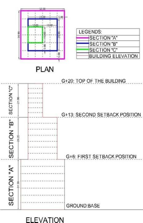
Fig 1: Model 1: Fig 2: Model 2 Fig 3: Model 3: Fig 4: Model 4: Structural Models
Fig 5: 3D view of Model 0 Fig 6: Model 1 Fig 7 : Model 2 Fig 8: Model 3 Fig 9: Model 4
A. Seismic Data and Material Properties 1) Seismic Data: Zone-4, Zone Factor: 0.24, Soil Type: Medium, Importance Factor:1.15, Response Reduction Factor:5,
Direction: Both X and Y, Eccentricity: Nil
Table 2: Structure Parameters for All Models
S. No
1 Column Size 1.a 1.b Particular
1.c 2 Column Spacing 2.a 2.b 3 Beam Size (Main) 3.a 3.b 3.c 3.d 4 Slab thickness 5 Details
Ground - G+6 400x600mm G+7 - G+13 300x500 mm G+14 - G+20 200x400 mm
X-direction 5.00 m c/c Y-direction 5.00 m c/c
Plinth Beam 250x600mm Ground - G+6 300x600mm G+7 - G+13 250x500 mm G+14 - G+20 200x400 mm 150 mm thick 20.00 KN/m3
A. Storey Displacements
III. RESULTS AND DISCUSSIONS
Table 3 : Storey Displacement In X-Direction
Story Model 0 Model 1 Model 2 Model 3 Model 4 G+20 376 334.73 356.144 349.516 344.432 G+19 371.698 323.994 343.62 337.439 333.386 G+18 365.199 306.367 324.097 318.385 315.394 G+17 356.355 281.947 297.738 292.51 290.611 G+16 345.102 251.749 265.205 260.466 259.68 G+15 331.412 217.692 228.03 224.489 224.993 G+14 315.408 181.802 189.682 187.073 188.646 G+13 298.864 154.936 160.034 158.566 161.12 G+12 283.568 145.28 146.927 145.9 148.62 G+11 266.415 133.554 133.832 133.339 135.763 G+10 247.63 119.745 119.684 119.325 121.496 G+9 227.397 104.088 103.986 103.765 105.581 G+8 205.532 86.943 86.907 86.816 88.209 G+7 182.228 68.927 68.976 68.825 69.935 G+6 159.834 53.72 53.481 53.595 54.207 G+5 139.552 46.64 46.294 46.515 46.95 G+4 117.919 39.242 38.782 39.032 39.422 G+3 95.214 31.874 31.215 31.553 31.75 G+2 71.666 24.206 23.436 23.907 23.881 G+1 47.558 16.173 15.55 15.946 15.886 GF 23.386 7.992 7.655 7.872 7.826 Ground 1.859 0.637 0.609 0.627 0.622 Base 0 0 0 0 0
Storey Displacement in Xdirection for TH-X (mm) Storey Displacement in Y-direction for TH-Y (mm)
G+18 G+15 G+7 G+10 G+12Storeys G+4 G+1 Base G+18 G+15
0 200 400 Model 4 Model 3
Model 2 Model 1 Model 0 G+7 G+10 G+12 Storeys G+4 G+1 Base Model 4 Model 3
Model 2 Model 1 Model 0
Displacement in mm
0 100 200 300 400 Displacement in mm
Fig 10: Storey Displacement in X-Direction for Th-X And Th Y
Table 4: Storey Displacement In Y-Direction (mm) Story Model 0 Model 1 Model 2 Model 3 Model 4 G+20 376 334.73 367.933 345.175 349.443 G+19 371.698 323.994 358.893 335.373 339.3 G+18 365.199 306.367 344.018 319.318 322.599 G+17 356.355 281.947 323.231 296.97 299.258 G+16 345.102 251.749 296.83 268.722 270.244 G+15 331.412 217.692 265.495 236.006 236.387 G+14 315.408 181.802 230.837 200.604 199.133 G+13 298.864 154.936 201.989 171.702 173.625 G+12 283.568 145.28 186.687 156.897 165.709 G+11 266.415 133.554 169.72 141.189 154.146 G+10 247.63 119.745 151.802 124.46 140.492 G+9 227.397 104.088 133.107 106.905 125.239 G+8 205.532 86.943 114.003 88.304 108.744 G+7 182.228 68.927 94.513 69.481 91.527 G+6 159.834 53.72 78.046 60.234 76.798 G+5 139.552 46.64 68.721 53.186 67.69 G+4 117.919 39.242 58.465 45.414 57.626
G+3 95.214 31.874 47.522 36.979 46.86 G+2 71.666 24.206 35.988 28.018 35.497 G+1 47.558 16.173 24.017 18.694 23.692
GF 23.386 7.992 11.87 9.234 11.71 Ground 1.859 0.637 0.948 0.737 0.935
Base 0 0 0 0 0