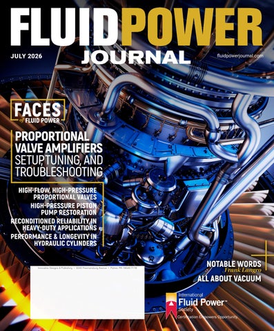
HIGH-FLOW,
HIGH-PRESSURE PISTON PUMP RESTORATION
RECONDITIONED RELIABILITY IN HEAVY-DUTY APPLICATIONS
PERFORMANCE & LONGEVITY IN HYDRAULIC CYLINDERS




HIGH-FLOW,
HIGH-PRESSURE PISTON PUMP RESTORATION
RECONDITIONED RELIABILITY IN HEAVY-DUTY APPLICATIONS
PERFORMANCE & LONGEVITY IN HYDRAULIC CYLINDERS
Designing efficient systems is about more than components and specifications—it’s about understanding how real requirements come together in the real world. By taking the time to understand the specific demands of your system, we bring decades of engineering experience and a people-first mindset to develop solutions that perform better, last longer, and fit exactly where they need to.
Have a challenge you’re working through? Call or email us today and let’s connect our engineers with your engineers.

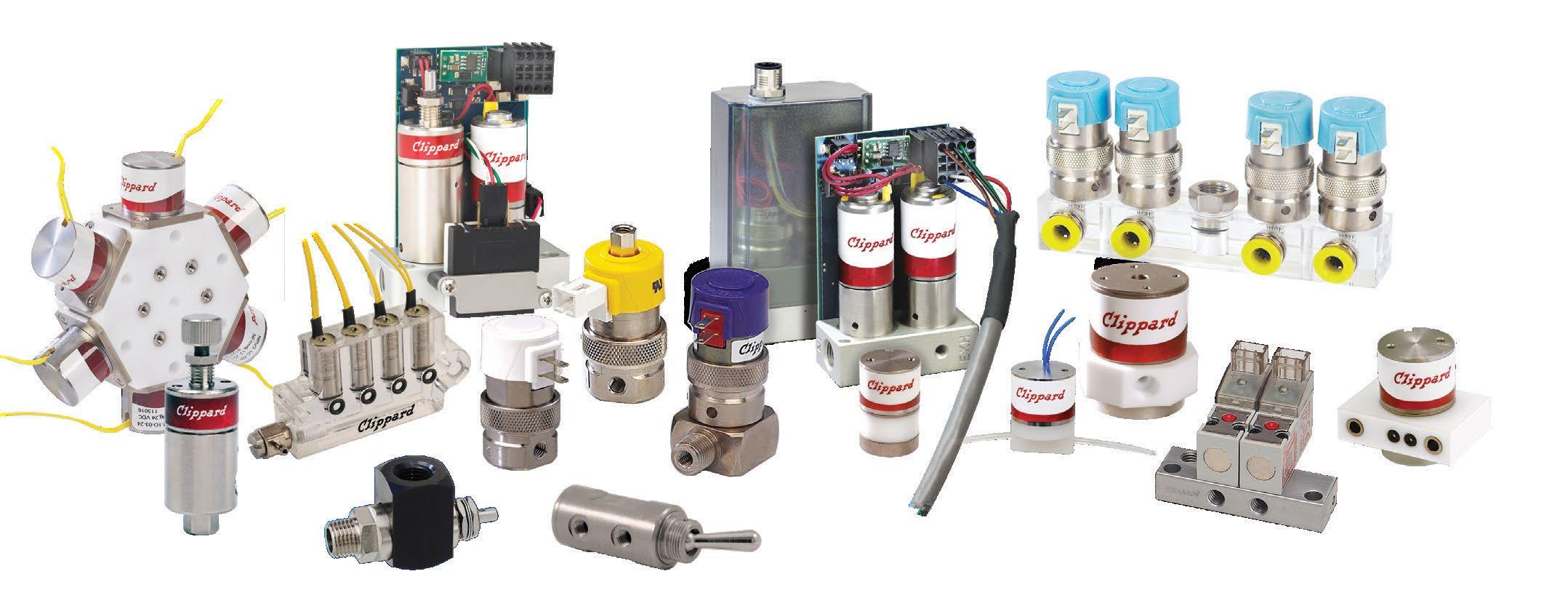
• Electronic Valves
• Proportional Valves
• Isolation Valves
• Pinch Valves
• Precision Regulators
• Toggle & Stem Valves
• Needle Valves
• Electronic Controllers
• Pneumatic Assemblies
• Special Manifold Designs
• Pneumatic Circuit Design
• Fittings, Hose & Tubing

» TEST YOUR SKILLS
03 Computing the Cost of CFM Leakage in a Compressed Air System Stay sharp with this monthly lesson from the IFPS's study guide.
12 Ensuring Optimal Performance & Longevity in Hydraulic Cylinders Hydraulic cylinder integrity starts with cleanliness, testing, and discipline.
14 Overcoming Engineering Challenges in High-Flow, High Pressure Proportional Valves Engineers overcome challenges to ensure hydraulic systems’ efficiency.
16 Achieving OEM Performance Standards in High-Pressure Piston Pump Restoration Strategies for meeting piston pump repair and restoration needs prove to be a success.
18 From Failure Mechanisms To Reconditioned Reliability in Heavy-Duty Applications
High-pressure hydraulic components serve as the backbone of applications.
» COVER STORY
20 Proportional Valve Amplifiers: Setup, Tuning, and Troubleshooting
A webinar as presented by Ken Dulinski, CFPAI, CFPJPP, CFPHS.
Publisher’s Note: The information provided in this publication is for informational purposes only. While all efforts have been taken to ensure the technical accuracy of the material enclosed, Fluid Power Journal is not responsible for the availability, accuracy, currency, or reliability of any information, statement, opinion, or advice contained in a third party’s material. Fluid Power Journal will not be liable for any loss or damage caused by reliance on information obtained in this publication.

Air leaks are costly because the compressor must be operated to replenish the loss. Experience tells us that most air systems leak at several connections and at a few components.
The question of how much air should be allowed to leak before the system is repaired varies by industry, the cost of isolating and fixing the leak, and the cost of shutting down the system to make repairs, if this is required. One source reports that when the loss exceeds 10% of the of the compressed air produced, the source of the leaks should be found and repaired.
The amount of air lost through a leak is computed as if the leak were passing air through an air line to the atmosphere without doing useful work. The cost equals the product of the volume, in cubic feet, times the cost to produce the air. That is: Air Leakage
$ = scfm × min × (kWh/scf) × ($/kWh)
Equation 8
NOTE: In the equation above, the unit(s) of time refers to the number of minutes being evaluated. If the cost is calculated for one full day (24 hours), the time would be calculated as 24 hours x 60 min/hour, or 1440 min. If we are evaluating the cost over a full 7 day week, we would multiply 1440 x 7 days to get 10080 minutes. From there we can figure the cost over any period of time in order to determine the value of fixing the leaks. •
See page 27 for the solution.

The organizing committee of the 2026 MAHA Fluid Power Conference (September 8-10, 2026) is excited to announce the preliminary program is now available online! This year, the conference will take place at Purdue University’s Stewart Center in West Lafayette, IN.
Anticipate an engaging event focused on fluid power and motion control technology, featuring insightful technical sessions from industry leaders and academia. Don't miss out! Register before August 15, 2026, to secure your spot and avoid higher registration fees.
Interested in participating in the conference expo or sponsoring the event? Email us at mahaav@ecn.purdue.edu for more information.
For additional details, visit the conference website: engineering.purdue.edu/Maha/conferences/2026/2026_MahaConference.
By Frank Langro, Director – Product Market Management, Pneumatic Automation, Festo North America

» DESPITE ONGOING CLAIMS about the decline of pneumatics in machine design, the technology remains widely used across major manufacturing industries. Its power density, compact size, and lightweight nature continue to make it a practical choice for many applications. With that in mind, the knowledge required to design and apply pneumatic systems effectively is often underdeveloped. Given its role in modern automation, a working knowledge of pneumatic systems is not optional. Machine designers must understand how to properly select, size, and apply these systems to achieve reliable performance. Why is this knowledge of pneumatics so critical? Improper selection and sizing of components can lead to poorly performing and inefficient equipment, longer machine commissioning, and a higher reliance on software to tune out the system’s physical flaws.
The challenge faced by the industry is where to find engineers with the training and skills in the design of pneumatic systems, as
this is not a common curriculum in most universities. While mechatronics programs have, fortunately, become more common at the university level, there is limited fluid power education. Industry organizations, such as the International Fluid Power Society (IFPS) and the National Fluid Power Association (NFPA), aim to correct this gap in education through their workforce development programs and partnering with select educational institutes. Vendors may also offer training targeted at the existing workforce. For instance, Festo’s Didactic Division offers a multitude of vendor-neutral industrial training. Topics include the basics of fluid power, PLC programming, and advanced topics like machine safety. Hands-on training is a vital component of this instruction as it gives the trainee firsthand visualization of system behavior. These organizations and companies can educate the workforce on the uses and design of fluid power systems; however, this occurs after these people have entered the workforce. What the industry truly needs is a way to educate future workers about fluid power and its uses and misuses.
Fortunately, I had the chance recently to witness the future leaders, innovators, and entrepreneurs at the FIRST Robotics Competition (FRC) at Long Island Regional. For those not familiar with FIRST, it is an acronym for Inspiration & Recognition of Science & Technology, and is one of the leading youth robotics communities. The FRC program is tailored to high school students, as they design and build robots to enter a competition in which the robot must perform multiple functions to accumulate points. The robots can employ a variety of
automation components. Depending on the game challenge, this can be a student’s first exposure to pneumatic technology.
As a longtime volunteer judge at this competition, I’ve had the fabulous opportunity to speak with the students about their robot designs, why they chose certain solutions, and what advantages some technologies have over others. Listening to the students speak about their findings and about pneumatics highlights how practical exposure to fluid power has a strong learning effect. By utilizing pneumatics, students learn through actual applications the considerations of force, speed, pressure loss, tubing length, and the use of flow controls and cushioning on a cylinder. Until you see the effect of improper cushioning on a cylinder and the resulting noise and vibration it causes, it can be difficult to understand the ramifications that this has on a system. Selecting the correct vacuum cup for the material that it will be picking up, by considering the porosity and surface of the item, is another skill that truly benefits from practical application, know-how, and learning by doing.
Being in the fluid power industry for over 30 years has certainly exposed me to what I consider the gap in knowledge for new entrants into the industry. To close that knowledge gap, the responsibility rests with us to become involved with industry organizations that support fluid power education, as well as programs like FIRST, that bring industry professionals in touch with students to expose them to engineering and fluid power. This will help drive change and close the knowledge gap we are currently faced with, taking the “new” out of pneumatics.
Innovative Designs & Publishing, Inc.
3245 Freemansburg Avenue, Palmer, PA 18045-7118
Tel: 800-730-5904 or 610-923-0380
Fax: 610-923-0390 • Email: Art@FluidPowerJournal.com www.FluidPowerJournal.com
Founders: Paul and Lisa Prass
Associate Publisher: Hannah Coursey
Editor: Lauren Schmeal
Technical Editor: Dan Helgerson, CFPAI/AJPP, CFPS, CFPECS, CFPSD, CFPMT, CFPCC
Senior Marketing Consultant: Bob McKinney
Graphic Designer: Nicholas Reeder Accounting: Leza Ovten
Circulation Manager: Josh Shoup
INTERNATIONAL FLUID POWER SOCIETY
1930 East Marlton Pike, Suite A-2, Cherry Hill, NJ 08003-2141
Tel: 856-424-8998 • Fax: 856-424-9248
Email: AskUs@ifps.org • Web: www.ifps.org
2026 BOARD OF DIRECTORS
President: Garrett Hoisington, CFPAI, CFPS, CFPMHM
Immediate Past President: Jeff Hodges, CFPAI/AJPP, CFPMHM - Altec Industries, Inc
First Vice President: Chauntelle Baughman, CFPHSOneHydraulics, Inc.
Treasurer: Elisabeth DeBenedetto, CCFPS, GS Global Resources
Vice President Education: Daniel Fernandes, CFPS, CFPECS, Hydra-Power Systems
Vice President Membership: Brian Wheeler, CFPAI/AJPP - The Boeing Company
Vice President Certification: Bruce Bowe, CFPAI/AJPP - Altec Industries, Inc.
Vice President Marketing: Bradlee Dittmer, CFPPS - IMI Precision Engineering DIRECTORS-AT-LARGE
Tyler Janecek, CFPHS - Engineering Systems, Inc
John Juhasz, CFPS - Kraft Fluid Systems
Stephen Blazer, CFPE- Altec Industries, Inc.
Brian Kenoyer, CFPS - Cemen Tech
Jeff Curlee, CFPS -Cross Mobile Hydraulics & Controls
Quest Duperron, CFPIHM, CFPCC - Coastal Hydraulics, Inc. Cary Boozer, CFPE - Motion Industries, Inc.
Steven Downey, CFPAI, CFPS - Hydraulex Deepak Kadamanahalli, CFPS - CNH Industrial Kyler
Craig Ridgeway, CFPHS - Bradbury Company
Alex Kummer, CFPE, - National Oilwell Varco
Wade Lowe, CFPS - Hydraquip Distribution, Inc. CHIEF EXECUTIVE OFFICER (EX-OFFICIO) Donna Pollander, ACA HONORARY DIRECTOR (EX-OFFICIO) Ernie Parker, Hydra Tech, Inc. CFPAI/AJPP
James O'Halek, CFPAI/AJPP, CFPMM, CFPMIP, CFPCCThe Boeing Company IFPS STAFF
Chief Executive Officer: Donna Pollander, ACA
Communications Coordinator: Stephanie Coleman
Director Training/Development: Bradley (BJ) Wagner, CFPAI/AJPP
Assistant Director: Jenna Mort
Certification Logistics Manager: Kyle Pollander Bookkeeper: Diane McMahon
Instructional Designer & Layout: Chalie Clair Fluid Power Journal (ISSN# 1073-7898) is the official publication of the International Fluid Power Society published monthly with four supplemental issues, including a Systems Integrator Directory, Off-Highway Suppliers Directory, Tech Directory, and Manufacturers Directory, by Innovative Designs & Publishing, Inc., 3245 Freemansburg Avenue, Palmer, PA 18045-7118. All Rights Reserved. Reproduction in whole or in part of any material in this publication is acceptable with credit. Publishers assume no liability for any information published. We reserve the right to accept or reject all advertising material and will not guarantee the return or safety of unsolicited art, photographs, or manuscripts.
» CREATING A CERTIFIED workforce starts with giving employees access to trusted training, easy-to-follow study materials, and industry-recognized certification opportunities that support real growth in the fluid power industry. Through IFPS programs, companies can help their teams strengthen technical knowledge, build confidence on the job, and develop the skills needed to troubleshoot, communicate, and perform more effectively in their roles.
IFPS also offers customized training options for groups before taking a certification test, helping teams prepare together with focused instruction that fits their needs. In addition, IFPS provides a wide range of study and training materials designed for both groups and individuals, making it easier for employees at all experience levels to prepare for certification and continue building their fluid power knowledge.
Investing in training and certification helps strengthen the organization as a whole. A team with IFPS credentials demonstrates a commitment to professionalism, safety, and technical excellence, while helping companies improve consistency, support employee development, and build a more knowledgeable workforce. For customers and industry partners, certification shows that a company values high standards and is dedicated to providing reliable, skilled, and informed service. Learn more at https://ifps.org/ prepare-for-a-certification-test-2.

EXPLORE IFPS BLOGS & FORUMS
» THE IFPS BLOGS and Forums give our community a place to continue learning, explore industry topics, and stay connected with others in the fluid power community. Recent blog topics such as “5 Things You Didn’t Know Use Hydraulics (Yes, Even That One)” and “Pascal’s Law: The Science Behind Hydraulic Superpowers” help make technical concepts more approachable while showing how fluid power is used in everyday equipment, systems, and real-world applications.
In addition to reading the latest blog posts, members and industry professionals are encouraged to join the IFPS Forums to ask questions, share insight, and participate in meaningful technical discussions. Whether you are preparing for certification, looking to expand your knowledge, or simply interested in learning more about fluid power, the Blogs and Forums provide valuable opportunities to stay informed, engaged, and connected. Join the conversation today!

CONNECTOR & CONDUCTOR
Zahra Al-azadi, The Boeing Company
Alicia Alaniz, The Boeing Company
Phillip Barker, The Boeing Company
Riley Cruz, The Boeing Company
Alexis Cutsforth, The Boeing Company
Cubi Decastro, The Boeing Company
Dutch Kiyota, The Boeing Company
William Krokhalev, The Boeing Company
Jason Painter, The Boeing Company
Alexander Rivera
Samuel Spagnoli, The Boeing Company
Jason Taylor, The Boeing Company
ELECTRONIC CONTROLS SPECIALIST
Samuel Clyde, Hydra-Power Systems
Wes Tatton
ENGINEER
Paul Vandervest, IFP Automation
Tammy Vandervest, IFP Automation
Thomas Yarick, Parker
HYDRAULIC SPECIALIST
Mohammed Al Mousa
Crystal Bower, Parker Hannifin
Joseph Capparelli, HydroAir
Kailey Carpenter, Sun Hydraulics
Charles Carrier, Hydraulex- Detroit
Steve Cater, Eastern Fluid Power
Ryan Clark, Hydradyne
Glen Comer, Engineered Sales
Michael Conley, Terrepower
Kyle Cunningham, DTS Fluid Power
Nick Dancz, Spencer Fluid Power
Brent Darling, Fluidtech
Yusong Ding, Eagle Hydraulic Inc.
Matt Douglas, HYDAC Technology Corporation
Adam Dupree, Motion Industries
Stepherson Eymard, HYDAC Technology Corporation
Jack Fryzel, Parker-Hannifin Corporation
Joshua Gant, Engineered Sales
Jared Gellner, HYDAC Technology Corporation
Joshua Gertsch, Spencer Fluid Power
CJ Gray, Hydraulex
Michael Grossmann, HYDAC Technology Corporation
Nazmul Hasan, NopStation
Keith Hightower, Terrepower
Shane Hoogewerf, HYDAC Technology Corporation
Charlie Houser, HYDAC Technology Corporation
Dillon Hude, Trident Maritime Systems
Danielle Jasinski, HYDAC Technology Corporation
Larry Johnson, Terrepower
Clayton Kawasaki, Terrepower
Lily Klein, Parker Hannifin
Grant Mccarter, Parker Hannifin
Stanley Miller, Terrepower-Detroit
Idris Muhammad, Parker Hannifin
Connor O'Toole, Parker Hannifin
Parmesh Pal, Maclean Engineering
Cory Patterson, Parker
Shivam Prakash, Terrepower
Hugo Rios, Terrepower
Josiah Saari, HYDAC Technology Corporation
Chris Schumpert, Hydraulex
Coleman Scroggs, SunSource
Robert Shannon, Spencer Fluid Power
Lakhwinder Singh, HYDAC Technology Corporation
Joseph Strack, HYDAC Technology Corporation
William Taylor, NOV
Wayne Vilchuck, HYDAC Technology Corporation
Olivia Vukovic, Parker Hannifin
Jackson Wallis, Parker Hannifin
Henry Wasoski, Parker Hannifin
Owen Watson, Parker Hannifin
George Wehmann, HYDAC Technology Corporation
Randall Wildner, Hydraulex
Randy Wildner, Hydraulex
INDUSTRIAL HYDRAULIC MECHANIC
Craig Durham, Magna
Jared Kennedy
Craig Nelson, Eagle Bend MFG
Brandon Paradise, Hydradyne LLC.
Parker Shelton, Hydradyne LLC.
Craig Stagnolia, Magna
INDUSTRIAL HYDRAULIC TECHNICIAN
Justin Adams, Hyflodraulic LTD.
Ashton Morgan, Hyflodraulic LTD.
Keith Pretty, Hyflodraulic LTD.
Kenneth Soper, Hyflodraulic LTD.
Wes Tatton

» DID YOU KNOW IFPS offers sponsorship opportunities that support education, certification, and workforce development in the fluid power industry? The IFPS Annual Sponsorship Program includes multiple sponsorship levels designed to provide recognition, engagement opportunities, and sponsor benefits for organizations committed to advancing the industry.
Sponsorships are a meaningful way for companies to align their brand with professional development while connecting with fluid power professionals, students, educators, and industry leaders. In addition to annual sponsorship opportunities, limited sponsorships are available throughout the year for specific projects, giving companies additional ways to support IFPS initiatives, promote industry education, and stay visible within a highly targeted fluid power audience. Visit https://www.ifps.org/ifps-sponsorship-opportunities to learn more.
MOBILE HYDRAULIC MECHANIC
Gilberto Armas Perez, Florida Power and Light
John Bailey, Florida Power and Light
Lukasz Dalmata, Florida Power and Light
Brian Aguirre, Altec Industries, Inc.
Nathan Allen, Altec Industries, Inc.
Alvaro Bailon, Altec Industries, Inc.
Austin Bohannon, Altec Industries, Inc.
Francisco Bravo, Altec Industries, Inc.
Chris Brill, ComEd
Buddy Byrd, Oklahoma Electric Cooperative
Gabriel Carrasquillo, ComEd
Kevin Castillo, Florida Power and Light
Joseph Clark, Florida Power and Light
Matthew Cloud, Consolidated Truck
Miguel Garcia, Altec Industries, Inc.
Miguel Garcia, ComEd
Samuel Garcia, Altec Industries, Inc.
Jared Hall, Altec Industries, Inc.
Jeremiah Hopson, Altec Industries, Inc.
Mark Hughes, Altec Industries, Inc.
Stetson Jensen, Altec Industries, Inc.
Carl Lee, The Boeing Company
James Locke, ComEd
Sebastian Luna, Altec Industries, Inc.
Connor Mule
Daniel Myron, Altec Industries, Inc.
Alberto Pena, Altec Industries, Inc.
Jordon Peterson, ComEd
Cameron Rowe, Altec Industries, Inc.
Connor Schmitz, Brink Constructors
Christopher Scott, Altec Industries, Inc.
Garrett Sheppard, Altec Industries, Inc.
Michal Smal, ComEd
Joseph Smith, Altec Industries, Inc.
Curtis Stephens, Serco
Earl Suffel, Altec Industries, Inc.
Richard Summerton, Altec Industries, Inc.
Fred Taillon, ComEd
Feliciano Vargas, ComEd
Dominic Waudby, Altec Industries, Inc.
Kyle Wines, Oklahoma Electric Cooperative
MOBILE HYDRAULIC TECHNICIAN
Bradford Mailloux, The Boeing Company
PNEUMATIC MECHANIC
Destiny Cruz, The Boeing Company
Hank Santiago
PNEUMATIC SPECIALIST
Jonathon Anderson
Fatima Ayoubi, IMI
Robert Crowder, Altec Industries, Inc.
Zachary Dehmer
Tyler Goodwin, Hydraulic Supply and Service Company
Ted Grozio, IMI
Caleb Happach, IMI
Tom Hoover, IMI
William Kapherr, Altec Industries, Inc.
Caden Kemp, IMI
Connor Lindahl
Trevor McNamara
Taylor Nethery, IMI
Daniel Petrou, IMI
David Schiller
Stephen Thornton
Adam Tsoufiou, IMI
Jae Yun, IMI
SPECIALIST
Jonathon Anderson
Zachary Dehmer
Jack Fryzel, Parker-Hannifin Corporation
Tyler Goodwin, Hydraulic Supply and Service Company
William Kapherr, Altec Industries, Inc.
Grant McCarter, Parker Hannifin
Trevor McNamara
Idris Muhammad, Parker Hannifin
Connor O'Toole, Parker Hannifin
Jackson Wallis, Parker Hannifin
SUPPORT ASSOCIATE
Kyle Anderson, FluiDyne Fluid Power
Elijah Bakos, Kraft Mobile Systems
Josh Bennett, FluiDyne Fluid Power
Charles Chalk, FluiDyne Fluid Power
Tyran Christian, FluiDyne Fluid Power
Katherine Clark, Hydradyne
Meghan Hollis, Engineered Sales
Brandon Holt, Supreme Integrated Technology
Ann McGuffie, FluiDyne Fluid Power
Andrew Metz, FluiDyne Fluid Power
Dax Middlebrooks, Evolution Motion Solutions
Tiffany Myers, FluiDyne Fluid Power
Donovan Reed, FluiDyne Fluid Power
Torey Robertson, FluiDyne Fluid Power
Matthew Sparks, FluiDyne Fluid Power
Ty Weiss, IFP Motion Solutions Inc.
Individuals wishing to take any IFPS written certification tests can select from convenient locations across the United States and Canada. IFPS is able to offer these locations through its affiliation with the Consortium of College Testing Centers provided by National College Testing Association. Contact Kyle Pollander at Kpollander@ifps.org if you do not see a location near you. Every effort will be made to accommodate your needs.
Alabama Auburn, AL Birmingham, AL Calera, AL Decatur, AL Huntsville, AL Jacksonville, AL Mobile, AL Montgomery, AL Normal, AL Tuscaloosa, AL
Alaska Anchorage, AK Fairbanks, AK
Arizona Flagstaff, AZ Glendale, AZ Mesa, AZ Phoenix, AZ Prescott, AZ Scottsdale, AZ
Sierra Vista, AZ Tempe, AZ Thatcher, AZ Tucson, AZ Yuma, AZ
Arkansas Bentonville, AR Hot Springs, AR Little Rock, AR
JULY 2026
Tuesday 7/7 • Thursday 7/23
AUGUST 2026
Tuesday 8/11 • Thursday 8/27
SEPTEMBER 2026
Tuesday 9/1 • Thursday 9/24
OCTOBER 2026
Tuesday 10/6 • Thursday 10/22
California Aptos, CA Arcata, CA Bakersfield, CA Dixon, CA Encinitas, CA Fresno, CA Irvine, CA
Marysville, CA Riverside, CA Salinas, CA San Diego, CA San Jose, CA San Luis Obispo, CA Santa Ana, CA Santa Maria, CA Santa Rosa, CA Tustin, CA Yucaipa, CA Colorado Aurora, CO Boulder, CO Springs, CO Denver, CO
Durango, CO Ft. Collins, CO Greeley, CO Lakewood, CO Littleton, CO Pueblo, CO
Georgia
Albany, GA
Athens, GA
Atlanta, GA
Carrollton, GA
Columbus, GA
Dahlonega, GA
Dublin, GA
Dunwoody, GA
Forest Park, GA
Lawrenceville, GA
Morrow, GA
Oakwood, GA
Savannah, GA
Statesboro, GA
Tifton, GA
Valdosta, GA
Hawaii Laie, HI
Idaho Boise, ID
Coeur d ‘Alene, ID
Idaho Falls, ID
Lewiston, ID
Moscow, ID
Nampa, ID
Rexburg, ID
Twin Falls, ID
Illinois
Carbondale, IL
Carterville, IL
Champaign, IL
Decatur, IL
Edwardsville, IL
Glen Ellyn, IL
Joliet, IL
Malta, IL
Normal, IL
Peoria, IL
Schaumburg, IL
Springfield, IL
University Park, IL
Indiana
Bloomington, IN
Columbus, IN
Evansville, IN
Fort Wayne, IN
Gary, IN
Indianapolis, IN
Kokomo, IN
Lafayette, IN
Lawrenceburg, IN
Madison, IN
Muncie, IN
New Albany, IN
Richmond, IN
Sellersburg, IN
South Bend, IN
Terre Haute, IN
Iowa Ames, IA
Maryland
Arnold, MD
Bel Air, MD
College Park, MD
Frederick, MD
Hagerstown, MD
La Plata, MD
Westminster, MD
Woodlawn, MD
Wye Mills, MD
Massachusetts
Boston, MA
Bridgewater, MA
Danvers, MA
Haverhill, MA
Holyoke, MA
Shrewsbury, MA
Michigan
Ann Arbor, MI
Big Rapids, MI
Chesterfield, MI
Dearborn, MI
Dowagiac, MI
East Lansing, MI
Flint, MI
Grand Rapids, MI
Kalamazoo, MI
Lansing, MI
Livonia, MI
Mount Pleasant, MI
Sault Ste. Marie, MI
Troy, MI
University Center, MI
Warren, MI
Minnesota
Alexandria, MN
Brooklyn Park, MN
Duluth, MN
Eden Prairie, MN
Granite Falls, MN
Mankato, MN
Mississippi
Goodman, MS
Jackson, MS
Mississippi State, MS
Raymond, MS
University, MS
Missouri
Berkley, MO
Cape Girardeau, MO
Columbia, MO
Cottleville, MO
Joplin, MO
Kansas City, MO
Kirksville, MO
Park Hills, MO
Poplar Bluff, MO
Rolla, MO
Sedalia, MO
Springfield, MO
St. Joseph, MO
New Mexico Albuquerque, NM
Clovis, NM
Farmington, NM
Portales, NM
Santa Fe, NM
New York
Alfred, NY
Brooklyn, NY
Buffalo, NY
Garden City, NY
New York, NY
Rochester, NY
Syracuse, NY
North Carolina Apex, NC
Asheville, NC
Boone, NC
Charlotte, NC
China Grove, NC
Durham, NC
Fayetteville, NC
Greenville, NC
Jamestown, NC
Misenheimer, NC
Mount Airy, NC
Pembroke, NC
Raleigh, NC
Wilmington, NC
North Dakota
Bismarck, ND
Ohio Akron, OH
Cincinnati, OH
Cleveland, OH
Columbus, OH
Fairfield, OH
Findlay, OH
Kirtland, OH
Lima, OH
Maumee, OH
Newark, OH
North Royalton, OH
Rio Grande, OH
Toledo, OH
Warren, OH
Youngstown, OH
Oklahoma Altus, OK
Bethany, OK
Edmond, OK
Norman, OK
Oklahoma City, OK
Tonkawa, OK
Tulsa, OK
Oregon Bend, OR Coos Bay, OR Eugene, OR
Gresham, OR
Tennessee Blountville, TN
Clarksville, TN
Collegedale, TN
Gallatin, TN
Johnson City, TN
Knoxville, TN
Memphis, TN
Morristown, TN
Murfreesboro, TN
Nashville, TN
Texas
Abilene, TX
Arlington, TX
Austin, TX
Beaumont, TX
Brownsville, TX
Commerce, TX
Corpus Christi, TX
Dallas, TX
Denison, TX
El Paso, TX
Houston, TX
Huntsville, TX
Laredo, TX
Lubbock, TX
Lufkin, TX
Mesquite, TX
San Antonio, TX
Victoria, TX
Waxahachie, TX
Weatherford, TX
Wichita Falls, TX
Utah Cedar City, UT
Kaysville, UT
Logan, UT
Ogden, UT
Orem, UT
Salt Lake City, UT
Virginia
Daleville, VA
Fredericksburg, VA
Lynchburg, VA
Manassas, VA
Norfolk, VA
Roanoke, VA
Salem, VA
Staunton, VA
Suffolk, VA
Virginia Beach, VA
Wytheville, VA
Washington Auburn, WA
Bellingham, WA
Bremerton, WA
Ellensburg, WA
Ephrata, WA
Olympia, WA
Pasco, WA
Rockingham, WA
Seattle, WA
British Columbia Abbotsford, BC
Burnaby, BC
Castlegar, BC
Delta, BC
Kamloops, BC
Nanaimo, BC
Prince George, BC Richmond, BC Surrey, BC
Vancouver, BC
Victoria, BC
Manitoba Brandon, MB
Winnipeg, MB
New Brunswick Bathurst, NB Moncton, NB
Newfoundland and Labrador St. John’s, NL
Nova Scotia Halifax, NS
Ontario
Brockville, ON Hamilton, ON London, ON Milton, ON Mississauga, ON Niagara-on-the-Lake, ON
North Bay, ON North York, ON Ottawa, ON Toronto, ON Welland, ON Windsor, ON
Quebec
Côte Saint-Luc, QB Montreal, QB
Saskatchewan Melfort, SK
Moose Jaw, SK Nipawin, SK
Prince Albert, SK Saskatoon, SK
Yukon Territory Whitehorse, YU
UNITED KINGDOM
Elgin, UK
GHAZNI
Kingdom of Bahrain, GHA Thomasville, GHA
JOB PERFORMANCE TEST LOCATIONS
Arizona California Colorado Florida Georgia
Maine
Michigan Minnesota
Montana New Jersey Nova Scotia Pennsylvania Texas Washington Wyoming Western Australia
Delaware Dover, DE Georgetown, DE Newark, DE
Florida
Avon Park, FL Boca Raton, FL Cocoa, FL Davie, FL Daytona Beach, FL
Fort Pierce, FL
Ft. Myers, FL Gainesville, FL Jacksonville, FL
Miami Gardens, FL Milton, FL
New Port Richey, FL Ocala, FL Orlando, FL
Panama City, FL
Pembroke Pines, FL Pensacola, FL
Plant City, FL Riviera Beach, FL Sanford, FL Tallahassee, FL Tampa, FL
West Palm Beach, FL
Wildwood, FL Winter Haven, FL
Cedar Rapids, IA
Iowa City, IA
Ottumwa, IA
Sioux City, IA
Waterloo, IA
Kansas
Kansas City, KS
Lawrence, KS
Manhattan, KS
Wichita, KS
Kentucky
Ashland, KY
Bowling Green, KY
Erlanger, KY
Highland Heights, KY
Louisville, KY
Morehead, KY
Louisiana
Bossier City, LA
Lafayette, LA
Monroe, LA
Natchitoches, LA
New Orleans, LA
Shreveport, LA
Thibodaux, LA
St. Louis, MO
Warrensburg, MO
Montana
Bozeman, MT
Missoula, MT
Nebraska
Lincoln, NE
North Platte, NE
Omaha, NE
Nevada
Henderson, NV
Las Vegas, NV
North Las Vegas, NV
Winnemucca, NV
New Jersey
Branchburg, NJ
Cherry Hill, NJ
Lincroft, NJ
Sewell, NJ
Toms River, NJ
West Windsor, NJ
Klamath Falls, OR
Medford, OR
Oregon City, OR
Portland, OR
White City, OR
Pennsylvania Bloomsburg, PA Blue Bell, PA
Gettysburg, PA
Harrisburg, PA
Lancaster, PA
Newtown, PA Philadelphia, PA Pittsburgh, PA
Wilkes-Barre, PA York, PA
South Carolina
Beaufort, SC Charleston, SC Columbia, SC
Conway, SC
Graniteville, SC
Greenville, SC Greenwood, SC Orangeburg, SC
Rock Hill, SC
Spartanburg, SC
Shoreline, WA
Spokane, WA
West Virginia
Ona, WV
Wisconsin
La Crosse, WI
Milwaukee, WI
Mukwonago, WI
Wyoming
Casper, WY
Laramie, WY
Torrington, WY
CANADA
Alberta
Calgary, AB
Edmonton, AB
Fort McMurray, AB
Lethbridge, AB
Lloydminster, AB Olds, AB
Red Deer, AB
EGYPT Cairo, EG
JORDAN Amman, JOR
NEW ZEALAND Taradale, NZ
CFPAI
Certified Fluid Power Accredited Instructor
CFPAJPP
Certified Fluid Power Authorized Job Performance Proctor
CFPAJPPCC
Certified Fluid Power Authorized Job Performance Proctor Connector & Conductor
CFPE
Certified Fluid Power Engineer
CFPS
Certified Fluid Power Specialist (Must Obtain CFPHS & CFPPS)
CFPHS
Certified Fluid Power Hydraulic Specialist
CFPPS
Certified Fluid Power Pneumatic Specialist
CFPECS
Certified Fluid Power
Electronic Controls Specialist
CFPMT
Certified Fluid Power Master Technician (Must Obtain CFPIHT, CFPMHT, & CFPPT)
CFPIHT
Certified Fluid Power
Industrial Hydraulic Technician
CFPMHT
Certified Fluid Power
Mobile Hydraulic Technician
CFPPT
Certified Fluid Power Pneumatic Technician
CFPMM
Certified Fluid Power Master Mechanic (Must Obtain CFPIHM, CFPMHM, & CFPPM)
CFPIHM
Certified Fluid Power
Industrial Hydraulic Mechanic
CFPMHM
Certified Fluid Power
Mobile Hydraulic Mechanic
CFPPM
Certified Fluid Power
Pneumatic Mechanic
CFPMIH
Certified Fluid Power
Master of Industrial Hydraulics
(Must Obtain CFPIHM, CFPIHT, & CFPCC)
CFPMMH
Certified Fluid Power
Master of Mobile Hydraulics (Must Obtain CFPMHM, CFPMHT, & CFPCC)
CFPMIP
Certified Fluid Power
Master of Industrial Pneumatics (Must Obtain CFPPM, CFPPT, & CFPCC)
CFPCC
Certified Fluid Power
Connector & Conductor
CFPSD
Fluid Power System Designer
CFPSA
Certified Fluid Power Support Associate
IFPS offers onsite review training for small groups of at least 10 persons. An IFPS accredited instructor visits your company to conduct the review. Contact kpollander@ifps.org for details of the scheduled onsite reviews listed below.
HYDRAULIC SPECIALIST
For custom IFPS training inquiries, please contact Bj Wagner (bwagner@ifps.org)
ELECTRONIC CONTROLS SPECIALIST
For custom IFPS training inquiries, please contact Bj Wagner (bwagner@ifps.org).
PNEUMATIC SPECIALIST
For custom IFPS training inquiries, please contact Bj Wagner (bwagner@ifps.org)
CONNECTOR & CONDUCTOR
For custom IFPS training inquiries, please contact Bj Wagner (bwagner@ifps.org).
MOBILE HYDRAULIC MECHANIC
For custom training IFPS inquiries, please contact Bj Wagner (bwagner@ifps.org)
Online Mobile Hydraulic Mechanic certification review for written test is offered through CFC Industrial Training. This course surveys the MHM Study Manual (6.5 hours) and every outcome to prepare you for the written test. Members may e-mail for a 20% coupon code off the list price. Test fees are not included.
INDUSTRIAL HYDRAULIC MECHANIC
For custom IFPS training inquiries, please contact Bj Wagner (bwagner@ifps.org).
INDUSTRIAL HYDRAULIC TECHNICIAN
For custom IFPS training inquiries, please contact Bj Wagner (bwagner@ifps.org).
» For dates, call CFC Industrial Training at (513) 874-3225 or visit www.cfcindustrialtraining.com.
MOBILE HYDRAULIC TECHNICIAN
For custom IFPS training inquiries, please contact Bj Wagner (bwagner@ifps.org).
PNEUMATIC TECHNICIAN & PNEUMATIC MECHANIC
For custom IFPS training inquiries, please contact Bj Wagner (bwagner@ifps.org).
» For dates, call CFC Industrial Training at (513) 874-3225 or visit www.cfcindustrialtraining.com.
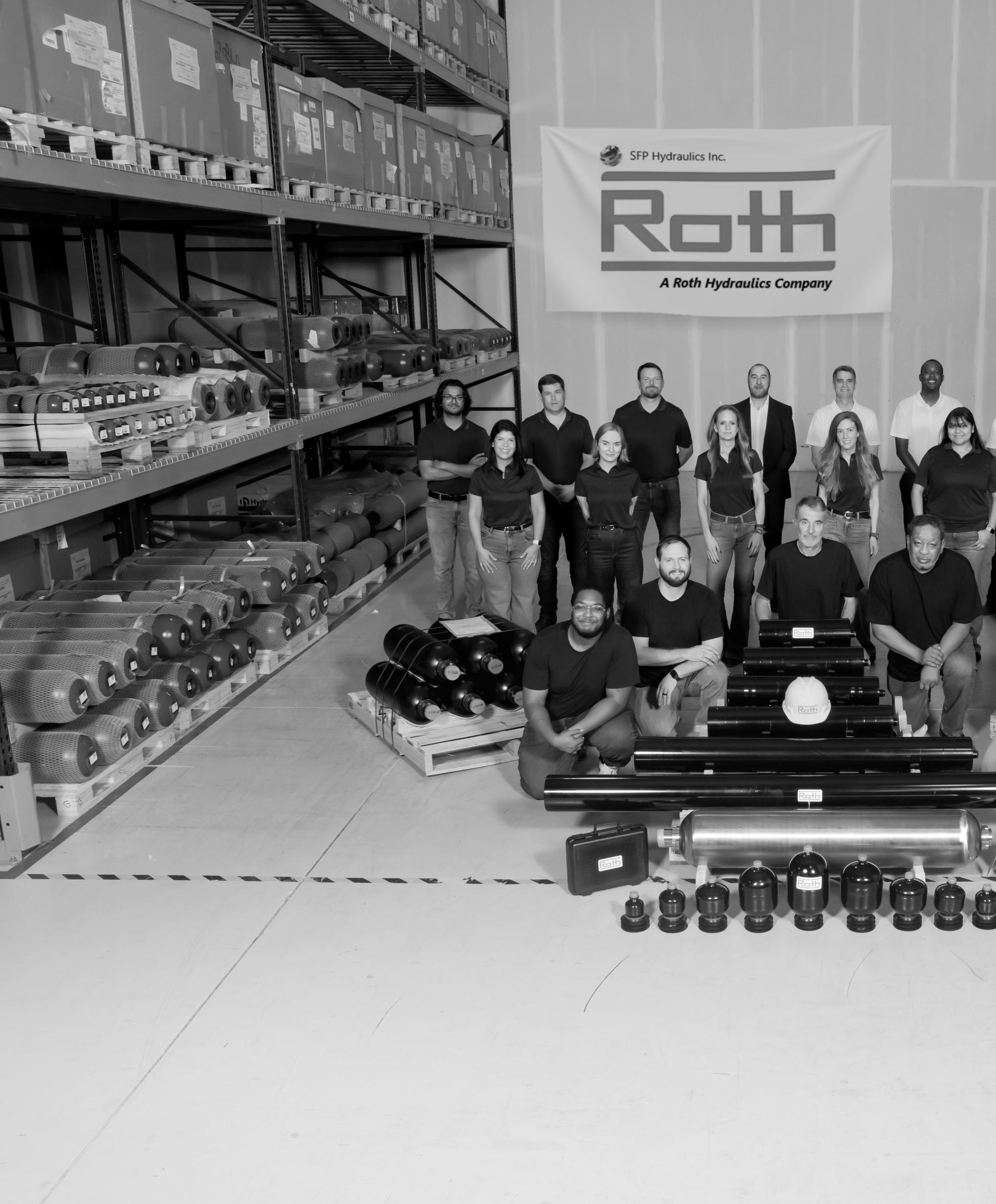
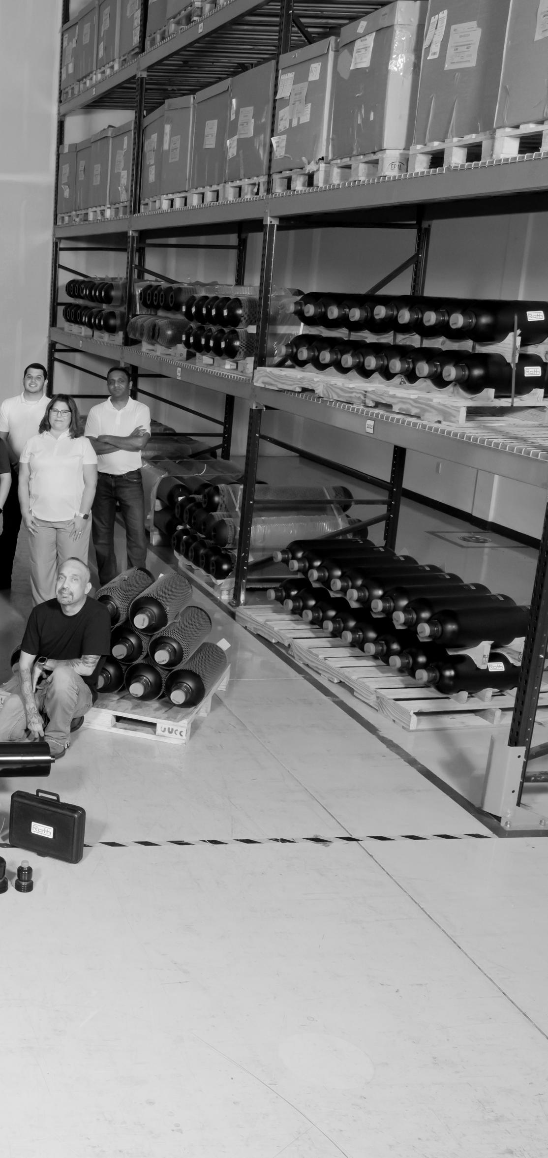
In 2014, amid an oil crisis and economic uncertainty, a small, self-funded hydraulic accumulator specialist set up shop in Houston’s Energy Corridor. SFP Hydraulics Inc. was built on deep technical expertise, a relentless focus on quality, and the kind of customer relationships that only come from delivering when it matters. Through Covid, oil price collapses, and volatile markets, SFP didn’t just survive — it earned a hard-won reputation as a trusted partner to some of the most demanding industries in the world.
In 2024, that reputation caught the attention of Roth — a German family business founded in 1947. The Roth world composes technologies for solutions full of energy, and today, is one of the most respected names in global hydraulics. SFP Hydraulics was acquired as Roth Hydraulics North American home.
Here’s what that means in plain terms: SFP Hydraulics Inc. is still here. The same products. The same people. The same commitment to getting it right. What’s changed is everything behind us — a world-class parent, a vastly expanded catalog, and the financial strength of a global group that has been building exceptional hydraulic solutions for nearly 80 years.
The Roth catalog doesn’t replace what SFP does — it complements it perfectly. Where SFP has built deep accumulator expertise, Roth brings global engineering strength across Mobile Hydraulics, Heavy Industry, and Railway Systems. Together, we can now offer customers a broader, stronger, more capable solution — without losing the responsiveness and personal service that built SFP’s reputation in the first place.
The Next Chapter
Leading SFP’s next chapter is Robin Hodgson, General Manager & President — a 24-year veteran of the US market with a proven track record of growing industrial businesses from startup to serious scale. Having built his career with German-owned companies before making the United States his home, Robin brings a rare combination of European engineering discipline and American commercial energy.
Robin is the first to acknowledge that the opportunity in front of him exists because of the foundation laid before him — and because of the extraordinary support now behind him. Backed by a team of 18 and the full weight of the Roth global network, the ambition is clear: diversify beyond oil and gas into aerospace, marine, hydro power, mining, and energy technology, and build SFP — under the Roth banner — into the accumulator partner of choice across North America.
“Ten years of groundwork. A world-class partner. A team that’s just getting warmed up. Performance you can count on — that’s not a tagline. That’s a promise.”
P: +1 281-347-8080 | E: info@sfphyd.com | W: sfphyd.com
Why hydrostatic testing, seal quality, contamination control, and preventive maintenance remain the foundation of reliable cylinder performance.
Hydraulic cylinders are among the most important components in industrial machinery, quietly converting fluid power into the force and motion that move excavators, presses, aircraft systems, farm equipment, and mining machines. Their work is often taken for granted until something goes wrong, e.g., a leak, a loss of pressure, or a failure that stops production and sends maintenance teams scrambling. Cylinder performance is shaped long before the cylinder reaches service, and it is preserved only when testing, cleanliness, sealing, storage, and maintenance are treated as part of a single system rather than as separate tasks.
The challenge is straightforward: hydraulic cylinders are expected to perform under extreme pressure, in contaminated environments, and often for long service intervals without interruption. That expectation makes quality control essential. Failures rarely happen for a single reason. Instead, they usually begin with small issues, including dirty fluid, a weak seal, poor storage, or a skipped inspection. These
concerns grow into major problems over time. The best cylinder programs are designed to stop that chain before it starts.
Hydrostatic testing remains one of the most important tools for verifying cylinder integrity. By pressurizing a cylinder beyond its normal operating range, manufacturers and maintenance teams can expose weaknesses that would otherwise remain hidden until the cylinder is in the field. The purpose is not simply to prove that a cylinder “works,” but to confirm that it can withstand demanding conditions without leakage, deformation, or structural failure.
In practice, hydrostatic testing is a disciplined process. The cylinder is mounted securely, filled with incompressible fluid, and gradually brought up to a pressure well above its operating level. Engineers then watch for leaks, visible distortion, and seal problems. If a cylinder cannot pass the test, it is repaired or reinforced before it ever reaches the customer. Standards such as ISO 10100 and SAE J1336 help define how these tests are performed and why they matter. For users, hydrostatic testing offers something more valuable than a pass-fail result. It establishes confidence. A cylinder that has already proven
its ability to endure extreme pressure is far less likely to surprise an operator later with premature failure.
If testing proves strength, filtration preserves it. Contamination is one of the leading causes of hydraulic failure, and cylinders are especially vulnerable because abrasive particles attack seals, surfaces, and internal components over time. Even small amounts of dirt or debris can create wear that eventually shows up as leakage, pressure loss, or rough motion.
That is why fluid cleanliness is not an afterthought. Clean oil protects seals and pistons, reduces wear, and improves the overall efficiency of the system. Many manufacturers now treat filtration as part of the product itself, not just part of the machine. Using highly clean oil during testing and service reduces the chance that a cylinder will begin its life already exposed to damaging particles.
International cleanliness standards such as ISO 4406 give users a common language for measuring contamination, while offline filtration and kidney-loop systems help keep fluid within acceptable limits. In high-performance applications, clean oil is not a luxury. It is one of the simplest and most effective ways to extend service life.
Cylinder seals rarely get attention until they fail, but they are central to performance. Seals hold pressure, keep fluid where it belongs, and prevent outside contamination from entering the system. When seal quality is poor, the consequences are immediate: leakage, reduced efficiency, heat buildup, and more frequent maintenance.
Material choice matters. High-quality seals made from compatible compounds such as Viton, PTFE, or NBR can better withstand pressure, temperature, and chemical exposure. Low-friction designs also reduce wear on rods and pistons. Just as important are dust wipers and rod seals that keep debris from entering the cylinder in the first place.
Seal selection should always reflect the application. A cylinder working in a dusty mining environment faces different risks than one operating in a controlled industrial setting. The best sealing systems are not just durable; they are matched to the conditions they will face.
A cylinder can be built well, tested thoroughly, and filled with clean fluid, and still fail early if it is stored or maintained poorly. Long-term storage can dry out seals, expose surfaces to corrosion, and create problems before the cylinder is even installed. Protective oil films, sealed storage, and periodic rotation help preserve seal integrity and prevent flat spots or deformation.
Preventive maintenance plays the same role once the cylinder is in service. Regular oil analysis, pressure checks, visual inspections, and water testing can reveal early warning signs before they lead to costly failures. Tools such as Karl Fischer testing and contamination monitoring help maintenance teams catch moisture and wear that are otherwise invisible. This kind of discipline pays off because cylinder failures are rarely cheap. They can damage connected equipment, halt production, and create cascading problems throughout a system. Maintenance is not just about keeping cylinders alive; it is about protecting the machine around them.
Although electronic controls garner industry attention, conventional hydraulic valves still have an important place in fluid power. These mechanically or manually operated valves remain
valuable because they are rugged, reliable, and able to function without electricity. In remote, hazardous, or power-sensitive environments, that simplicity is a major advantage.
Directional control valves, pressure control valves, flow control valves, and check valves continue to support heavy-duty machinery across industrial, mobile, and mining applications. Their broad tolerance for contamination also makes them practical where ultra-clean conditions are difficult to maintain. That said, even conventional valving benefits from proper filtration, compatible materials, and routine inspection.
the lesSon is familiar: reliability is not acCidental. It comes from matching the right components to the right environment and supporting them with the right maintenance habits.
The most reliable hydraulic cylinders are rarely the result of one breakthrough. They are the product of several good decisions made consistently: testing at the right pressure, keeping fluid clean, selecting seals carefully, storing equipment properly, and maintaining it before problems escalate. Conventional valving follows the same logic. Simplicity and ruggedness only last when they are supported by sound engineering and disciplined care.
For hydraulic users, the takeaway is clear. Cylinder integrity is not a single event; it is a lifecycle strategy. The systems that perform best are the ones that are built, tested, operated, and maintained with the same standard of care from beginning to end. •
www. coxreels .com
Challenges
By Bill Keller, Engineering Manager, Bailey International

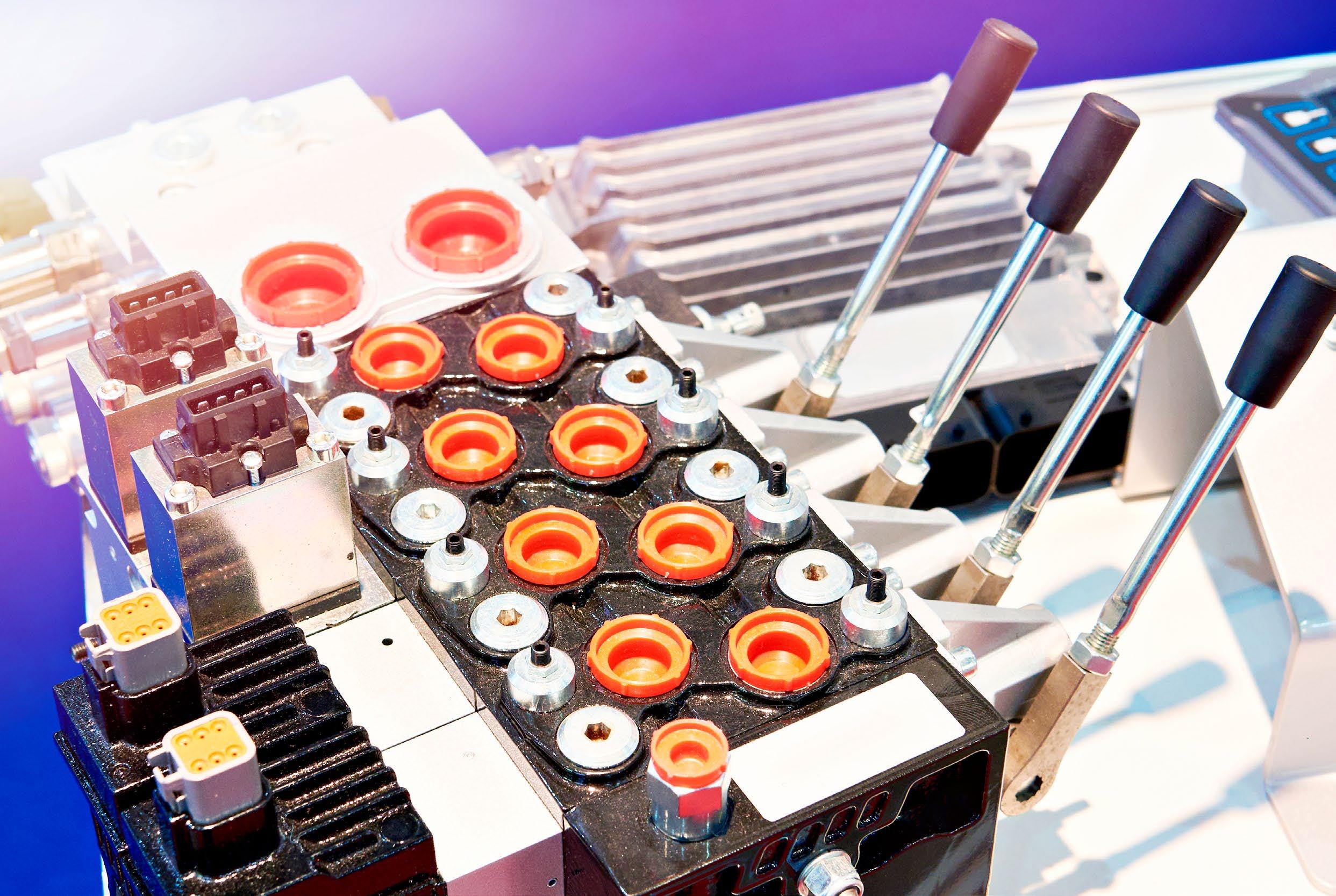
While standard directional valves provide simple open-and-close functionality, modern applications require the nuanced, throttled control that only proportional valves can deliver. Designing and integrating proportional valves for highflow, high-pressure environments presents a unique set of engineering hurdles. To maintain production schedules, reduce costs, and ensure long-term product reliability, OEMs must address critical challenges surrounding flow stability, heat management, hysteresis, leak paths, and system packaging.
Here is a look at how to navigate these obstacles and ensure your hydraulic systems operate efficiently and precisely.
Unlike traditional switching valves, proportional valves adopt infinite intermediate positions. This continuous change of state requires an electromagnetic actuation system that balances forces against return springs and hydraulic pressures. Maintaining precise and consistent flow rates across varying loads is essential.
A critical tool for achieving flow stability is the application of a dither signal, a rapid, small-amplitude fluctuation in the electrical current. Dither keeps the valve spool in constant micro-motion, preventing static friction from hanging up the valve. However, applying the incorrect dither frequency can cause severe system instability. To optimize performance, engineers should adhere to specific frequency ranges based on the valve type:
• Flow and Directional Control Valves: Utilize a dither frequency of 70 to 250 Hz.
• Proportional Pressure Control Valves: Utilize a higher frequency of 200 to 300 Hz.
• Poppet-Style Valves: Strictly avoid dither frequencies between 15 and 50 Hz. Matching the natural frequency of the poppet in this range will induce severe instability and destructive chattering.
In high-pressure hydraulic systems, heat is generated by fluid friction, and electromagnetic coils actuate the valves. Since valve position is directly related to the applied current rather than voltage, temperature fluctuations present a significant control challenge. As the coil heats up, its electrical resistance increases, which can degrade valve position accuracy and resolution if left unmanaged.
To ensure reliable performance in high ambient temperatures or continuous-duty applications, current limits must be strictly
managed. For example, it is best practice to limit the maximum current (I-Max) to 1.0 amps for 08-size valves and 1.2 amps for 10-size valves. Failing to account for this thermal resistance can result in a loss of voltage overhead, preventing the system from utilizing the full operational range of the valve.
Hysteresis is the difference in valve response when an input signal is increasing versus when it is decreasing, and it directly impacts the accuracy of a machine. In heavyduty OEM equipment, excessive hysteresis leads to unpredictable actuator movements and reduced operational efficiency. Addressing hysteresis requires a dual approach:
• Electrical Control: As noted, appropriately tuned dither frequencies reduce actuator friction, allowing the spool to respond instantly to changes in the command signal.
• Mechanical Precision: High-quality manufacturing is non-negotiable. Low hysteresis requires precision-machined armatures, specialized low-friction materials, and exact tolerances. Utilizing components manufactured with micrometer-level precision ensures smooth spool operation and reliable, repeatable performance.
High system pressures naturally seek out the path of least resistance. Preventing internal and external leakage is paramount to maintaining system efficiency, protecting the environment, and ensuring the safety of operators. In proportional valve design, sealing technology must be robust enough to
handle high-pressure spikes without degrading the smooth shifting of the spool. Utilizing specialized poppet designs can provide virtually leak-free operation where load-holding is required, while precision-honed spools and sleeves minimize internal bypass in directional control applications.
Modern manufacturing demands compact, efficient designs. Proportional valves must be easily integrated into diverse hydraulic systems without adding unnecessary weight or complexity. OEMs must evaluate the best mounting options for their application, whether that involves flange-mounted valves (ISO 4401), threaded installation valves for UNF cavities, or sandwich plate configurations. Additionally, selecting the correct control concept is vital. While basic proportional valves accepting simple PWM signals are cost-effective for standard applications, demanding systems may require advanced valves with internal linear variable differential transformers (LVDTs) for closed-loop spool position feedback.
Above all, engineers must avoid the trap of oversizing the valve. While it may seem efficient to stock a single, high-capacity valve for multiple machine platforms, an oversized metering valve delivers exceptionally poor resolution because only a fraction of its metering curve is utilized. Matching the exact valve size to the specific job ensures optimal flow control, reduces component costs, and improves overall machine performance. •
By Megan Vitanza, Senior Digital Media Consultant, WebFX
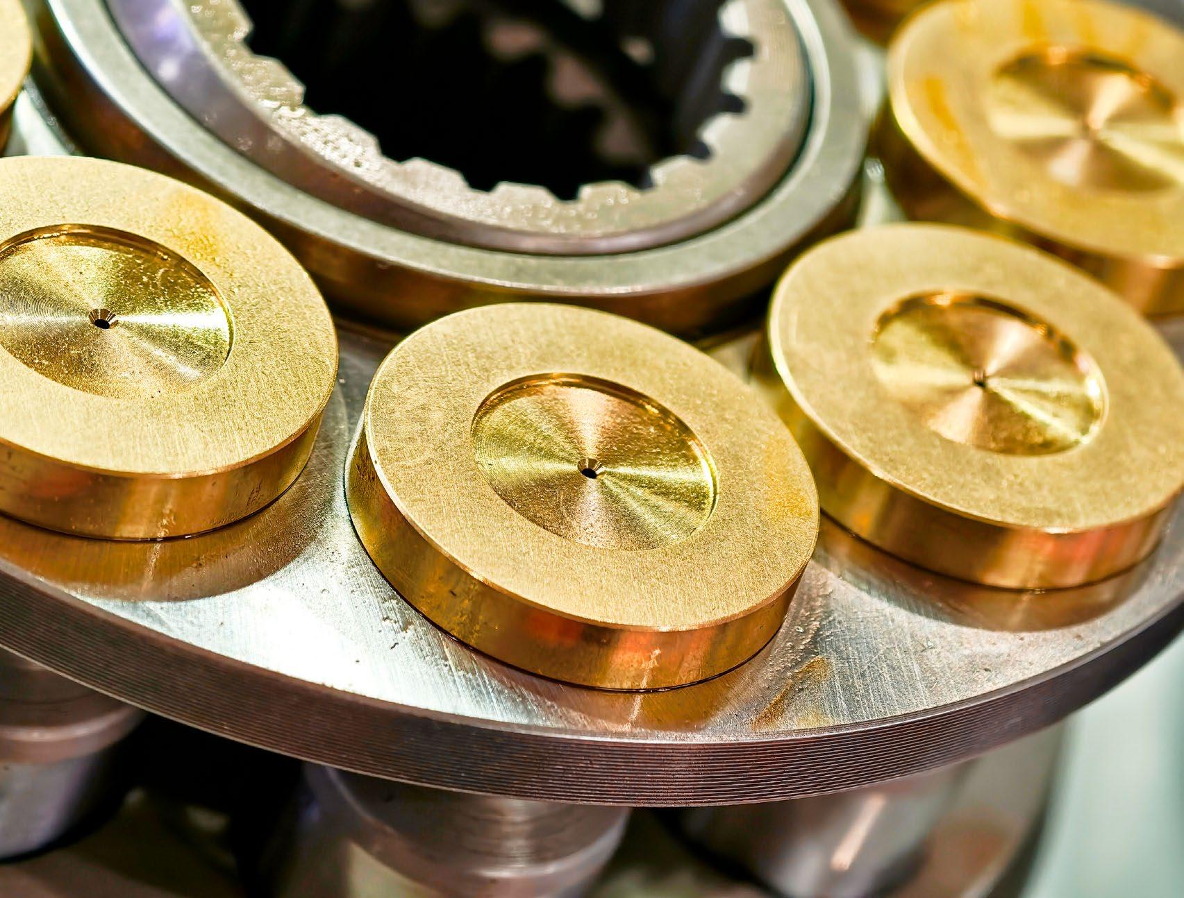
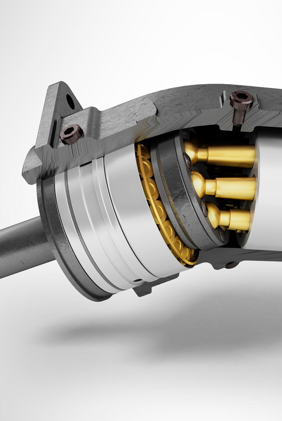
Many fluid power engineers eventually need to plan a high-pressure piston pump rebuild project or ensure affected components return to original equipment manufacturer performance. Developing a proactive approach saves time and money by helping professionals anticipate how they will address these problems once they arise. Here are the most practical ways to proceed and how they impact the overall results.
Those who work with hydraulic piston pumps understand that it is better to detect problems before components require repair than to wait until they cause operational failures. That is why many fluid power engineers get the best results by adopting a proactive mindset to complement their extensive field experience. Increasing awareness of abnormal behavior helps them achieve better overall performance by allowing them to address unusual symptoms more quickly, saving time and money.
Detailed maintenance programs will occasionally reveal problems that require immediate fixes to maintain performance and safety. In these moments, engineers need urgent, around-the-clock support to minimize operational disruptions. Some repair specialists maintain a 24/7 team of factory-trained technicians to diagnose a range of piston pump issues. This approach is designed to quickly address problems, test the hydraulic
system, and ensure it returns to optimal performance with minimal downtime.
Although it is always a good practice to establish relationships with providers of piston pump rebuild services, maintenance teams should strongly consider implementing technologies to increase the likelihood of detecting problems sooner. Internet of Things (IoT) advancements allow technicians to receive instant notifications of issues, such as sudden drops in hydraulic pressure. The appropriate parties can then begin investigating problems immediately, shortening downtime and associated costs.
IoT sensors provide reliable information to inform fluid power professionals when they may need to schedule piston pump repair services. They will then have more flexibility, enabling them to send or drop off the faulty components before failures occur. Connected technologies do not replace repair expertise, but they improve overall awareness.
Although many providers advertise piston pump rebuilding services, not all provide detailed information about their processes. That information gives potential clients confidence that a particular company is a strong choice with extensive experience. It also reassures customers that they are getting their money's worth and can trust the outcomes.
Unusual noises, overheating, pressure drops, and foamy hydraulic fluid are some
of the telltale signs of faulty hydraulic pumps. However, other issues share those symptoms, and fluid power engineers should not assume the pumps are the problem without getting a trustworthy diagnosis.
A truly thorough repair process should be transparent from start to finish, giving full visibility and control. A four-step process begins with technicians fully disassembling and inspecting every component before sending a comprehensive quote listing all required replacements. After the repairs are complete, specialists reassemble, inspect, and test the piston pumps, ensuring they perform as expected and provide trustworthy results.
Parties who need hydraulic repairs on high-pressure piston pumps should consider asking whether providers can produce hydraulic components and replacement parts onsite. These are often necessary when clients need to restore pumps to OEM performance standards. An in-house facility shortens time frames and gives the brand constant control over the production process.
Many fluid power professionals understand the importance of data in maintaining OEM performance standards. Keeping statistics on the type of maintenance, when, and how often repairs occur helps decision makers determine whether a repair or replacing the component is the best option.
Cloud-based systems maintain the accessibility of digital records, making them available to authorized users on any platform. This capability means technicians can retrieve individual records from the field and let the associated information inform their processes. Storing data in the cloud is especially useful if professionals oversee assets at multiple locations, or if a brand has several maintenance teams across numerous states.
This data-driven mindset should extend to repair providers as well. Fluid power professionals should look for entities that provide their own digital service records to supplement internal data. If a company completes extensive repair and upgrade services, the work includes a detailed service log file for each pump. This external record provides another layer of valuable data, helping industrial leaders track trends and document the component's full lifecycle.
Creating a reliable system for logging maintenance and repairs for every piston pump helps industrial leaders track valuable trends and gain important takeaways, such as how long a component will last under typical usage
conditions or whether brands provide more consistent performance than others.
Accurate records are also useful for streamlining personnel changes. They ensure that new high-level maintenance staff members have the information needed to begin their jobs with confidence and get to know the systems under their oversight. The relevant data also eliminates confusion by allowing people to quickly retrieve details prior to repairs.
High-quality hydraulic repairs happen when providers combine their experience with a commitment to continuous improvement. That may mean the technicians regularly upgrade their skills to keep pace with changing technologies and applications. It also often entails achieving consistency in internal processes. Asking repair personnel about the decisions they make to uphold quality helps fluid power authorities find service providers worth their time, money, and trust.
Technicians should photograph all incoming pumps from multiple angles, gathering visual data that serves as a crucial reference point. Later in the process, they may check the images to ensure they can reassemble the pumps in the correct configurations and reattach all accessories, preventing errors and ensuring a precise restoration.
Quality control measures should also occur at earlier stages. For example, when technicians verify which pump issues they must address, they should thoroughly clean all components and note which parts fall outside their required specifications. The repair team can then flag those for potential replacement. A detail-oriented approach delivers comprehensive service and returns high-pressure piston pumps to OEM performance standards.
Fluid power professionals should also recognize the worth of comprehensive testing to verify that components meet or exceed OEM performance standards. The variables studied may include base pressure, pumping speed, pump temperature, and several other aspects. If customers get copies of the final test reports to supplement their internal records, the details within will demonstrate that a company takes quality control seriously and allows customers to see the outcomes of industrial hydraulic repairs.
Because many industrial hydraulic repair specialists provide service across the country
and the world, it is not always easy for decision-makers to narrow down the possibilities. To help make this process easier, look for providers whose services include the key features of a successful and trustworthy high-pressure piston pump repair.
A high-quality restoration process should always include a multi-stage inspection process: The pump should be completely disassembled, and all components cleaned and thoroughly inspected to identify the root cause of the failure. You should receive a detailed quote listing all necessary repairs and replacement parts before any work begins, giving you full control over the decision. The ability to produce necessary hydraulic components on-site ensures that parts meet OEM standards and shortens the project time frame.
After reassembly, the pump must be rigorously tested for base pressure, temperature, and speed to verify it meets or exceeds original performance standards. Reputable providers will stand behind their work with a warranty on all repairs and replaced components. You should receive a final report, including testing results and a digital service log, to add to your own asset records.
Leading hydraulic piston pump repair specialists offer excellent transparency about their expertise and approaches. That information helps them build long-term relationships with customers throughout industries and locations. Many also provide details about how people should ship or drop off their pumps for assessment. The more information prospective new customers can immediately access, the easier it is to gain their trust and business.
Whether a fluid power professional needs a full piston pump rebuild or a specific industrial hydraulic repair, they should begin by analyzing the impacts of having the affected equipment temporarily out of service and respond accordingly. It may also be appropriate to schedule the equipment outage to coincide with periods that have been historically slower for the affected businesses.
Professionals will garner the best results if they confirm details such as budgets, timeframes, and desired service plans with decision-makers who have budgetary authority. Providing that information to leaders sets accurate expectations and leads to productive discussions about industrial requirements and how restoration experts can meet them. •
What determines whether a piston pump should be rebuilt or repaired?
Whether a piston rebuild or repair is more appropriate depends on the severity of damage or fault in the affected components. Experienced technicians know how to diagnose the type and extent of the issues to provide reliable advice on how to proceed.
What are the top signs it’s time to schedule a hydraulic piston pump repair?
If a fluid power professional notices strange noises, pressure drops, worn bearings, or seal deterioration, a hydraulic piston pump may require repairs.
How long should a piston pump last?
New piston pumps usually last several years or more when maintained properly. Expectations differ for repaired or restored components, but reputable providers often issue warranties to support their work.
By Likhit Meshram, Senior Associate Consultant, Fairfield Consultancy Service (OPC) Pvt. Ltd
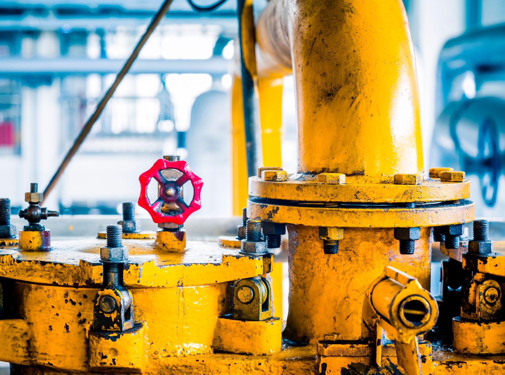
High-pressure hydraulic components form the structural and functional backbone of modern heavy-duty equipment across transportation, industrial processing, and material handling sectors. Trucks operate hydraulic tipping systems at pressures of 28 – 35 MPa (4,000 – 5,000 psi). Railroad vehicles use hydraulic braking and actuation systems. Additionally, presses and foundry machines completing high-force forming operations rely on hydraulic power for reliable, repeatable performance. These systems enable lifting, braking, clamping, forming, and precise positioning functions that are often impractical or inefficient when attempted with purely mechanical or electric actuation. This dependence continues to intensify as equipment size, load ratings, and productivity demands increase across global industries.
The operating environment of heavyduty hydraulic systems is inherently severe. Components are exposed to continuous cyclic pressurization, high static loads, rapid load reversals, and harsh conditions such as dust, vibration, moisture, and extreme
temperatures. Under these stresses, even well-engineered components experience progressive degradation. When failures occur, the impact extends beyond equipment downtime, creating serious safety risks, production disruptions, reduced operational efficiency, and significant direct and indirect financial losses.
Despite advancements in materials, sealing technologies, and manufacturing methods, hydraulic failures remain a leading cause of unplanned downtime in heavy-duty applications. Many failures are still treated as isolated incidents, resulting in component replacement without investigating root causes. This reactive approach often leads to recurring breakdowns, rising maintenance costs, and reduced equipment availability, even though most failures develop gradually through identifiable mechanisms. Failure analysis provides a structured approach to understanding these mechanisms. When combined with disciplined reconditioning practices and guided by standards such as ISO 4413, API 510, and SAE J1273, it enables reliable restoration while preventing repeat failures.
Hydraulic systems operating in heavy-duty service are subjected to extreme mechanical and fluid stresses that significantly influence reliability and service life. System pressures commonly exceed 21 MPa (3,000 psi), with short-duration pressure peaks often surpassing nominal design limits. These conditions are combined with high flow rates and frequent directional changes, producing complex, uneven loading across pumps, valves, actuators, and piping networks.
Transient loading is a major challenge. Rapid load changes, emergency stops, and abrupt valve closures generate hydraulic shock and pressure spikes that accelerate seal extrusion, metal fatigue, and accumulator degradation. Although immediate failure may not occur, repeated exposure substantially shortens component life. In systems lacking effective surge protection, pressure spikes can exceed 120% of nominal operating pressure, forcing components beyond their design envelope.
Fluid contamination remains the leading cause of failure. Solid particles from assembly, maintenance, or wear disrupt lubrication films in close-tolerance components, causing abrasive wear, increased leakage, and efficiency loss. Water contamination further reduces lubricity and promotes corrosion, oxidation, and acidic byproduct formation, often progressing unnoticed. Thermal stress also plays a critical role. Fluid temperatures above ~80°C (175°F) reduce viscosity, accelerate oxidation, weaken elastomers, and reinforce leakage-driven heat buildup. Over time, cyclic loading, misalignment, vibration, and poor installation or maintenance practices intensify mechanical wear and fatigue, ultimately leading to deformation or sudden failure.
While many failure drivers are common across hydraulic systems, individual high-pressure components exhibit distinct failure characteristics shaped by their specific function, construction, and operating environment. This makes component-level understanding essential for accurate fault diagnosis and effective reconditioning strategies. Hydraulic pumps and motors are especially sensitive to fluid contamination and inlet conditions. In high-pressure service, abrasive particles and degraded lubrication films accelerate wear of gears,
pistons, slippers, and valve plates. This leads to increased noise, vibration, and a measurable loss in volumetric efficiency. Cavitation damage, typically caused by insufficient inlet pressure or restricted inlet lines, produces localized pitting and surface erosion. In addition, overpressure events can overload bearings or initiate cracks in housings, resulting in sudden and often catastrophic failure when structural limits are exceeded.
Hydraulic cylinders most commonly fail through seal degradation, rod surface damage, or bore wear, with external leakage often serving as the first visible indicator. Internal leakage, misalignment, and side loading further reduce load-holding capability and promote uneven wear, increasing the risk of rod bending. In high-force press and foundry applications, cyclic pressurization near design limits encourages fatigue cracking in welded joints and deformation of tubes or end caps, particularly where weld geometry is inadequate or post-weld heat treatment is absent. Valves represent another critical vulnerability. Precise internal clearances are easily disrupted by solid contamination and varnish deposits, causing spool sticking, internal leakage, pressure instability, and hidden energy losses. Hoses, tubing, and accumulators complete the failure profile, where aging, vibration, pressure cycling, gas loss, and seal degradation elevate rupture risk, reduce energy storage effectiveness, and increase overall system safety hazards.
Failure analysis plays a critical role in preventing repeat breakdowns and enhancing the long-term reliability of hydraulic systems. The process begins with a thorough review of operating conditions, including pressure levels, temperature trends, duty cycles, and recent maintenance history. This contextual evaluation helps determine whether components were functioning within their intended design limits or exposed to abnormal operating conditions that accelerated degradation. Initial visual inspection offers valuable diagnostic clues. External oil leakage often indicates seal wear, cracking, or deformation, while corrosion or surface pitting can signal internal wall thinning that may require ultrasonic thickness measurement. Visible cracks or deformation demand immediate non-destructive examination. Wear patterns, discoloration, and fracture surfaces further reveal dominant failure mechanisms. Uniform scoring is typically associated with abrasive
contamination, localized pitting points to cavitation or corrosion, and heat-related damage, which is identified by hardened seals, darkened fluid residues, or surface discoloration.
Component teardown enables close inspection of internal surfaces and precise measurement of critical dimensions. Comparing these measurements with original specifications highlights the severity and progression of wear. Frequently, analysis reveals that multiple degradation mechanisms act simultaneously, underscoring the importance of addressing system-level root causes rather than focusing solely on the failed component.
Fluid analysis is central to hydraulic failure investigation. ISO 4406 particle counts assess contamination severity and filtration performance. Water content exceeding 500 ppm requires corrective action, while levels above 1,000 ppm indicate imminent seal failure. Viscosity, total acid number, metal particle analysis, pressure and flow testing, and non-destructive evaluation collectively isolate wear sources, functional defects, and structural integrity issues in critical components.
Reconditioning offers a technically robust and cost-effective alternative to full component replacement when the structural integrity of high-pressure hydraulic components is sound. The process involves complete disassembly, meticulous cleaning, detailed inspection, replacement of worn parts, and precision re-machining of critical surfaces in line with manufacturer and industry standards.
Pump reconditioning starts with disassembly and inspection to identify wear patterns. Components such as pistons, cylinders, vanes, bearings, and valve plates are replaced as required, while critical clearances are restored through precision machining. Reassembly follows strict cleanliness and torque specifications, and functional testing is carried out at design pressure using clean hydraulic fluid. With effective contamination control, reconditioned pumps can deliver several thousand additional operating hours.
Cylinder reconditioning extends the life of costly actuators through honing or boring of internal surfaces, polishing or re-chroming of rods, and seal replacement selected for pressure and temperature compatibility. Structural integrity is verified through pressure testing at 1.5 times the design pressure. Hose replacement adheres to SAE J1273 practices, ensuring correct selection, routing, and proof testing. System-level
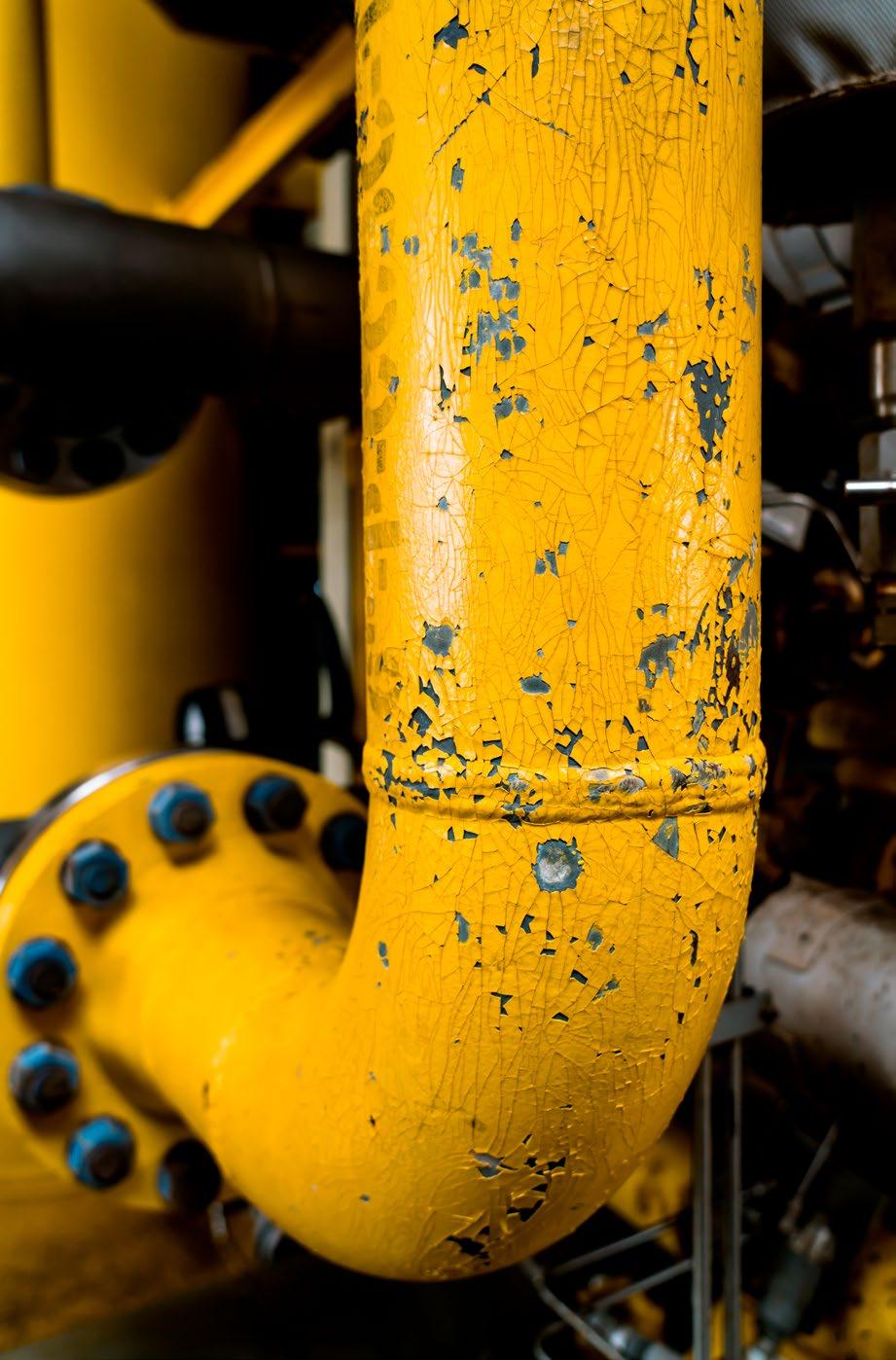
reconditioning prioritizes fluid cleanliness, accumulator recertification, and pressure relief valve recalibration, often incorporating design improvements to enhance long-term reliability and safety.
Failure analysis and reconditioning of high-pressure hydraulic components in heavy-duty applications represent a mature discipline grounded in mechanics-based understanding, systematic diagnostics, and adherence to international standards. By identifying fatigue mechanisms, controlling contamination, managing thermal stress, and applying structured reconditioning practices, operators can significantly extend component life while reducing downtime and safety risk.
The transition from reactive repair to proactive condition-based maintenance delivers long-term reliability and economic benefits. When failures do occur, disciplined reconditioning informed by detailed diagnostic data restores components effectively while preventing recurrence through targeted design and maintenance improvements. For heavy-duty equipment operators across trucking, rail, presses, and foundry sectors, adopting evidence-based failure analysis and reconditioning practices is not merely operational improvement but an essential strategy for sustainable and safe hydraulic system performance. •

By Lauren Schmeal, Editor, Fluid Power Journal As presented by Ken Dulinski, CFPAI, CFPJPP, CFPHS
Eurocard Valve Amplifier Setup, Tuning, and Troubleshooting
Valve amplifiers are a central component in electrohydraulic control systems, providing precise management of proportional valves across industrial markets. The Eurocard format, governed by DIN 41612 standards, remains widely used due to its modular block layout, interchangeable connectors, and standardized pin configurations. While manufacturers vary in pin and section labeling (e.g., Parker/Rexroth A/B/C, others Z/B/D), the core operational principles and block diagram structure are consistent throughout.
Eurocard amplifier cards are typically rack-mounted, streamlining installation and servicing, and their consistent wiring allows simple crossbrand substitutions.
Eurocard amplifiers exist in several model variants, each with distinct control features. The standard configuration includes:
• Basic proportional control cards for standard valve actuation
• Enhanced models featuring multiple command inputs, built-in switches for input selection and polarity adjustment, and optional feedback via LVDT (Linear Variable Differential Transformer) position sensors.
Various amplifier models are complemented by manufacturer-supplied data sheets, outlining setup parameters, wiring guides, and block diagrams for both rack-mounted and modular configurations.
Proper supply and wiring are essential for stable card operation. Regulated 24VDC power supplies are preferable, with ripple content verified by oscilloscope to prevent false voltage readings and system instability. All signal grounds must be correctly tied; reference and command sources (for example, PLC or computer inputs) must share a common ground, or the amplifier will reject command signals.
Initial startup should be validated by monitoring indicator lights:
• Green (“Power On”): Verifies supply voltage is present.
• Green (“DC-DC Converter”): Indicates internal regulated voltage is active.
• Yellow (“Enable”): Shows that the amplifier driver is active.
• Red (“Current Overload” or “LVDT Failure”): Diagnoses faults, wiring errors, or signal failures.
Eurocard amplifiers accept several types of command inputs, typically 0–10V analog signals, allowing direction selection and ramped motion profiles. Proper potentiometer sizing is required to avoid overloading the input circuitry (4kΩ minimum, 5–10kΩ recommended). Shielding and cable insulation are critical to suppress electrical noise, prevent erratic valve behavior, and maintain reliable signal amplification across all proportional solenoids.

Signal Processing Path
Valve amplifier block diagrams consist of sequential processing modules:
• Preamp: Matches input signal level for subsequent processing.
• Gain Control: Separate adjustments for extension and retraction directions, managing force or flow profile as required.
• Ramp Module: Independently adjustable for acceleration and deceleration, limiting spikes and protecting mechanical components.
• Deadband Compensation: Mitigates spool overlap and nonlinearity, supporting immediate actuator movement when the command is applied.
• Pulse Width Modulation (PWM): Drives proportional solenoids efficiently, controlling average current and enabling fine control.
• Dither Addition: Optional AC signal for friction reduction and improved responsiveness.
Monitoring points at amplifier stages enable diagnostics through scope comparisons or test meters, illustrating real-time signal transformation.
Outputs from amplifier cards are routed to proportional valve solenoids, with polarity management and LVDT feedback ensuring proper operation. Pin assignments for solenoid control must be strictly followed to prevent stuck actuators or continuous power faults. Current feedback indicators provide visual assurance of functional wiring and solenoid performance. Output drive capacity, wire sizing, and solenoid ratings (including current and voltage requirements) are also essential considerations for safe and effective circuit design.
Deadband and Gain Adjustment Set-up centers on two main adjustments:
• Deadband Compensation: Set thresholds to eliminate nonresponsive actuator travel, correlating command input with instant movement at spool edges.
• Gain Adjustment: Calibrate signal gain to align maximum input voltage with full valve output, producing consistent flow and actuator motion. Excess gain may force rapid responses. Reducing gain tempers operator control where necessary.
Visual feedback through characteristic flow curves (input vs. actual output) informs adjustments and confirms linear performance. Ramp timing adjustments ensure smooth transitions, mitigating damaging step changes in actuator motion.
Built-in troubleshooting aids include:
• Power, enable, and fault indicators for immediate error isolation.
• Auto-reset features for current overload or feedback loss, clearing faults and restoring function when conditions normalize.
• Test points for voltage and current, enabling intuitive diagnosis of output response and feedback circuit integrity.
Reference to manufacturer-provided data sheets (with downloadable PDFs) further expedites troubleshooting, allowing pin-by-pin tracking and configuration checks.
While pin and signal labels may differ among major brands (e.g., Parker/Rexroth versus Eaton/Vickers), Eurocard amplifier function and troubleshooting remain universally accessible. Legacy and advanced cards offer command selection switches, multi-input compatibility, and enhanced ramp settings to suit application needs.
• Metal tools must be avoided near energized adjustment terminals to prevent accidental shorts and hardware destruction.
• Correct wire gauge, signal grounding, and staged enable logic are necessary for safe startup and tuning.
• Input signals from external sources must be referenced to amplifier ground for proper behavior.
Eurocard valve amplifiers deliver versatile, precise control for proportional hydraulic valves, supporting legacy and modern fluid power applications. Block diagram analysis, strict wiring practices, signal tuning, and use of built-in diagnostics form the backbone of effective maintenance and performance optimization. By focusing on detailed amplifier configuration, signal management, and stepwise tuning, engineers and technicians can maximize fluid power system reliability and control accuracy. The Eurocard standard’s broad adoption, combined with technical documentation and standardized troubleshooting aids, makes it a pragmatic solution for both new installations and field replacements across electrohydraulic control environments. •
By Daniel Pascoe, on behalf of Vacuforce, LLC
» ACROSS PREVIOUS ARTICLES in Fluid Power Journal, I’ve covered a wide range of vacuum-related products and real-world applications, all aimed at highlighting what I consider to be best practices in vacuum system design. In this piece, I want to step back and revisit the core building blocks that make up a typical vacuum pick and place system, providing a more detailed and practical overview to help guide proper component selection and overall system design.
At Vacuforce, much of our work involves supplying individual components and developing complete end-of-arm tooling (EOAT) solutions. Through that process, one thing becomes consistently clear, system performance is rarely dictated by a single component, but rather by how well each element works together as a complete vacuum system.
Often referred to as vacuum generators or ejectors, venturis provide an effective alternative to traditional electric motor vacuum pumps, depending on the application. They operate by directing compressed air, typically between 350 kPa and 620 kPa (50 psi and 90 psi), through a small orifice ranging from approximately Ø0.5 mm to Ø3 mm (Ø0.019" to Ø0.118"). This high-velocity airflow creates a localized pressure drop at the vacuum port, generating suction.
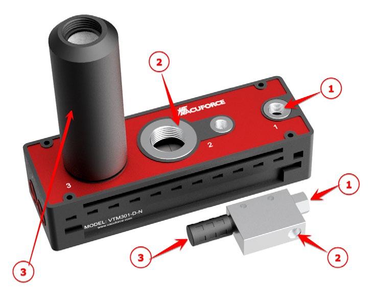
their compact size, instant response, and lack of moving parts. This makes them particularly suitable for decentralized vacuum generation directly at the tooling, rather than relying on centralized vacuum pumps.
The key difference between single-stage and multistage designs is efficiency. Multistage venturis are engineered to maximize airflow entrainment, allowing them to deliver higher vacuum flow with reduced compressed air consumption. This makes them the preferred choice in larger vacuum tools, including multi-cup EOAT assemblies and universal grippers where consistent flow across multiple sealing points is required.
When selecting a venturi, the focus should be on flow rate rather than ultimate vacuum level. In real-world handling applications, leakage is inevitable, whether from porous materials, imperfect seals, or dynamic movement. Flow is what maintains grip under those conditions. Sizing is typically determined by the number of vacuum cups, the length and diameter of vacuum tubing, and the required cycle time. These factors dictate how quickly vacuum must be achieved and how effectively it can be sustained.
In most vacuum cup handling applications, a vacuum level above 30 mm Hg (15") Hg is sufficient, and anything exceeding 600 mm Hg (24") Hg typically results in unnecessary energy consumption. As a guideline, each square inch of effective sealing area can generate approximately 31 N (7 lbs.) of lifting force at 30 mm (15") Hg. Designing systems around flow rather than chasing higher vacuum levels often results in more efficient and reliable EOAT performance.
Vacuum filters are essential for protecting system components from dust and particulate contamination. In EOAT and pick-and-place applications, debris from cardboard, wood, or packaging materials can quickly enter the vacuum circuit and degrade performance if not properly managed. Filters are available in various designs and filtration levels, typically ranging from 7µ to 25µ. For reference, a 7µ (µ = micron) filter captures particles larger than 0.007mm. A size comparison of common filter types is shown in Figure 2.
From an application standpoint, filtration strategy should be considered early in the design phase. In decentralized vacuum systems, such as those used in robotic EOAT, point-of-use filtration is often preferred to protect individual venturis and prevent contamination from propagating through the system. Point-of-use filters are typically installed directly between smaller single-stage venturis and the vacuum cups. Inline filters, often made of plastic with transparent housings, are used in higher-flow applications up to approximately 180scfm, offering both protection and visual inspection capability. Larger industrial filters, as per Figure 2, are used with vacuum pumps and can accommodate pipe sizes from 9.5 mm to over 200 mm (3/8" to over 8").
Regardless of filter type, the function remains the same, however proper selection must be based on flow requirements. Filters should always be sized according to flow capacity, not port size. For example, if a 566 Nlpm (20 scfm) venturi is supplying 5 vacuum cups, each fitted with its own inline filter, then each filter should be capable of handling at least 113 Nlpm (4 scfm), assuming the cup fittings themselves can support that flow. If they cannot, this indicates that the venturi is oversized for the application.
Undersized filters will create a restriction within the system, increasing evacuation time and reducing overall responsiveness. This becomes particularly evident in high-speed automation or applications involving multiple product types, where consistent and rapid vacuum performance is critical.
A vacuum system without a gauge is essentially operating without feedback. In practical terms, this makes both troubleshooting and optimization extremely difficult. In EOAT applications, especially those handling a range of products or materials, monitoring vacuum level at the point of use is critical. A basic vacuum gauge provides immediate insight into system performance and should be considered a standard inclusion.
A comparison between a compact, pointof-use single-stage venturi and a larger multistage unit is shown in Figure 1. As indicated, the three main ports are compressed air inlet, vacuum inlet and exhaust. From a practical standpoint, venturis are widely used in EOAT applications due to
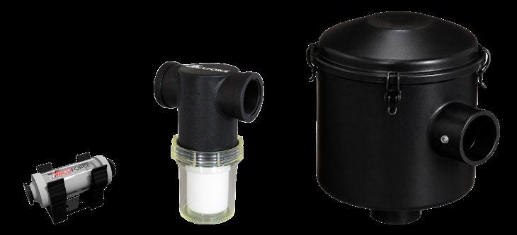
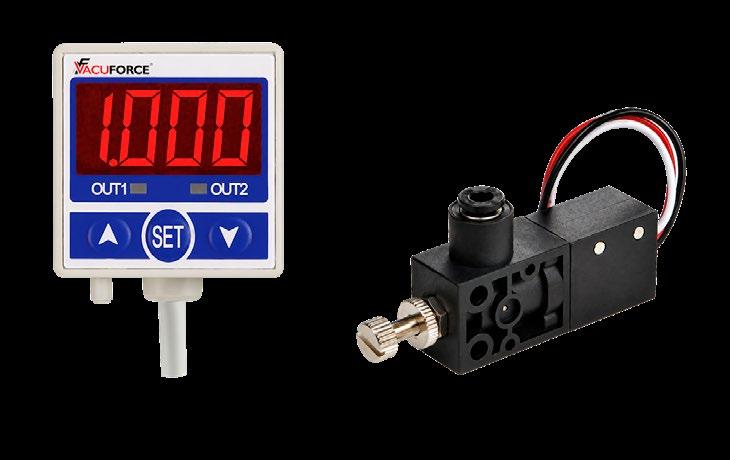
While gauges provide visual feedback for operators, vacuum switches and sensors enable automated decision-making within the system. These devices communicate with the PLC, allowing the machine to confirm successful pickup before proceeding with movement. Figure 3 shows several types of vacuum switches. While all serve the same purpose, they differ in output type and construction. The digital models on the left offer precise electronic feedback, often with adjustable setpoints and integrated displays. The diaphragm switches on the right provide a simple and robust alternative, particularly suited to less complex systems. In many EOAT designs, particularly those used in high-speed or safety-critical applications, reliable vacuum sensing is just as important as vacuum generation itself.
A wide variety of vacuum cup designs are available, with several common types shown in Figure 4. In many cases, the vacuum cup is the most application-specific component in the system and has the greatest influence on overall performance. The most widely used style is the single bellows cup (#1). This design accommodates variations in product height and approach, making it highly versatile for general-purpose handling.
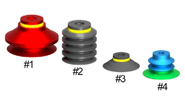
Multiple bellows cups (#2) extend this flexibility further, allowing the cup to compensate independently of machine movement. This is particularly valuable in applications such as thin sheet separation or handling flexible packaging, where maintaining a seal during deformation is critical. Flat cups (#3), while requiring more precise positioning, provide superior stability once engaged. This makes them well suited for high-speed handling or applications involving directional movement, such as transferring products from horizontal to vertical orientations.
Material selection is equally important. Nitrile rubber (NBR) is suitable for general-purpose applications. Silicone is commonly used for temperature extremes and food handling. Polyurethane offers
excellent wear resistance in high-cycle environments. Some designs incorporate dual-durometer construction (#4), combining a rigid body with a soft sealing lip. In more advanced EOAT designs, particularly those involving mixed product handling, multiple cup styles or configurations may be combined, or replaced entirely by universal gripping solutions that rely on distributed vacuum flow rather than discrete sealing points.
Vacuum valves are often underutilized but can significantly improve both system efficiency and performance. By allowing the system to reach full vacuum prior to engagement, valves enable the vacuum source to be isolated during the holding phase. In venturi-based systems, this allows compressed air to be shut off once vacuum is achieved, reducing overall energy consumption. In EOAT applications, placing valves as close as possible to the vacuum cups minimizes system volume and improves response time. This results in faster engagement and release, which is critical in high-cycle automation.
introduce compliance into the system, allowing individual cups to adjust to variations in product height or surface alignment. This is particularly beneficial in multi-cup EOAT designs, where consistent contact across all cups cannot always be guaranteed.
Level compensators should be used strictly for vertical lifting applications and should not be rotated through 90° unless specifically designed for that purpose, as this can lead to premature wear. In addition to functional benefits, they also simplify integration into tooling structures, allowing for clean mounting through plates or extrusion-based EOAT frames.
All the components discussed play a role in a well-functioning vacuum system. However, in practical applications, especially in robotic handling and automation, performance is defined by system integration rather than individual component capability. A few key principles should always be considered:
• Venturis and filters should be matched based on required flow.
• Flow rate is determined by the number of vacuum cups and cycle time.
• Valves should be installed as close as possible to the vacuum cups.
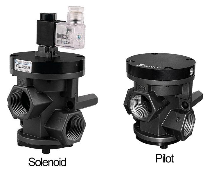
5
• Gauges should be positioned near the cups for accurate readings.
• Switches should be located near the gauge for effective system control.
At Vacuforce, these principles form the foundation of how EOAT systems are designed, whether for simple pick-andplace operations or more advanced universal gripping solutions where adaptability and consistency are critical.
Most vacuum valves are electrically actuated solenoid types, as shown in Figure 5. These offer fast response and straightforward integration into control systems. Pneumatically piloted versions are also available and are commonly used in fully pneumatic environments where electrical components are not suitable.
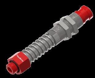
6
While many vacuum cups are supplied with threaded connections, more complex tooling arrangements often require level compensators, as shown in Figure 6. These components
This article is intended as a general reference. As with any industrial system involving equipment selection and integration, independent professional advice should be considered to ensure optimal performance, efficiency, and safe operation.
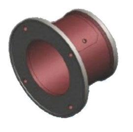

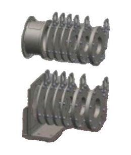
BSF, Inc is your premier supplier of electromechanical and hydraulic flange-to-flange connections. We are able to mate almost any flange-to-flange application with numerous configurations, styles, and options.
937-890-6121
MOCAP manufactures an extensive range of protective closures to guard pipes, hoses, and hydraulic fittings from dirt, moisture, and damage to help maintain equipment reliability. Included are a variety of sizes and styles of Threaded and Non-Threaded plastic Caps and Plugs for Metric, NPT, BSP, JIC and SAE Threaded Connections, Ports and Fittings. These are in addition to MOCAP’s already extensive lines of lowcost Caps, Plugs, Grips, Netting, Tubing and Tapes for general Product Protection, Finishing and Masking.
All of our stocked items are ready for immediate shipment and available in Box, Mini-Pack and Micro-Pack quantities. Free Samples are always available for testing purposes.
sales@mocap.com www.mocap.com
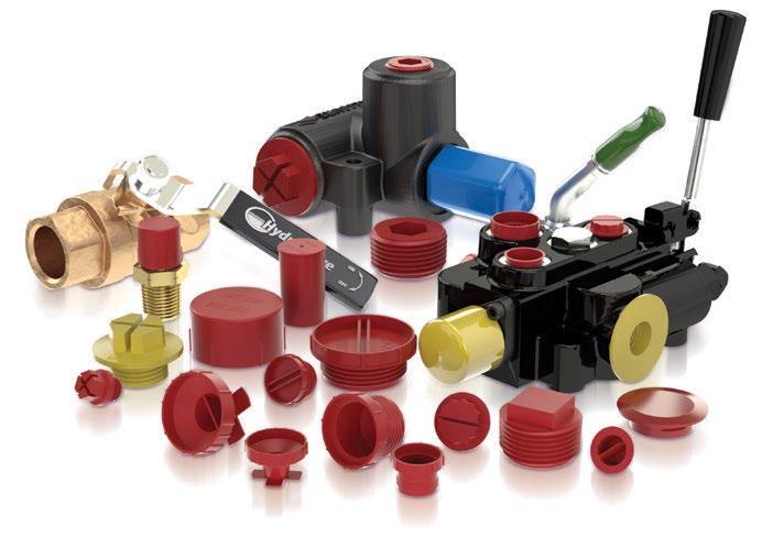

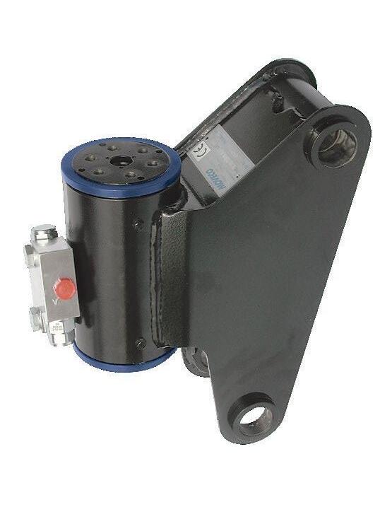
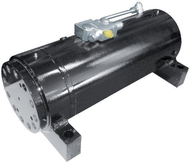
Young Powertech, Italian made Helical Hydraulic Rotary Actuators cover a wide range from 45 to 40,000 LB-FT torque and up to 750 degrees rotation for mobile and industrial applications. Local inventory for quick delivery and service and worldwide support makes it the best option for your rotating applications.

3060 Plaza Dr. #108
Garnet Valley, PA 19060
Telephone: 610-558-0760
Email: info@youngpowertech.com www.youngpowertech.com delivers solutions
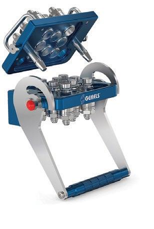
Founded over 55 years ago in Italy, GEMELS is a global leader in ball valves, quick disconnect couplings, and hydraulic valves, combining Italian manufacturing excellence with innovation. With standard and customized solutions, a strong U.S. logistics hub, and a trusted dealer network, GEMELS North America ensures fast, duty-free distribution, competitive pricing, and a long-standing presence in the North American market.

Gemels North America Inc. northamerica@gemels.com gemels.com
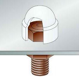
Hex Bolt & Nut Protection Caps are precision-molded from low-density polyethylene (LDPE) to protect exposed fasteners from moisture, UV exposure, and tampering. Designed for secure fitment over hex bolt heads, nuts, and screws, they enhance durability and provide a clean, uniform finish. Offered in black or white for reliable outdoor performance.
800.847.0486 | sales@essentracomponents.com www.essentracomponents.com
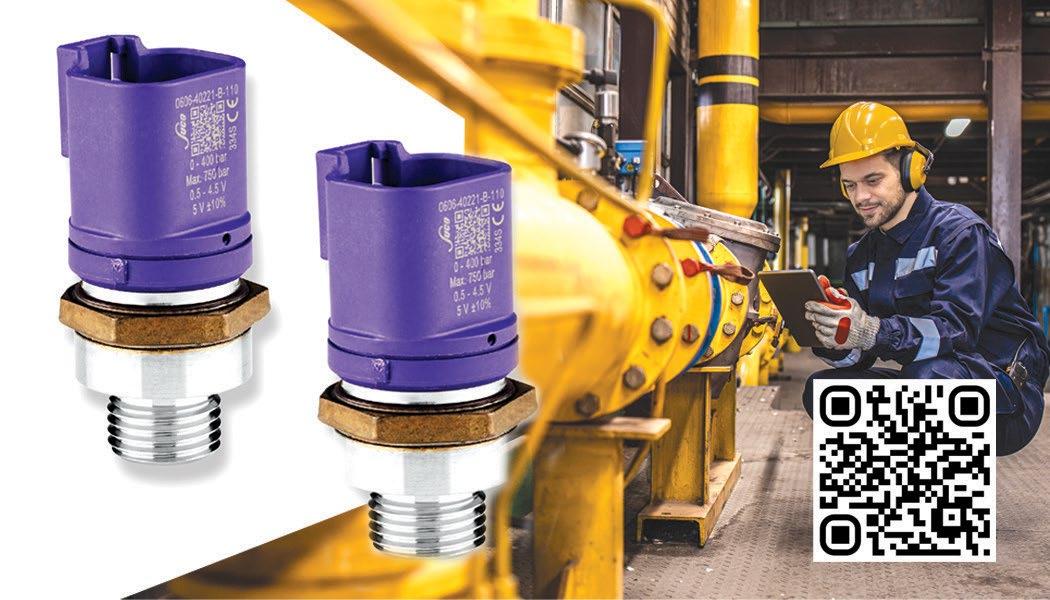
Roth Hydraulics Bladder Accumulators store and release hydraulic energy with precision — delivering reliable pressure compensation, pulsation damping, and emergency operation across the most demanding applications. Available in CE and ASME series, with operating pressures up to 690 bar and a full range of bladder materials and global approvals.
P: +1 281-347-8080
E: info@sfphyd.com W: sfphyd.com SUCO’s OEM
and Precision
• All-welded, leak-proof construction
• Pressure Range: From 0-40 bar to 0-500 bar
• Overpressure Protection: From 150 bar to 1,000 bar
• Low Cost Solution
• Ideal for all mobile hydraulic applications, pump monitoring, transmission systems, and braking systems
561.989.8499 sales@sucoesi.com sucoesi.com/oem
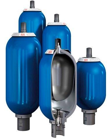
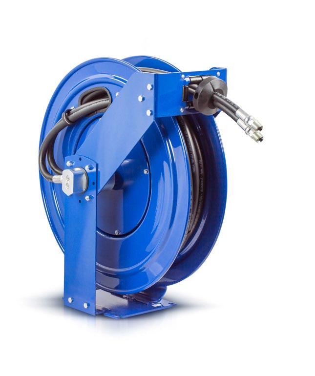
TDPM reel is robustly built for capacities up to 50’, with triple axel support, dual arm guides, and stainless-steel hose guide rollers. As with all Coxreels spring retractable reels, it features heavy gauge steel construction, durable CPC powder coat, rolled and ribbed discs, 2-year warranty, and USA made www.coxreels.com

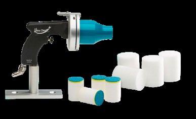
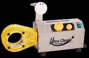
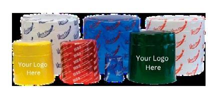
Ultra Clean Technologies provides complete hydraulic contamination control solutions, including our Clean Easy projectile cleaning systems, Seal Easy® capsules to prevent recontamination, and our brand new Insert Easy line of professional-grade industrial and hydraulic stem lubricants. Our products ensure hoses are clean, sealed, and installation-ready.
Learn more at www.ultracleantech.com or call 800-791-9111.

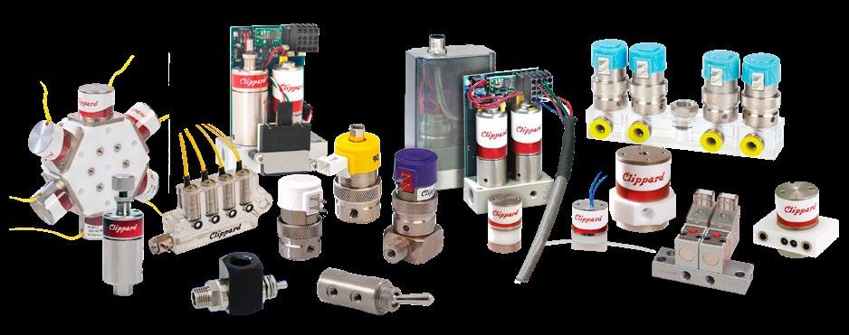
Designing efficient systems is about more than components and specifications—it’s about understanding how real requirements come together in the real world. Clippard takes the time to understand the specific demands of your system, applying decades of engineering experience to deliver solutions that perform better, last longer, and fit seamlessly.
Call or email us today to connect our engineers with yours.
www.clippard.com/link/FPJ 1-877-245-6247 | sales@clippard.com


•
•
•
•

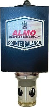


almomanifold.com
» Talk to your account rep or visit fluidpowerjournal.com/advertise
Company Page
Almo Manifold 27
BSF Incorporated IFC, 24
989-984-0800













Web
almomanifold.com
937-890-6121 bsfinc.net
Clippard 1, 26 877-245-6247 clippard.com
Continental Hydraulics/Hydreco IFC
952-894-6400 continentalhydraulics.com
COXREELS 13, 25 1-800-269-7335 coxreels.com
Essentra Components 25, 28 1-800-847-0486 essentracomponents.com
FluiDyne Fluid Power 27
586-296-7200 fluidynefp.com
Gemels North America 24, 28 1-713-257-3671 gemels.com
Main Mfg Products 27 1-800-521-7918 mainmfg.com
MOCAP Inc 24
SFP Hydraulics 10, 25
1-800-633-6885 mocap.com
1-281-347-8080 sfphyd.com
SUCO ESI 25, IBC 561-989-8499 sucoesi.com
Ultra Clean Technologies 26, IBC 1-800-791-9111 ultracleantech.com
Young Powertech, Inc 24, OBC 610-558-0760 youngpowertech.com