POWER
On Rear of Cage
CHASSIS LOOM PLUG connects to Cage loom

FUSED F2 12v
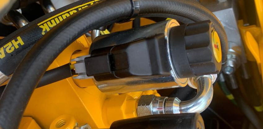
Dual Power Sub-Loom plug behind oil tank
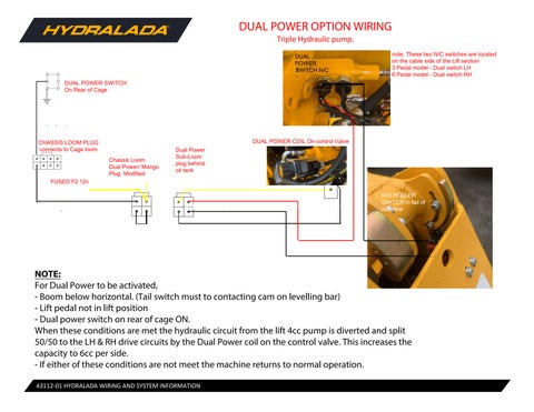
DUAL POWER OPTION WIRING
Triple Hydraulic pump.
DUAL POWER
Chassis Loom Dual Power/ Mango Plug Modified SWITCH N/C
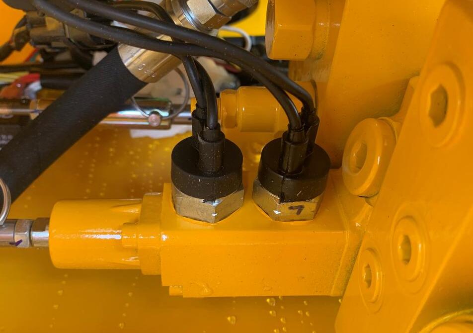
note: These two N/C switches are located on the cable side of the Lift section
3 Pedal model - Dual switch LH
6 Pedal model - Dual switch RH
NOTE:
For Dual Power to be activated, -Boom below horizontal. (Tail switch must to contacting cam on levelling bar) -Lift pedal not in lift position -Dual power switch on rear of cage ON.
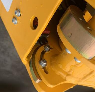
N/O ROLLER SWITCH In tail of machine
When these conditions are met the hydraulic circuit from the lift 4cc pump is diverted and split 50/50 to the LH & RH drive circuits by the Dual Power coil on the control valve. This increases the capacity to 6cc per side.
-If either of these conditions are not meet the machine returns to normal operation.
POWER SWITCH On Rear of Cage
LOOM PLUG connects to Cage loom
FUSED F2 12v
Dual Power Sub-Loom plug behind oil tank