
b!design generic installation instructions for design flooring EN

Page 1


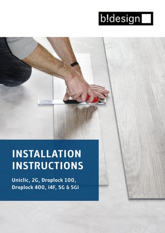
INSTALLATION INSTRUCTIONS

Uniclic, 2G, Droplock 100, Droplock 400, i4F, 5G & 5Gi

IMPORTANT INSTALLATION INSTRUCTIONS

Required room climate during installation

• Relative humidity: 40–65

• Room temperature: 18–25 °C

• Temperature of flooring and installation materials: min. 18 °C

• Subfloor temperature (with or without underfloor heating): 15–22 °C

Area of application

Suitable for rooms with typical residential climate conditions (40–65% RH, 16–24 °C) as well as for damp areas with temporary humidity up to 80% RH, including occasional splash water. Not suitable for wet rooms such as shower cabins and similar areas (permanent moisture, standing water).

Acclimatisation

We recommend storing the product in unopened packaging in the installation area until fully acclimatised. For temperature adjustment, we recommend 48 hours (approx. 3–4 days in winter).

Subfloor

Flatness tolerance: 3 mm over 1 m

Underfloor heating

The flooring elements can be installed over subfloors with underfloor heating. The surface temperature of the flooring must not exceed 32 °C, including edge areas and under furniture or rugs (risk of heat accumulation).

Expansion gap

Maintain a gap of 8–10 mm to walls and around heavy fixed objects such as built-in furniture, wall units or kitchens.

Underlay

mat

The use of an underlay mat is generally recommended. The underlay mat must meet the following requirements:

• Maximum thickness: 1.5 mm

• CS value: > 500 kPa

• Density: > 800 kg/m³

• No anti-slip surface

• Vapour barrier required

For these design floors, we recommend the DB-Cover underlay mat. This underlay mat exceeds all required specifications and includes an integrated vapour barrier. For products with integrated impact sound insulation, additional acoustic improvements are generally not effective and therefore not recommended. For floors with integrated underlay mat, no additional underlay mat may be used.

Expansion joints

The necessity and positioning of expansion joints (e.g. large areas, angled rooms, special structural conditions) should be assessed in advance. Expansion joints can be covered with suitable profiles. These should only be fixed lightly to avoid restricting the floating installation. Structural expansion joints in the subfloor (e.g. between adjoining screeds of different rooms) must be continued in the same position.

No adhesive installation

Design flooring with click systems is intended for floating installation only. Any glued installation will void all warranty claims.

10 tips for perfect floor installation

1. Before installation, the purchased flooring must be checked for defects and color variations. Once the flooring has been installed, all warranty claims are void.

2. Only install on solid, non-floating subfloors. Floating screed in accordance with DIN 18560-2 is suitable as a subfloor, provided it is dry, level and load-bearing (residual moisture must be checked using CM measurement). Floating floor coverings are not suitable as a subfloor.

3. Do not install fixed units such as kitchen cabinets, built-in wardrobes, washing machines or similar items on top of the installed design flooring. The flooring must be decoupled using expansion joints.

4. Use office chairs with soft castors, type W according to DIN 68131, on design floors. We also strongly recommend the use of suitable floor protection mats.

5. Purchase and use the recommended underlay (impact sound insulation / PE film) together with the flooring. Carpet is NOT a permitted underlay.

6. Use spacers to ensure the floor is laid straight and does not shift during installation.

7. Maintain the recommended offset of 30 cm or one plank width between joints in adjacent rows.

8. Expansion joints specified in the subfloor (e.g. between adjoining screeds of different rooms) must be maintained and aligned.

9.

Leave an expansion gap of 8–10 mm along the walls to allow the floor to expand and contract. The gaps can be sealed with PE cord and silicone to prevent cracking. Ensure that the foam cord is placed loosely in the joint without tension.

10. Unless otherwise specified in the installation instructions, the requirements of DIN and SIA standards apply. In addition, the guidelines of MMFA and general industry best practices must be observed.

Basic installation rules

GOOD TO KNOW

Vinyl/SPC flooring is durable, healthy for living environments, and extremely easy to maintain – making it ideal for use in a wide range of residential spaces. The wide variety of decors, formats and surface textures allows you to create a truly individual interior design, with modern looks and an authentic feel for a warm and comfortable living atmosphere.

USE CLASSES

Within European standards for vinyl/SPC flooring, properties, requirements and testing methods are clearly defined. These are presented in a simple and transparent way through use classes. Depending on the achieved results – in line with requirements and the level of wear and usage –flooring is classified into categories for residential use (range 20), commercial/public use (range 30), and industrial use (range 40).

General requirements for subfloors

As a general rule, the contractor responsible for flooring installation, or the private individual carrying out the installation, must ensure – within the scope of their duty of inspection and care – that the subfloor is ready for installation before laying begins. When assessing the suitability of the subfloor for installation, the following points must be taken into particular consideration. Failure to comply will result in the loss of all warranty and guarantee claims.

MOISTURE TESTING OF THE SUBFLOOR:

Moisture testing must be carried out using the CM method. The following limit values must not be exceeded:

• Cement screeds: ≤ 2 CM% – heated screeds ≤ 1,8 CM%

• Calcium sulphate screeds / flowing calcium sulphate screeds: ≤ 0,5 CM% – heated screeds ≤ 0,3 CM%

These values apply to screeds without additives. The screed thickness must be measured and documented.

FLATNESS TESTING OF THE SUBFLOOR:

The flatness of the subfloor must be checked in accordance with applicable standards. For this purpose, place a straightedge or measuring bar on the highest points of the surface. The deviation is then measured at the lowest point relative to the support points (measuring point intervals). At a measuring interval of 100 cm, the maximum permissible vertical deviation is 3 mm. Greater deviations must be corrected by appropriate measures, such as the use of self-leveling compounds.

LOAD-BEARING CAPACITY OF THE SUBFLOOR:

The subfloor must form a continuous, selfsupporting layer.

CLEANLINESS OF THE SUBFLOOR:

The subfloor must be clean and thoroughly vacuumed.

ROOM CLIMATE CONDITIONS:

Before, during and after installation, the following conditions must be met:

• Relative humidity: 40–65%

• Room temperature: 18–25 °C

• Temperature of flooring and installation materials: min. 18 °C

• Floor temperature (with or without underfloor heating): 15–22 °C

All subfloors that meet the previously stated requirements and are considered ready for installation are suitable. These include in particular:

• All types of screeds

• Chipboard constructions

• Wood fibreboards

• Existing floor coverings such as PVC, linoleum, natural stone slabs and ceramic tiles

Conditionally Suitable Subfloors:

• Electric underfloor heating systems (surface temperature control))

Electric underfloor heating systems are classified as conditionally suitable subfloors. This is because some foil-based electric heating systems can generate surface temperatures well above 29 °C.

Approval for electric underfloor heating is granted only if:

• The system is digitally controllable, and It is ensured that the surface temperature never exceeds 29 °C

• In addition, technical approval from the heating system manufacturer for use with design flooring must be provided.

No warranty claims apply for products installed over infrared underfloor heating systems.

DIN EN 1264-2

EN 1264-2 defines the framework conditions and test methods for determining the performance of hydronic underfloor heating systems, depending on the difference between the heating medium temperature and the room temperature.

The heat output is verified both by calculation and by measurement procedures.

NOTE

In all cases, typical indoor living temperatures must be maintained throughout the year in the installed area.

We recommend heating the affected rooms during winter and protecting them from direct sunlight in summer by taking appropriate measures (e.g. blinds or shades).

Failure to comply with these recommendations and requirements will void all warranty and guarantee claims.

Screeds with Hydronic Underfloor Heating

When constructing a heated floor system, all parties involved (client, architect, heating system planner, heating installer, installer, and flooring manufacturer) must work together in a coordinated manner. Every underfloor heating system requires careful planning and coordination with regard to the heating system and the screed, depending on its intended use. This ensures long-term, trouble-free performance and optimal functionality. In addition to the standard subfloor inspections, the underfloor heating or cooling system must be tested for proper operation (functional heating and/or cooling test). Proof of correct heating-up and cooling-down of the screed structure must be provided at all times of the year and documented in a heating and cooling protocol.

When heating the load-bearing or heat distribution layer, a distinction is made between functional heating and readiness-for-installation heating.

• Functional heating serves as proof by the heating contractor that the installation has been carried out without defects. It also verifies the proper functioning of the heated floor construction.

• Readiness-for-installation heating is used to remove residual moisture from the screed until it reaches installation readiness.

Wet Rooms / Moisture-Prone Areas

Design flooring may also be installed in moisture-prone areas – with the exception of saunas. Moisture-prone areas are defined as spaces with temporary humidity levels of up to 80% relative humidity, including occasional splashes of water. These products are not suitable for wet areas such as shower enclosures or similar environments with constant moisture, standing water, or prolonged wet conditions.Particular attention must be paid to the suitability of the subfloor in moisture-prone areas (anhydrite screeds are conditionally suitable; wood-based materials are not suitable).Failure to comply will result in the loss of all warranty and guarantee claims.

DIN 18365

The standard DIN 18365 “Flooring Works” applies to the installation of floor coverings in sheets and tiles made of linoleum, plastic, elastomer, textiles and cork, as well as to the installation of multilayer elements.

When heating the load-bearing or heat distribution layer, a distinction is made between functional heating and readiness-for-installation heating.

• Functional heating serves as proof by the heating contractor that the installation has been carried out without defects. It also verifies the proper functioning of the heated floor construction.

• Readiness-for-installation heating is used to remove residual moisture from the screed until it reaches installation readiness.

NOTE

Functional heating does not ensure that the screed has reached the residual moisture level required for installation readiness. Therefore, readiness-for-installation heating is generally necessary.

Natural Stone and Ceramic Tiles

Rising residual moisture must be expected. Therefore, a moisture protection film with an SD value ≥ 75 m must be installed as a vapor barrier over the entire surface and in a tray-like manner before installing the system-specific underlay (see section: underlay materials).If the design flooring already has an integrated acoustic backing, no additional underlay may be installed. The joints of the tiles must be leveled prior to installation.

Fibreboards

To improve impact sound insulation and protect the click connection, install a system-specific underlay (see section: underlay materials) before laying the design flooring. In addition, a 0,2 mm PE construction film must be installed as a vapor barrier.

Wooden Floorboards

Any loose boards must be properly secured with screws. To improve impact sound insulation and protect the click connection, install a systemspecific underlay (see section: underlay materials) before laying the design flooring. In addition, a 0,2 mm PE construction film must be installed as a vapor barrier.

Resilient Floor Coverings (PVC, Linoleum, Vinyl)

For these types of floor coverings, a moisture protection film is not required. To improve impact sound insulation and protect the click connection, install a system-specific underlay (see section: underlay materials) before laying the design flooring.

Underlay materials

When installing flooring, the correct subfloor is essential. We therefore recommend the use of an underlay. If no underlay is used and the requirements for the subfloor are not met, all warranty claims will be void. The following values are decisive:

DL: REQUIREMENTS FOR DYNAMIC LOAD

Dynamic load (DL) occurs when a room is walked on or when furniture such as chairs is used. The underlay must be able to withstand these short-term loads without permanently changing its properties. This capability is expressed by the DL value. The higher the DL value, the longer the underlay can withstand dynamic stresses. A DL value of 10,000 cycles is recommended. For higher levels of stress, the DL value should be at least 100,000 cycles.

CS, CC AND PC: REQUIREMENTS FOR STATIC LOAD

The CS and CC values define the requirements for static load. Static load occurs when the flooring is subjected to continuous pressure from heavy, stationary furniture. The underlay must be able to withstand high, constant loads without excessive compression. A high CS value is important to maximize the service life of the click joints. The underlay must not compress too much in order to protect the flooring from deformation and damage caused by vertical movement. Accordingly, the CS value must exceed 500 kPa. The higher the CS value, the better the protection against such damage.

For long-term loads, the CC value plays a key role. Heavy furniture that remains in place subjects the floor to permanent stress. The CC value indicates how the underlay performs over a period of 10 years under load. For higher requirements, the CC value should be at least 20 kPa. Furthermore, for an underlay thickness of 1,5 mm, the point load compensation (PC) must not exceed 0,5 mm.

WHY ARE UNDERLAYS NECESSARY?

An underlay only makes sense if it contributes to the overall performance of the flooring system. It forms the interface between the flooring and the subfloor and must therefore meet certain requirements. Its primary function is to compensate for minor unevenness in the subfloor. It also protects the flooring from daily wear and residual construction moisture. In addition to impact sound reduction and walking comfort, thermal insulation also plays an important role. Bei Böden mit integrierter Unterlagsmatte darf keine zusätzliche Unterlagsmatte verlegt werden.

For the installation of our flooring, we recommend the underlay b!design LVT/SPC 1.4

The elastic impact sound underlay stands out due to its exceptional walking comfort and sound reduction performance. Manufactured using state-of-theart technology from recyclable and renewable raw materials, b!design LVT/SPC 1.4 is the ideal underlay for design flooring.

It excels particularly in compressive strength. With a CS value of 958 kPa, it significantly outperforms conventional underlays.

This underlay exceeds all required standards and also features an integrated vapor barrier.

It is easy to handle and install. Thanks to its long service life and maintenance-free performance, b!design LVT/SPC 1.4 offers double benefits. In addition, it impresses with an excellent priceperformance ratio.

For design flooring, the underlay must be installed with the white textile side facing upwards.

Residential conservatories

A residential conservatory is a conservatory designed for year-round use as a living space and therefore intended to maintain comfortable indoor temperatures (above 18 °C). This means that the temperature must not fall below 16 °C, even in winter. In summer, solar heat gain must be controlled through natural shading and/or structural measures such as ventilation, suitable glazing and sun protection, depending on local conditions and orientation, in order to prevent excessive temperature fluctuations of the floor. The following indoor climate conditions must be observed:

• The surface temperature of the floor must not exceed 32 °C.

• Installation may only be carried out on a subfloor that complies with DIN 18365 “Flooring Works”.

• The construction must be permanently protected against rising moisture from the ground.

• The substructure must be sufficiently insulated to prevent damage caused by temperature differences or condensation.

• For screeds, the residual moisture content must be measured using a CM device before installation and must comply with the following limits:

• Cement screed (heated / unheated): 1,8 CM% / 2,0 CM%

• Calcium sulphate screed (heated / unheated): 0,3 CM% / 0,5 CM%

• The subfloor must be checked for installation readiness. It must be level, dry, non-slip, clean, crack-free, free from separating agents, and have adequate tensile and compressive strength.

If a leveling compound is applied to the subfloor, the specified indoor climate conditions, required subfloor preparation (e.g. sanding, priming), and drying times must be strictly observed. Before opening, the packages must be acclimatized. Store them unopened and flat on the floor for approx. 48 hours (in winter approx. 3–4 days) in the center of the room where installation will take place.

The lightfastness of our flooring has been tested in accordance with EN ISO 105-B02 and meets the highest requirements. However, color changes caused by strong and prolonged exposure to sunlight cannot be completely ruled out. The product-specific installation instructions must be followed.

Installation Instructions

KEEP JOINTS CLEAN

When installing design flooring, ensure that all joints are free from dust, dirt, and other contaminants. The cleaner the click connection, the better the connection between the panels.It is best to keep the panels in their packaging until just before installation.

Please note that long-term exposure to continuous temperatures above 32 °C or below 13 °C, for example due to direct sunlight, may damage the flooring.

CHECK THE ENVIRONMENT AND SUBFLOOR

Before installation, the flooring installer must report any concerns identified during the inspection of the subfloor. This applies in particular to:

• Significant unevenness

• Cracks in the subfloor

• Insufficiently dry subfloor

• Subfloor surfaces that are not sufficiently firm, are too porous, or too rough

• Contaminated subfloor surfaces (e.g. oil, wax, varnish, or paint residues)

• Incorrect height level of the subfloor surface in relation to adjacent building components

• Unsuitable subfloor temperature

• Unsuitable indoor climate conditions

• Missing heating protocol for heated floor constructions

• Missing overlap of the edge insulation strip

• Missing marking of measuring points for heated floor constructions

MEASURE THE ROOM

Measure the length and width of the room. If the room has alcoves or recesses, these must be measured separately. This will give you the total floor area. Purchase at least 10% extra material to account for waste, cutting, and replacement. This may vary depending on the size and layout of the room.First, check whether the opposite walls are parallel. If they are not, adjustments can be made to the first row of flooring. Lay out a row of panels loosely to determine whether the length of the first panel needs to be adjusted. To avoid a short piece of less than 30 cm at the opposite wall, measure the length of the room and divide it by the panel length. If the remaining piece is less than 30 cm, calculate half of the remainder and shorten the first panel by this amount. Measure and mark the first panel accordingly. Then use a straightedge and a utility knife to score the panel and snap it off.

USING OFFCUTS

When cutting vinyl flooring panels to length, always ensure that the short side with the groove is cut off. The remaining piece can then be used at the opposite side of the room at the end of the same row – provided the layout allows it.

REPLACING DAMAGED FLOORING

Make sure to keep a few spare vinyl panels in stock in case an unexpected replacement is required. Click-lock vinyl panels can be removed and replaced with new ones. If a panel needs to be replaced, use a utility knife to cut along the long side of the damaged panel and carefully lift it out. Then take a spare panel and remove the tongue and groove along the long side only. Keep the tongue and groove on the short ends of the panel intact. Insert the replacement panel and click the short ends into place. If you encounter any issues or have questions, please contact your sales partner.

AREA OF USE AND APPLICATION

WARNING: These floors are designed exclusively for indoor use. Do not install the flooring over existing carpets, foam underlays, or in saunas or solariums. Vinyl and design flooring are only conditionally suitable for use in hair salons. To improve resistance to staining chemicals, plasticizer migration, and mechanical stress, regular PU sealing is recommended.

FLOATING INSTALLATION AND EXPANSION JOINTS

For a proper floating installation, it is essential that the flooring can move freely in all directions. During installation, ensure that expansion gaps are maintained to all fixed structures in the horizontal plane. Rooms must also be separated by expansion joints at doorways or between areas with different climatic conditions.

INSTALLATION INSTRUCTIONS FOR OUR VARIOUS CLICK SYSTEMS

Uniclic, 2G, Droplock 100, Droplock 400, i4F, 5G & 5Gi

General information

RECOMMENDED TOOLS

Utility knife and straightedge

Measuring tape

8–10 mm spacers

Pencil

Tapping block

Rubber mallet

Carpenter’s square

Pull bar

PROPERTIES

The flooring features an innovative, high-quality stone polymer composite that provides the required rigidity and strength, while remaining lightweight and easy to handle and install.

• 100% waterproof – suitable for installation in most residential and commercial areas

• Integrated underlay provides a warm, comfortable feel and reduces impact sound

• Easy DIY installation thanks to the patented click system

INSTALLATION INSTRUCTIONS

Acclimatization is required prior to installation of the flooring. Please ensure the following indoor climate conditions during installation:

• Relative humidity: 40–65%

• Room temperature: 18–25 °C

• Temperature of flooring and installation materials: min. 18 °C

• Floor temperature (with or without underfloor heating): 15–22 °C

NOTE: If the flooring is exposed to extreme heat or cold before installation, it may become more difficult to handle or the locking system may be damaged. Ensure that the product has reached room temperature (acclimatization time: 48 hours).

WARNING: This flooring is designed exclusively for indoor use. It is suitable for residential areas with typical indoor climate conditions of 40–65% relative humidity and temperatures between 16 °C and 24 °C, as well as for moisture-prone areas with temporary humidity levels of up to 80% relative humidity, including occasional splashes of water. It is not suitable for wet areas such as shower enclosures or similar environments with constant moisture, prolonged wet conditions, or standing water.

This flooring is a floating floor and must be able to expand and contract freely. Therefore, do NOT fix it with screws, nails, or adhesive. Install items such as washbasins, kitchen units, and kitchen islands on the subfloor first, and then lay the flooring around these objects.Please observe the specified expansion joint requirements.

Installation of Uniclic & 2G

1. Install Only Defect-Free Flooring

Check the panels immediately after unpacking for any damage or defects (e.g. differences in color or gloss level). Do not install defective panels.

2. Lengthwise End Pieces

Measure the room before installation. The end pieces along the length must be at least 5 cm wide.

3. Underlay mat

For flooring without integrated impact sound insulation, the use of an underlay is recommended.

4. Observe Spacing

Start installation in the left-hand corner with the groove facing the wall. Maintain an expansion gap of 8–10 mm along the edges to allow for subfloor movement.

5.

Minimum 30 cm Offset

The short ends (end joints) must be offset by at least 30 cm from one row to the next.

6. Cut End Pieces

If the cut end piece from the previous row is 30 cm or longer, it can be used as the first panel in the next row.

7. Second Row and Subsequent Rows

When connecting the short ends of the first row, slide the end of the second panel over the end of the first panel. Make sure that both grooves are perfectly aligned. Connect the short sides and ensure they are straight and properly aligned without offset. A tapping block can be used to assist if necessary. Work very precisely when installing the first row. Any inaccuracies in the first row will affect all subsequent rows and are difficult to correct later. The first panel of each row is clicked in along the long side. All following panels are first connected on the short side and then along the long side.

8. Start on the Short Side

Position the plank at an angle of 20–30° to the already installed plank and tilt it downwards to lock it in place. Install the entire row in the same way.

9. Second row

Position the plank at an angle against the plank of the previous row, push it forward and simultaneously fold it down. Keep the plank in a slightly angled position as it begins to lock into place. As an additional aid, a wedge with a suitable angle can be placed near the end joint underneath the plank to provide support.

10. Second Plank, Second Row

Position the short end of the plank at an angle against the previously installed plank, then fold the plank down completely.

11. Angle the entire row

Push the plank forward towards the previous row so that it aligns with the first plank. Fold it down tightly against the adjacent plank in the same way as the first one. The first/previous plank can now be fully folded down into a horizontal position. If a wedge is used, it can be moved to the next end joint connection.

12. Tapping Block

Use a tapping block specifically designed to match the profile of the locking system to ensure a perfect fit and to protect the groove from damage caused by the rubber hammer.

13. Install Remaining Rows

Continue this pattern for the remaining rows.

14. Adjust Panels if Necessary

Cutting around irregular objects is not a problem. Create a template from cardboard for cut-outs around pipes or uneven objects. Trace this template onto the panel. Then use a utility knife to cut along the markings to achieve the required shape.

15. Remove Spacers

Spacers are only required during installation. Once the flooring has been fully installed, remove them.

16. Do Not Install Under Fixed Objects

Place fixed objects (e.g. kitchen units) in the room first, and then install the flooring around them –not underneath.

17. Sunlight Exposure

The flooring must be protected from direct sunlight. If temperatures fall outside the recommended range, all warranty claims will be void.

Installation of Uniclic & 2G – with impact

sound insulation

1. Install Only Defect-Free Flooring

Check the panels immediately after unpacking for any damage or defects (e.g. differences in color or gloss level). Do not install defective panels.

2.

Lengthwise End Pieces

Measure the room before installation. The end pieces along the length must be at least 5 cm wide.

3. Observe Spacing

Start installation in the left-hand corner with the groove facing the wall. Maintain an expansion gap of 8–10 mm along the edges to allow for subfloor movement.

4. Minimum 30 cm Offset

The short ends (end joints) must be offset by at least 30 cm from one row to the next.

5. Cut End Pieces

If the cut end piece from the previous row is 30 cm or longer, it can be used as the first panel in the next row.

6. Second Row and Subsequent Rows

When connecting the short ends of the first row, slide the end of the second panel over the end of the first panel. Make sure that both grooves are perfectly aligned. Connect the short sides and ensure they are straight and properly aligned without offset. A tapping block can be used to assist if necessary. Work very precisely when installing the first row. Any inaccuracies in the first row will affect all subsequent rows and are difficult to correct later. The first panel of each row is clicked in along the long side. All following panels are first connected on the short side and then along the long side.

7. Start on the Short Side

Position the plank at an angle of 20–30° to the already installed plank and tilt it downwards to lock it in place. Install the entire row in the same way.

8. Second row

Position the plank at an angle against the plank of the previous row, push it forward and simultaneously fold it down. Keep the plank in a slightly angled position as it begins to lock into place. As an additional aid, a wedge with a suitable angle can be placed near the end joint underneath the plank to provide support.

9. Second Plank, Second Row

Position the short end of the plank at an angle against the previously installed plank, then fold the plank down completely.

10. Angle the entire row

Push the plank forward towards the previous row so that it aligns with the first plank. Fold it down tightly against the adjacent plank in the same way as the first one. The first/previous plank can now be fully folded down into a horizontal position. If a wedge is used, it can be moved to the next end joint connection.

11. Tapping Block

Use a tapping block specifically designed to match the profile of the locking system to ensure a perfect fit and to protect the groove from damage caused by the rubber hammer.

12. Install Remaining Rows

Continue this pattern for the remaining rows.

13. Adjust Panels if Necessary

Cutting around irregular objects is not a problem. Create a template from cardboard for cut-outs around pipes or uneven objects. Trace this template onto the panel. Then use a utility knife to cut along the markings to achieve the required shape.

14. Remove Spacers

Spacers are only required during installation. Once the flooring has been fully installed, remove them.

15. Do Not Install Under Fixed Objects

Place fixed objects (e.g. kitchen units) in the room first, and then install the flooring around them –not underneath.

16. Sunlight Exposure

The flooring must be protected from direct sunlight. If temperatures fall outside the recommended range, all warranty claims will be void.

Installation of Droplock 100, i4F, 5G & 5Gi

1. Install only defect-free flooring

Check the panels immediately after unpacking for any damage or defects (e.g. differences in color or gloss level). Do not install defective panels.

2. Lengthwise end pieces

Measure the room before installation. The end pieces along the length must be at least 5 cm wide.

3. Underlay mat

For flooring without integrated impact sound insulation, the use of an underlay is recommended.

4. Observe spacing

Start installation in the left-hand corner with the groove facing the wall. Maintain an expansion gap of 8–10 mm along the edges to allow for subfloor movement.

5. Minimum 30 cm offset

The short ends (end joints) must be offset by at least 30 cm from one row to the next.

6. Cut end pieces

If the cut end piece from the previous row is 30 cm or longer, it can be used as the first panel in the next row.

7. Install the First Row

The first row (short side) uses the DropLock connection and is installed vertically. When connecting the short ends of the first row, slide the end of the second panel over the end of the first panel. Make sure that both grooves are perfectly aligned. Press down on the inner side and tap along the joint with a rubber mallet until it locks into place. Tap from the inner corner where the two panels meet outward toward the opposite side.

8. Start with the long side

Insert plank (A) as a support to align the long sides of planks (B) and (C) while installing planks (B) and (C). Once the entire first row has been installed, remove plank (A).

9. Straight line

Join the short end of the second plank (C) to the short end of the first plank (B). Ensure that the end joints are precisely aligned. The connected planks must be perfectly in line.

10. Install the Third Row

Fold the plank down. Ensure that the joints are tightly fitted together while lowering it.

11. Lock the click connection properly

Tap gently with a non-rebound hammer on the end joint and close the click connection in the sequence of strikes 1, 2 and 3. When the click connection is properly locked, the surface of the planks should be level, with no visible height differences between the connected planks.

12. Second row, second plank

Carefully position the plank tightly against the short end of the previous plank and fold it down in a single motion. After lowering the plank, tap the end joints together and close the click connection, as shown in the previous illustration.

13. Tapping block

Use a tapping block specifically designed to match the profile of the locking system to ensure a perfect fit and to protect the groove from damage caused by the rubber hammer.

14. Install remaining rows

Continue this pattern for the remaining rows.

15. Adjust panels if necessary

Cutting around irregular objects is not a problem. Create a template from cardboard for cut-outs around pipes or uneven objects. Trace this template onto the panel. Then use a utility knife to cut along the markings to achieve the required shape.

16. Remove spacers

Spacers are only required during installation. Once the flooring has been fully installed, remove them.

17. Do not Install under fixed objects

Place fixed objects (e.g. kitchen units) in the room first, and then install the flooring around them –not underneath.

18. Sunlight exposure

The flooring must be protected from direct sunlight. If temperatures fall outside the recommended range, all warranty claims will be void.

Installation of Droplock 100, i4F, 5G & 5Gi – with impact sound insulation

1. Install only defect-free flooring

Check the panels immediately after unpacking for any damage or defects (e.g. differences in color or gloss level). Do not install defective panels.

2. Lengthwise end pieces

Measure the room before installation. The end pieces along the length must be at least 5 cm wide.

3. Observe spacing

Start installation in the left-hand corner with the groove facing the wall. Maintain an expansion gap of 8–10 mm along the edges to allow for subfloor movement.

4. Minimum 30 cm offset

The short ends (end joints) must be offset by at least 30 cm from one row to the next.

5. Cut end pieces

If the cut end piece from the previous row is 30 cm or longer, it can be used as the first panel in the next row.

6. Install the First Row

The first row (short side) uses the DropLock connection and is installed vertically. When connecting the short ends of the first row, slide the end of the second panel over the end of the first panel. Ensure that both grooves are perfectly aligned. Press down on the inner side and tap along the joint with a rubber mallet until it locks into place. Tap from the inner corner where the two panels meet outward toward the opposite side.

7. Start with the long side

Insert plank (A) as a support to align the long sides of planks (B) and (C) while installing planks (B) and (C). Once the entire first row has been installed, remove plank (A).

8. Straight line

Join the short end of the second plank (C) to the short end of the first plank (B). Ensure that the end joints are precisely aligned. The connected planks must be perfectly in line.

9. Install the Third Row

Fold the plank down. Ensure that the joints are tightly fitted together while lowering it.

10. Lock the click connection properly

Tap gently with a non-rebound hammer on the end joint and close the click connection in the sequence of strikes 1, 2 and 3. When the click connection is properly locked, the surface of the planks should be level, with no visible height differences between the connected planks.

11. Second row, second plank

Carefully position the plank tightly against the short end of the previous plank and fold it down in a single motion. After lowering the plank, tap the end joints together and close the click connection, as shown in the previous illustration.

12. Tapping block

Use a tapping block specifically designed to match the profile of the locking system to ensure a perfect fit and to protect the groove from damage caused by the rubber hammer.

13. Install remaining rows

Continue this pattern for the remaining rows.

14. Adjust panels if necessary

Cutting around irregular objects is not a problem. Create a template from cardboard for cut-outs around pipes or uneven objects. Trace this template onto the panel. Then use a utility knife to cut along the markings to achieve the required shape.

15. Remove spacers

Spacers are only required during installation. Once the flooring has been fully installed, remove them.

16. Do not Install under fixed objects

Place fixed objects (e.g. kitchen units) in the room first, and then install the flooring around them –not underneath.

Droplock 100, i4F, 5G & 5Gi – with

17. Sunlight exposure

The flooring must be protected from direct sunlight. If temperatures fall outside the recommended range, all warranty claims will be void.

Installation of Droplock 400 – with impact sound insulation

1. Install only defect-free flooring

Check the panels immediately after unpacking for any damage or defects (e.g. differences in color or gloss level). Do not install defective panels.

2. Lengthwise end pieces

Measure the room before installation. The end pieces along the length must be at least 5 cm wide.

3. Observe spacing

Start installation in the left-hand corner with the groove facing the wall. Maintain an expansion gap of 8–10 mm along the edges to allow for subfloor movement.

4. Minimum 30 cm offset

The short ends (end joints) must be offset by at least 30 cm from one row to the next.

5. Cut end pieces

If the cut end piece from the previous row is 30 cm or longer, it can be used as the first panel in the next row.

6. Erste Reihe verlegen

The first row (short side) uses the DropLock connection and is installed vertically. When connecting the short ends of the first row, slide the end of the second panel over the end of the first panel. Ensure that both grooves are perfectly aligned. Press down on the inner side and tap along the joint with a rubber mallet until it locks into place. Tap from the inner corner where the two panels meet outward toward the opposite side.

7. Start with the long side

Insert plank (A) as a support to align the long sides of planks (B) and (C) while installing planks (B) and (C). Once the entire first row has been installed, remove plank (A).

8. Straight line

Join the short end of the second plank (C) to the short end of the first plank (B). Ensure that the end joints are precisely aligned. The connected planks must be perfectly in line.

9. Install the Third Row

Fold the plank down. Ensure that the joints are tightly fitted together while lowering it.

10. Lock the click connection properly

Tap gently with a non-rebound hammer on the end joint and close the click connection in the sequence of strikes 1, 2, 3, 4, and so on. When the click connection is properly locked, the surface of the planks should be level, with no visible height differences between the connected planks.

11. Second row, second plank

Carefully position the plank tightly against the short end of the previous plank and fold it down in a single motion. After lowering the plank, tap the end joints together and close the click connection, as shown in the previous illustration.

12. Tapping block

Use a tapping block specifically designed to match the profile of the locking system to ensure a perfect fit and to protect the groove from damage caused by the rubber hammer.

13. Install remaining rows

Continue this pattern for the remaining rows.

14. Adjust panels if necessary

Cutting around irregular objects is not a problem. Create a template from cardboard for cut-outs around pipes or uneven objects. Trace this template onto the panel. Then use a utility knife to cut along the markings to achieve the required shape.

15. Remove spacers

Spacers are only required during installation. Once the flooring has been fully installed, remove them.

16. Do not Install under fixed objects

Place fixed objects (e.g. kitchen units) in the room first, and then install the flooring around them –not underneath.

17. Sunlight exposure

The flooring must be protected from direct sunlight. If temperatures fall outside the recommended range, all warranty claims will be void.

ACCESSORIES

Underlay mat

Tapping block

Underlay b!design LVT/SPC 1.4

We recommend this pressure-resistant thermal and acoustic underlay made from eco-friendly latex foam. Application note: The underlay should be installed with the textile side facing upwards and the vapor barrier facing downwards.

• Format: 1 × 10 m

• Thickness: 1,4 mm

• Enhanced walking comfort

• Sound and noise reduction (14–17 dB)

• High compressive strength (958 kPa) and highly elastic

• With integrated vapor barrier

• Latex-based

• Made using renewable raw materials

• Suitable for underfloor heating

• Tested for healthy indoor living

TECHNICAL SPECIFICATIONS

Thickness

EN 1849 - 1 1,5 mm

Density

EN 1849 - 1 950 Kg / m3

Impact Sound Reduction

UNE 104-B 717/12 14-18 dB

Walking Sound Reduction

> 38,1 %

Fire Classification

DIN 4102 Bfl-s1

Thermal Resistance

EN 12667 0.0091 m2K/w

Suitable for Underfloor Heating

Tapping block

With a high-quality tapping block, professional installation becomes even easier! A practical and reliable tool for installing click-lock flooring.

A secure, tight-fitting connection between the panels is essential to ensure a durable bond in click flooring systems. With a professional tapping block and a rubber mallet, you have the perfect installation aid for laying click-lock flooring.

Specifically designed for click systems, it protects the tongue and groove of the panels with every strike.

CLEANING AND MAINTENANCE

General information on cleaning and maintenance

Basic cleaner

Refresher

Wipe maintenance

Scratch repair

General information on cleaning and maintenance

Congratulations! You have successfully installed your new floor. Your new flooring has been manufactured to the highest quality standards and will provide long-lasting satisfaction. Follow the recommendations in this guide to ensure your floor continues to look like new and the factory finish is preserved.

PREVENTIVE MAINTENANCE

1. Use protective mats WITHOUT a rubber backing in front of doors leading outside. This helps prevent sand and grit from being carried onto your floor. Coarse sand is the greatest enemy of all types of flooring.

2. Attach suitable furniture glides (preferably felt) to all furniture placed on resilient flooring. Furniture glides allow chairs to be moved easily without scratching or damaging the floor. Clean the glides regularly to remove any dirt that may have accumulated underneath. For swivel chairs and other furniture on castors, use non-staining castors with a diameter of 5 cm (type W). Do not use rubber castors. For office chairs or other wheeled furniture, use wide, non-staining, soft twin castors in accordance with DIN EN 12529. In heavily used areas (e.g. desks), floor protection mats should be used.

3. To keep your floor looking its best, clean it at least twice a week using a broom, dust mop, or vacuum cleaner, and more frequently in high-traffic areas. Do not use household dust cleaners, as they may make the floor slippery or damage the surface. Simply clean the floor as often as needed with a dust mop or broom.

4. Protect your floor from damage caused by pets with untrimmed claws, as they may severely scratch the surface. The same applies to highheeled shoes without proper heel protection, as well as objects or furniture with sharp edges.

5. Protect your floor from prolonged exposure to sunlight. During periods of strong sunlight, use curtains or blinds to prevent direct sunlight from reaching the design flooring. Most floor coverings are sensitive to continuous, intense sunlight. To avoid uneven appearance, reposition any area rugs from time to time. High temperatures can damage vinyl design flooring. The use of air conditioning should be considered in unoccupied homes. Longterm room temperatures below 15 °C or above 35 °C, especially in combination with strong, direct sunlight, can damage your design floor and may lead to fading of the décor, warping, buckling, or loosening of the joints.

6. Do NOT use a steam cleaner on the flooring, as this may cause permanent damage and will void all warranty claims.

TIP

To prevent dirt from driveways or parking areas from entering, always use non-staining, non-rubber-backed entrance mats. When vacuuming your floor, use vacuum attachments designed for hard surfaces.

Basic cleaner

PRODUCT DESCRIPTION

b!design basic cleaner is the basic care for your b!design vinyl floor. For easy cleaning of small and large surfaces - so your floor will be clean again with ease.

APPLICATION

Processing (larger areas):

Dilute b!design Basic Cleaner Concentrate 1:10 with water (e.g. 0.5 L to 5 L water) and spread evenly over the floor with an articulated mop or wipe (do not leave puddles). Also suitable for cleaning machines.

Processing (smaller areas):

Apply b!design Basic Cleaner Concentrate diluted directly and spread with wrung-out damp cloth. Allow to react for 5 - 20 minutes. During this time, re-treat dried areas. Thoroughly remove loosened dirt with an articulated wiper or damp cloth. Wipe clean 2 - 3 times with clear water. Wipe dry. After complete drying, treat with b!design refresher.

STORAGE

Store b!design Basic Cleaner in the closed original. Store in a cool, dry place, protected from frost. Store under lock and key and out of reach of children.

TECHNICAL DATA

Ingredients AQUA; Tetradecanol, ethoxylated <2.5 EO, sulphates, sodium salts; sodium, 4-undecan3-ylbenzenesulfonate; CETEARYL ALCOHOL; PHENOXYETHANOL; 4-isopropenyl-1methylcyclohexene

Refresher

PRODUCT DESCRIPTION

b!design refresher, the natural-based vinyl cleaning and care product. Initial care with b!design refresher is also recommended for freshly laid, industrially finished floors. Also suitable for oil and wax treated wooden surfaces. Protects the surface, regenerates, refreshes. Water and dirt repellent.

APPLICATION

The floor covering must be cleaned carefully before use so that it is free of dirt and grease afterwards. Carefully sand damaged areas with the gray sanding fleece, so that any excess scratches are evened out. Remove fine sanding dust with a slightly damp cloth. Shake the spray can vigorously for approx. 20 seconds before use. Spray on in an inconspicuous place as a test to check the color and paint compatibility. Spray b!design refresher onto the surface to be treated at a distance of approx. 30 - 40 cm in the form of a mist. To achieve an optimum result 2 to 3 coats should be applied. Between the individual applications, allow the paint film to flash off for approx. 5 - 10 minutes between the individual applications. In the case of partial repairs optical differences to the remaining surface cannot be ruled out (e.g. differences in gloss level). This can only be eliminated by full-surface renovation (e.g. with PU sealer).

STORAGE

Store the b!design refresher in the closed original. Store in a cool, dry place, protected from frost. Store under lock and key and out of reach of children.

TECHNICAL DATA

Ingredients

AQUA; STEARYL BEESWAX; Tetradecanol, ethoxylated <2.5 EO, sulphates, sodium salts; sodium;4-undecan-3-ylbenzenesulfonate; 1,2-Benzisothiazol-3(2H)-on; Gemisch aus 5-Chlor-2-methyl- 2Hisothiazol-3-on [EG Nr.247-500-7] und 2-Methyl2Hisothiazol3-on [EG Nr. 220-239-6] (3:1)

Wipe care

PRODUCT DESCRIPTION

b!design Wiping Care Concentrate is a concentrated wiping water additive with washing-active substances and and natural care additives. For all vinyl surfaces as well as for wood and cork floors with waxed or oiled surfaces and all other wipeable floors, such as PVC, linoleum, ceramics, tiles... Cleans gently and thoroughly and streak-free. Freshens up the surface and makes it dirt-repellent. Low foamingtherefore also suitable for cleaning machines.

APPLICATION

Simply add to the wiping water - 2 closing caps are sufficient for approx. 5 liters of water. Wring out the cloth and wipe with a damp cloth. Wipe dry if necessary.

Note: For the removal of particularly strong stains, as well as for occasional refreshing and intensive care of the floor, we recommend b!design refresher.

STORAGE

Store b!design Wiping Care in the closed original Store in a cool, dry place, protected from frost. Store under lock and key and out of reach of children.

TECHNICAL DATA

Ingredients

AQUA; sodium;4-undecan-3ylbenzenesulfonate; Tetradecanol, ethoxylated <2.5 EO, sulphates, sodium salts; Alcohol C13, branched, ethoxylated; N,Nbis(2-hydroxyethyl)dodecanamide

ScratchFix PU Repair Pen & Spray

PRODUCT DESCRIPTION

Special PU repair pen for filling individual scratches on resilient floor coverings. Excellent adhesion properties. Extra matte finish. Fast drying. Easy to use. Suitable for resilient flooring with factoryapplied PU/PUR coating or treated with a PU seal.

Special water-based clear coating for the partial repair of scratches on resilient floor coverings. Fine scratches and whitening on dark surfaces are effectively filled. Excellent adhesion properties. Extra matte finish. Resistant to yellowing. Easy to use. Suitable for resilient flooring with factory-applied PU/PUR coating or treated with a PU seal.

APPLICATION – PEN

The floor covering must be thoroughly cleaned before application so that it is free from dirt and grease. For deeper scratches, first use the plastic wedge to gently rub across the scratch to remove any raised edges. Then smooth the surface along the scratch using the grey abrasive pad. Remove fine sanding dust with a slightly damp cloth.

Shake the pen vigorously for approx. 15 seconds before use and vent it after removing the cap. (Before first use, rinse the brush tip under water and dry it with a cotton cloth.) To do this, hold the pen with the tip facing upwards and press “PRESS”. Then hold the pen with the tip facing downwards, press “PRESS” again, and let a drop fall onto a cloth. Carefully guide the prepared brush tip along the scratch using light dabbing motions.

After drying (approx. 10–15 minutes), any differences in gloss level can be evened out by gently rubbing across the scratch with the plastic wedge. After use, rinse the brush tip with water and dry it. It is recommended to additionally treat all scratches with PU Repair Spray (see product information for PU Repair Spray). Any gloss level adjustments can be achieved using the grey abrasive pad. Lightly matt the fully dried coating (observe a drying time of approx. 45–60 minutes) in the direction of the grain without applying pressure.

For partial repairs, visual differences compared to the surrounding area (e.g. variations in gloss level) cannot be ruled out. This can only be avoided by fullsurface refurbishment (e.g. with a PU seal). Deeper scratches (within the wear layer) cannot be completely removed.

APPLICATION – SPRAY

The floor covering must be thoroughly cleaned before application so that it is free from dirt and grease. Lightly sand damaged areas with the grey abrasive pad to smooth out any raised edges of the scratches. Remove fine sanding dust with a slightly damp cloth. Shake the spray can vigorously for approx. 20 seconds before use. Test spray on an inconspicuous area to check color compatibility and coating compatibility.

Cleaning and maintenance – Dr.Schutz Cleaner

Spray the PU Repair Spray evenly onto the area to be treated from a distance of approx. 30–40 cm in a fine mist. To achieve optimal results, apply 2 to 3 coats. Allow the coating to flash off for approx. 5–10 minutes between applications.

For partial repairs, visual differences compared to the surrounding area (e.g. variations in gloss level) cannot be ruled out. This can only be avoided by fullsurface refurbishment (e.g. with a PU seal).

TECHNICAL SPECIFICATIONS

Gloss level

Extra matte = 6–8 GU (60° measurement)

Shelf life

Pen: min. 24 months (in unopened original container)

Spray: min. 12 months (in unopened original container)

Dust dry

Pen: after approx. 1–2 minutes (depending on indoor climate conditions)

Spray: after approx. 15–20 minutes (depending on indoor climate conditions)

Ready for foot traffic

After approx. 6 hours

Subsequent sealing

Recoating with PU seal is possible after prior basic cleaning

Warranty conditions

The flooring comes with a 25-year warranty for residential use and a 5-year full commercial warranty.

1. SCOPE OF APPLICATION

Provided that the flooring has been maintained in accordance with the user manual, used within the specified use class, and installed according to the installation instructions, the warranty covers only the following:

• Manufacturing defects

• Delamination

• Significant, unusual color variations and fading – provided that the panels have not been exposed to direct sunlight.

2. EXCLUDED FROM THE WARRANTY ARE:

• Normal wear and tear; damage caused intentionally or through misuse; damage resulting from improper installation or maintenance; chemical degradation caused by unsuitable cleaning agents; alkaline subfloors or failures due to hydrostatic pressure; burns, cracks, dents, stains, or loss of gloss due to normal ageing or external influences.

• Visual and tactile deviations that are noticeable before or at the latest during installation. Installation or adhesion is considered acceptance of the condition.

• Labor or labor costs for the removal of defective flooring and installation of replacement flooring.

• Consequential damages such as restrictions of use, delayed rental periods, etc., related to the removal or reinstallation of the affected material. Any further compensation for incidental or consequential damages is explicitly excluded.

If consequential damages cannot be excluded due to local legal regulations, the limitations listed under point 2 may only apply in part.

This warranty grants specific rights; no additional claims or rights can be derived from it.

Warranty claims can only be made by promptly notifying the distributor/retailer. The notification must include a copy of the original invoice as well as a fully completed complaint report with photos. The warranty claim can only be authorized by the distributor/retailer.

Turn static files into dynamic content formats.

Create a flipbook