
New Beetle
Basic equipment
from November 1998
For alternatives to relay and fuse positions as well as multi-pin connector wiring - see "Fitting locations" section.
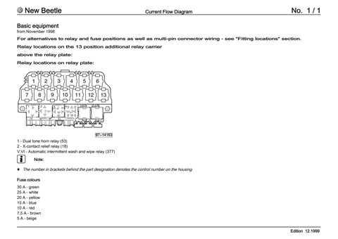
Relay locations on the 13 position additional relay carrier above the relay plate:
Relay locations on relay plate:
1 - Dual tone horn relay (53)
2 - X-contact relief relay (18) V,VI - Automatic intermittent wash and wipe relay (377)

Note:
Thenumberinbracketsbehindthepartdesignationdenotesthecontrolnumberonthehousing.
CLICK HERE TO DOWNLOAD THE COMPLETE MANUAL
• Thank you very much for reading the preview of the manual.
• You can download the complete manual from: www.heydownloads.com by clicking the link below

• Please note: If there is no response to CLICKING the link, please download this PDF first and then click on it.
CLICK HERE TO DOWNLOAD THE
New Beetle Current Flow Diagram
Battery, ignition/starter switch, X-contact relief relay
A Battery
B Starter
D Ignition/starter switch
J59 X-contact relief relay
S162 Fuse 1 (30), in fuse holder on battery
S163 Fuse 2 (30), in fuse holder on battery
S164 Fuse 3 (30), in fuse holder on battery
S176 Fuse 4 (30), in fuse holder on battery
S177 Fuse 5 (30), in fuse holder on battery
S178 Fuse 6 (30), in fuse holder on battery
S179 Fuse 7 (30), in fuse holder on battery
S180 Fuse 8 (30), in fuse holder on battery
T3 3-pin connector
T6 6-pin connector, brown, in connector protective housing, on left in plenum chamber

1 Earth strap, battery - body
2 Earth strap, gearbox - body
500 Screw connection 1 (30), on relay plate
501 Screw connection 2 (30), on relay plate
503 Screw connection (75x), on relay plate A2 Positive connection (15), in dash panel wiring harness
(30),
(30), in dash panel
Connection 1 (X), in dash panel wiring
New Beetle Current Flow Diagram
Dash panel insert, immobilizer
C Alternator
D2 Immobilizer reader coil
H16 Lights switched on warning buzzer
J285 Control unit with display in dash panel insert
J362 Immobilizer control unit
J... Engine control units
K2 Alternator warning lamp
K117 Immobilizer warning lamp
S5 Fuse 5 in fuse holder
S7 Fuse 7 in fuse holder
S11 Fuse 11 in fuse holder
T4g 4-pin connector, in engine compartment, near starter
T6 6-pin connector, brown, in connector protective housing, on left in plenum chamber
T10 10-pinconnector,orange,inconnectorprotectivehousing,on left in plenum chamber
T32 32-pin connector, blue
T32a 32-pin connector, green
42 Earth point, next to steering column
81 Earth connection 1, in dash panel wiring harness
A2 Positive connection (15), in dash panel wiring harness
A13 Connection (door contact switch), in dash panel wiring harness
New Beetle Current Flow Diagram
Dash panel insert, rev. counter, odometer display
G5 Rev. counter
G22 Speedometer sender, in gearbox
J285 Control unit with display in dash panel insert
J... Engine control units
K105 Reserve fuel warning lamp
L75 Digital display illumination bulb
S22 Fuse 22 in fuse holder
S223 Fuse 23 in fuse holder
T10 10-pinconnector,orange,inconnectorprotectivehousing,on left in plenum chamber
T10a 10-pinconnector,incablechannelleftinenginecompartment
T14 14-pin connector, in engine compartment
T32 32-pin connector, blue
T32a 32-pin connector, green
Y4 Odometer display
A27 Connection (speed signal), in dash panel wiring harness
A43 Connection (57L), in dash panel wiring harness
A44 Connection (57R), in dash panel wiring harness
A84 Connection (58L), in dash panel wiring harness
A85 Connection (58R), in dash panel wiring harness
* revolution signal engine control unit
New Beetle Current Flow Diagram
Dash panel insert, handbrake warning, brake fluid level warning contact, turn signal warning lamps, main beam warning lamp, rear fog light warning lamp
F9 Handbrake warning switch
F34 Brake fluid level warning contact
J285 Control unit with display in dash panel insert
K1 Main beam warning lamp
K13 Rear fog light warning lamp
K14 Handbrake warning lamp
K65 Left turn signal warning lamp
K94 Right turn signal warning lamp
K118 Brake system warning lamp
T32 32-pin connector, blue
T32a 32-pin connector, green
Y2 Digital clock
Earth connection 1, in dash panel wiring harness
Earth connection 2, in dash panel wiring harness 179 Earth connection, in left headlight wiring harness
Earth connection 1, in interior wiring harness 605 Earth point, on top end of steering column A5 Positive connection (right turn signal), in dash panel wiring harness A6 Positive connection (left turn signal), in dash panel wiring harness
A51 Connection (56), in dash panel wiring harness
A88 Connection (RFL), in dash panel wiring harness
not for ABS
New Beetle Current Flow Diagram
Turn signal switch, headlight dipper/flasher switch, parking light switch, front left bulbs
E2 Turn signal switch
E4 Headlight dipper/flasher switch
E19 Parking light switch
L1 Left twin filament bulb
M1 Left side light bulb
M5 Front left turn signal bulb
M18 Left side mounted turn signal bulb
S18 Fuse 18 in fuse holder
S19 Fuse 19 in fuse holder
S21 Fuse 21 in fuse holder
T8l 10-pin connector, on left headlight
T12 12-pin connector
12 Earth point, on left in engine compartment
179 Earth connection, in left headlight wiring harness
B166 Connection (56a), in interior wiring harness
B167 Connection (56b), in interior wiring harness
New Beetle Current Flow Diagram
Hazard warning light switch, turn signal relay, front right bulbs
E3 Hazard warning light switch
J1 Turn signal relay
K6 Hazard warning light system warning lamp
L2 Right twin filament bulb
M3 Right side light bulb
M7 Front right turn signal bulb
M19 Right side mounted turn signal bulb
S20 Fuse 20 in fuse holder
T7e 7-pin connector
T8l 8-pin connector
12 Earth point, on left in engine compartment
42 Earth point, next to steering column
81 Earth connection 1, in dash panel wiring harness
179 Earth connection, in left headlight wiring harness
B167 Connection (56b), in interior wiring harness
C28 Connection 1 (56b), in headlight wiring harness
New Beetle Current Flow Diagram
Brakelightswitch,brakelight,rearfoglight,leftreversing light, left tail light
F Brake light switch
F4 Reversing light switch
F47 Diesel direct injection system brake light switch
J248 Diesel direct injection system control unit
L46 Rear left fog light bulb
M6 Rear left turn signal bulb
M16 Left reversing light bulb
M21 Left brake and tail light bulb
M25 High level brake light bulb (32 LED's)
T5 5-pin connector, black, coupling station on left C-pillar
T10 10-pinconnector,orange,inconnectorprotectivehousing,on left in plenum chamber
50 Earth point, on left in luggage compartment
98 Earth connection, in rear lid wiring harness
199 Earth connection 3, in rear lid dash panel wiring harness
A6 Positive connection (left turn signal), in dash panel wiring harness
A18 Connection (54), in dash panel wiring harness
B146 Positive connection 1 (87), in interior wiring harness
W3 Connection, in rear wiring harness only models with diesel engine
New Beetle
Right tail light, brake light, right reversing light, tank filler flap remote release switch
E204 Tank filler flap remote release switch
L76 Button illumination bulb
M8 Rear right turn signal bulb
M17 Right reversing light bulb
M22 Right brake and tail light bulb
S14 Fuse 14 in fuse holder
S238 Fuse 38 in fuse holder
T5a 5-pin connector, black
T10i 10-pin connector
V155 Tank filler flap locking motor 98 Earth connection, in rear lid wiring harness
Earth connection 2, in dash panel wiring harness
Earth connection 3, in dash panel wiring harness
205 Earth connection, in driver door wiring harness
218 Earth connection -1-, in rear lid wiring harness
A5 Positive connection (right turn signal), in dash panel wiring harness
A66 Positive connection (30a, CL/ATA/IR), in dash panel wiring harness
R37 Connection 1 (window regulator), in driver door wiring harness
CLICK HERE TO DOWNLOAD THE COMPLETE MANUAL
• Thank you very much for reading the preview of the manual.
• You can download the complete manual from: www.heydownloads.com by clicking the link below
• Please note: If there is no response to CLICKING the link, please download this PDF first and then click on it.
CLICK HERE TO DOWNLOAD THE
New Beetle Current Flow Diagram
Connection for radio, front and rear cigarette lighter, socket
L28 Cigarette lighter illumination bulb
L32 Rear cigarette lighter illumination bulb
L42 Socket illumination bulb
R Radio
S15 Fuse 15 in fuse holder
S237 Fuse 37 in fuse holder
S239 Fuse 39 in fuse holder
S240 Fuse 40 in fuse holder
S241 Fuse 41 in fuse holder
S242 Fuse 42 in fuse holder
T8 8-pin connector, on radio
U Electric socket
U1 Cigarette lighter
U9 Rear cigarette lighter
Earth point, centre behind dash panel
Earth connection 1, in dash panel wiring
A1 Positive connection (30a), in dash panel wiring harness
A4 Positive connection (58b), in dash panel wiring harness
A21 Connection (86s), in dash panel wiring harness
A23 Positive connection (30al), in dash panel wiring harness
New Beetle
Light switch, rear fog light switch, ashtray illumination bulb
E1 Light switch
E18 Rear fog light switch
L9 Light switch illumination bulb
L15 Ashtray illumination bulb
S36 Fuse 36 in fuse holder
T18 18-pin connector
50 Earth point, on left in luggage compartment
New Beetle Current Flow Diagram
Dual tone horn, glove compartment light, number plate light
E26 Glove compartment light switch
H Horn plate
H1 Dual tone horn
J4 Dual tone horn relay
S3 Fuse 3 in fuse holder
S4 Fuse 4 in fuse holder
T2 2-pin connector, on left in luggage compartment
T5b 5-pin connector, next to steering column
W6 Glove compartment light
X Number plate lights
81 Earth connection 1, in dash panel wiring harness
Earth connection, in left headlight wiring harness
Earth connection 3, in dash panel wiring harness 218 Earth connection -1-, in rear lid wiring harness
A90 Connection (dual tone horn), in dash panel wiring harness
W11 Connection (58), in rear lid wiring harness
New Beetle Current Flow Diagram
Headlight range control regulator, headlight range control motor, illumination regulators - switches and instruments
E20 Illumination regulators - switches and instruments
E102 Headlight range control regulator
L54 Headlight range control regulator illumination bulb
T6c 6-pin connector
T8l 8-pin connector, on left headlight
T8r 8-pin connector, on right headlight
V48 Left headlight range control motor
V49 Right headlight range control motor
42 Earth point, on steering column
A103 Connection 2 (56), in dash panel wiring harness
A114 Connection (headlight range control), in dash panel wiring harness
A11 Connection 2 (58b), in dash panel wiring harness
119 Earth connection 1, in headlight wiring harness
New Beetle Current Flow Diagram
Fresh air blower switch, fresh air/air recirculation flap switch, fresh air blower, fresh air/recirculated air flap control motor
E9 Fresh air blower switch
E159 Fresh air/air recirculation flap switch
K114 Fresh air and air recirculation warning lamp
L16 Fresh air regulator illumination bulb
N24 Fresh air blower series resistor with overheating fuse
S2 Fuse 2 in fuse holder
S225 Fuse 25 in fuse holder
T4c 4-pin connector
T6d 6-pin connector
T8b 8-pin connector
T10j 10-pin connector, behind centre dash panel
V2 Fresh air blower
V154 Fresh air/recirculated air flap control motor
44 Earth point, lower part of left A-pillar
162 Earth connection, in blower motor wiring harness
A1 Positive connection (30a), in dash panel wiring harness
A20 Connection (15a), in dash panel wiring harness
L66 Connection, in heater blower wiring harness
New Beetle
= brown
= green
Heated rear window, heated exterior mirror, washer pump
E15 Heated rear window switch
K10 Heated rear window warning lamp
L39 Heated rear window switch illumination bulb
S224 Fuse 24 in fuse holder
S226 Fuse 26 in fuse holder
T5 5-pin connector, black, coupling station on left C-pillar
T7 7-pin connector
V5 Washer pump
Z1 Heated rear window
Z4 Driver side heated exterior mirror
Z5 Front passenger heated exterior mirror
81 Earth connection 1, in dash panel wiring harness
98 Earth connection, in rear lid wiring harness
A82 Connection (windscreen heater), in dash panel wiring harness
A96 Connection (53a), in dash panel wiring harness
A97 Connection (53), in dash panel wiring harness
A102 Connection(windscreenwiper),indashpanelwiringharness
New Beetle Current Flow Diagram
Intermittent wiper switch, windscreen wiper motor
E22 Intermittent wiper switch
E38 Intermittent wiper regulator
J31 Automatic intermittent wash and wipe relay, on relay plate
T5c 5-pin connector, on windscreen wiper motor
T6d 6-pin connector
T8c 8-pin connector
T18a 18-pin connector
V Windscreen wiper motor
81 Earth connection 1, in dash panel wiring harness
179 Earth connection, in left headlight wiring harness
A96 Connection (53a), in dash panel wiring harness
A97 Connection (53), in dash panel wiring harness
A102 Connection(windscreenwiper),indashpanelwiringharness
New Beetle Current Flow Diagram
Front interior light, digital clock, ambient temperature sensor, left door warning lamp
F2 Driver door contact switch
G17 Ambient temperature sensor
J29 Blocking diode
M27 Left door warning lamp
T10i 10-pin connector, black, coupling station on left A-pillar
W Front interior light
Y2 Digital clock
New Beetle
Rear right and left reading light, right door warning lamp, right door contact switch
F3 Front passenger door contact switch
F5 Luggage compartment light switch
J29 Blocking diode
M28 Right door warning lamp
T5 5-pin connector, black
T5b 5-pin connector, brown
T10r 10-pin connector, black, coupling station right A-pillar
W3 Luggage compartment light
W11 Rear left reading light
W12 Rear right reading light
Connection (interior
Connection 2, in
R6 Positive connection 1, in interior light wiring harness
R7 Positive connection 2, in interior light wiring harness
R48 Connection, in front passenger side door wiring harness
CLICK HERE TO DOWNLOAD THE COMPLETE MANUAL
• Thank you very much for reading the preview of the manual.
• You can download the complete manual from: www.heydownloads.com by clicking the link below
• Please note: If there is no response to CLICKING the link, please download this PDF first and then click on it.
CLICK HERE TO DOWNLOAD THE
New Beetle Current Flow Diagram
Self-diagnosis connection
J...
2.0 ltr./85 kW Motronic, engine code AQY
From November 1998
For alternatives to relay and fuse positions as well as multi-pin connector wiring - see "Fitting locations section"
Relay locations on 13 position additional
relay carrier, above relay plate:
Relay locations on relay plate:
2 - X contact relief relay (213)
4 - Fuel pump relay (409)
Note:
Thenumberinbracketsbehindthepartdesignationdenotesthecontrolnumberonthehousing.
New Beetle
= white
= black
= red
= brown
= green
blue
grey
= purple
= yellow
= orange rs = pink
Alternator, starter
A Battery
B Starter
C Alternator
C1 Voltage regulator
D Ignition/starter switch
E1 Lighting switch
J59 X contact relief relay
S162 Fuse -1- (30), in battery fuse holder
S163 Fuse -2- (30), in battery fuse holder
S176 Fuse -4- (30), in battery fuse holder
S177 Fuse -5- (30), in battery fuse holder
T4 4-pin connector, near starter
T6 6-pin connector, brown, in protective housing for connectors, left in plenum chamber
500 Screw connection -1- (30), on relay plate
501 Screw connection -2- (30), on relay plate
502 Screw connection -1- (30a), on relay plate
A41 Positive (+) connection (50), in dash panel wiring harness
A32 Positive connection (30), in dash panel wiring harness
New Beetle
Motronic control unit, ignition system
D Ignition/starter switch
J220 Motronic control unit, centre in plenum chamber
N152 Ignition transformer
P Spark plug connector
Q Flame plug
S10 Fuse in relay plate fuse box
S229 Fuse in fuse holder
T4a 4-pin connector
T6 6-pin connector, brown
T14 14-pin connector, in engine compartment
T80 80-pin connector
Earth point, in plenum chamber
New Beetle Current Flow Diagram
Motronic control unit, throttle valve control unit, coolant temperature sender
F60 Idling switch
G2 Coolant temperature sender
G40 Hall sender
G62 Coolant temperature sender
G69 Throttle valve potentiometer
G88 Throttle valve positioner potentiometer
J220 Motronic control unit, centre in plenum chamber
J338 Throttle valve control unit
T8 8-pin connector
T14 14-pin connector, left in plenum chamber
T80 80-pin connector
V60 Throttle valve positioner
220 Earth connection (sender earth), in engine wiring harness
D147 Connection(rearleftspeedsensor-),inenginecompartment wiring harness
New Beetle Current Flow Diagram No.
Motroniccontrolunit,enginespeedsender,knocksensor I, knock sensor II
G28 Engine speed sender
G61 Knock sensor I
G66 Knock sensor II
J217 Automatic gearbox, in plenum chamber, centre
J220 Motronic control unit, in plenum chamber, centre
T3a 3-pin connector, near intake manifold
T3b 3-pin connector, near intake manifold
T3c 3-pin connector, near intake manifold
T10 10-pinconnector,orange,connectorpoint,electronicsbox,in plenum chamber, left
T10a 10-pin connector, grey, connector point, electronics box, in plenum chamber, left
T10b 10-pin connector, blue, connector point, electronics box, in plenum chamber, left
T68 68-pin connector, on automatic gearbox control unit
T80 80-pin connector
220 Earth connection (sender earth), in engine wiring harness
* Compressor switch-off
** Air conditioner 'ready' connection
Only models with automatic gearbox
New Beetle Current Flow Diagram
Motronic control unit, injectors, lambda probe II, heater element
J220 Motronic control unit, in plenum chamber, centre
G108 Lambda probe II
N30 Injector, cylinder 1
N31 Injector, cylinder 2
N32 Injector, cylinder 3
N33 Injector, cylinder 4
N79 Heater element (crankcase breather)
T4 4-pin connector, in protective housing in engine compartment, rear
T6 6-pin connector, brown, connector point, electronics box, in plenum chamber, left
T10 10-pin connector, orange, connector point, electronics box, in plenum chamber, left
T10a 10-pin connector, grey, connector point, electronics box, in plenum chamber, left
T14 14-pin connector, in engine compartment
T16 16-pin connector, diagnostic connector
T80 80-pin connector
85 Earth connection -1-, in engine compartment wiring harness
A76 Connection (diagnosis wire K), in dash panel wiring harness
D140 Connection (injectors), in engine prewiring wiring harness
E30 Connection (87a), in engine wiring harness
New Beetle Current Flow Diagram
Motronic control unit, air mass meter, activated charcoal filter system solenoid valve, Lambda probe I, secondary air pump relay, secondary air pump motor
G39 Lambda probe
G70 Air mass meter
J220 Motronic control unit, centre in plenum chamber
J229 Secondary air pump relay
N80 Activated charcoal filter system solenoid valve I
T4b 4-pin connector
T80 80-pin connector
V101 Secondary air pump motor
10 Earth point, in plenum chamber
E30 Connection (87a), in engine wiring harness
New Beetle Current Flow Diagram
Oilpressureswitch,fuelpump,secondaryairinletvalve, coolantshortageindicatorsender,fuelsystemdiagnosis pump
J220 Motronic control unit, centre in plenum chamber
N112 Secondary air inlet valve (01235-4313)
G32 Coolant shortage indicator sender
S232 Fuse in fuse holder
S234 Fuse in fuse holder
S242 Fuse in fuse holder
T6 6-pin connector, brown, in engine compartment
T10 10-pin connector, orange, in engine compartment
T10a 10-pin connector, in cable channel left in engine compartment
T80 80-pin connector
V144 Fuel system diagnostic pump
A27 Connection (speed signal), in dash panel wiring harness
A101 Connection -3- (87), in dash panel wiring harness
B146 Connection -1- (87), in interior wiring harness
B147 Connection -2- (87), in interior wiring harness
E30 Connection (87a), in engine wiring harness
CLICK HERE TO DOWNLOAD THE COMPLETE MANUAL
• Thank you very much for reading the preview of the manual.
• You can download the complete manual from: www.heydownloads.com by clicking the link below
• Please note: If there is no response to CLICKING the link, please download this PDF first and then click on it.
CLICK HERE TO DOWNLOAD THE
New Beetle Current Flow Diagram
Fuel gauge sender, fuel pump (lift pump), speedometer sender, fuel pump relay, coolant shortage indicator sender
G Fuel gauge sender (00771-3113)
G6 Fuel pump (pre-supply pump)
G22 Speedometer sender (Hall sender on gearbox)
J17 Fuel pump relay (01259-4433)
G32 Coolant shortage indicator sender
J234 Airbag control unit
S228 Fuse in fuse holder
T14 14-pin connector, in engine compartment
T50 50-pin connector, on airbag control unit
Earth connection (sender earth) -1-, in dash panel
Earth connection -1-, in engine prewiring wiring harness
Screw connection -1- (87), on relay plate
A13 Connection (door contact switch), in dash panel wiring harness A101 Connection -3- (87), in dash panel wiring harness
(crash
New Beetle Current Flow Diagram
ws = white sw = black ro = red
= brown
= green
= blue
= grey
= purple ge = yellow
= orange rs = pink
Dash panel insert, rev. counter, optic and acoustic oil pressure warning, coolant temperature gauge, fuel gauge, alternator warning lamp, oil pressure switch
F1 Oil pressure switch
G1 Fuel gauge
G3 Coolant temperature gauge
G5 Rev. counter
H11 Oil pressure warning buzzer
J285 Control unit with display in dash panel insert
K2 Alternator warning lamp
K3 Oil pressure warning lamp
K83 Exhaust emissions warning lamp
T14 14-pin connector, in engine compartment
T32 32-pin connector, blue
T32a 32-pin connector, green
A27 Connection (speed signal), in dash panel wiring harness
1.9 ltr./66 kW Turbo diesel engine, engine code ALH
From November 1998
For alternatives to relay and fuse positions as well as multi-pin connector wiring - see "Fitting locations section"
Relay locations on 13 position additional
relay carrier, above relay plate:
Relay locations on relay plate:
2 - X contact relief relay (18)
10 - Glow plugs relay (103)
Note:
Thenumberinbracketsbehindthepartdesignationdenotesthecontrolnumberonthehousing.
New Beetle Current Flow Diagram
Alternator, starter
A Battery
B Starter
C Alternator
C1 Voltage regulator
D Ignition/starter switch
E1 Lighting switch
S11 Fuse in fuse box
S162 Fuse -1- (30), in battery fuse holder
S163 Fuse -2- (30), in battery fuse holder
S176 Fuse -4- (30), in battery fuse holder
S177 Fuse -5- (30), in battery fuse holder
S229 Fuse in fuse holder
T4g 4-pin connector, near starter
T6 6-pin connector, brown, in protective housing for connectors, left in plenum chamber
T18 18-pin connector, on lighting switch
500 Screw connection -1- (30), on relay plate
501 Screw connection -2- (30), on relay plate
A2 Positive (+) connection (15), in dash panel wiring harness
A32 Positive connection (30), in dash panel wiring harness
A52 Positive connection -2- (30), in dash panel wiring harness
New Beetle Current Flow Diagram
Diesel direct injection system control unit, kick-down switch, idling switch, accelerator pedal position sender, engine glow plugs
F8 Kick-down switch
F60 Idling switch
G79 Accelerator position sender
J52 Glow plug relay
J248 Diesel direct injection system control unit, centre in plenum chamber
Q6 Glow plugs - (engine)
T2 2-pin connector
T6 6-pinconnector,brown,inprotectivehousingforconnectors, left in plenum chamber
T6a 6-pin connector, behind dash panel wiring harness, left
T10 10-pin connector, orange, in protective housing for connectors, left in plenum chamber
T10h 10-pin connector, blue, in protective housing for connectors, left in plenum chamber
T14a 14-pin connector, black, in engine compartment
T80 80-pin connector
220 Earth connection (sender earth), in engine wiring harness
238 Earth connection -1-, in interior wiring harness
A104 Positive connection -2- (15), in dash panel wiring harness
New Beetle Current Flow Diagram
= red
= brown
= green
blue
Diesel direct injection system control unit, coolant temperature sender, air mass meter, intake manifold pressure sender, intake manifold temperature sender, engine speed sender
G2 Coolant temperature gauge sender
G28 Engine speed sender
G62 Coolant temperature sender
G70 Air mass meter
G71 Intake manifold pressure sender
G72 Intake manifold temperature sender
J217 Automatic gearbox control unit, centre in plenum chamber
J248 Diesel direct injection system control unit, centre in plenum chamber
T3 3-pin connector, on front of engine
T10 10-pin connector, orange, in protective housing for connectors, left in plenum chamber
T10d 10-pin connector, in engine compartment
T10e 10-pin connector, black, in engine compartment
T10h 10-pin connector, blue, in engine compartment
T14a 14-pin connector, in engine compartment
T68 68-pin connector
T80 80-pin connector
200 Earth connection (screening), in engine compartment wiring harness
220 Earth connection (sender earth), in engine wiring harness
* Compressor switch-off
** Air conditioner 'ready' connection For vehicles with automatic gearbox only
New Beetle Current Flow Diagram
brown
grey
purple
yellow
orange
= pink
Diesel direct injection system control unit, needle lift sender, fuel temperature sender, modulating piston movement sender, metering adjuster
G80 Needle lift sender
G81 Fuel temperature sender
G149 Modulating piston movement sender
J104 ABS/ABS with EDL control unit, in engine compartment, left
J217 Automatic gearbox, in plenum chamber, centre
J248 Diesel direct injection system control unit, in plenum chamber, centre
N146 Metering adjuster
T2a 2-pin connector, on engine front
T10a 10-pin connector, grey, connector point, electronics box, in plenum chamber, left
T10f 10-pin connector, on engine front
T14a 14-pin connector, black, in engine compartment
T25 25-pin connector
T68 68-pin connector
T80 80-pin connector
200 Earth connection (sender earth), in engine wiring harness
B229 Connection (high bus), in interior wiring harness
B230 Connection (low bus), in interior wiring harness
F25 Connection -1-, in diesel direct injection system wiring harness
* Only models with manual gearbox and heated pin heating
New Beetle
Diesel direct injection system control unit, intake manifold flap change-over valve, exhaust gas
recirculation valve, charge pressure control solenoid valve, commencement of injection valve, voltage supply relay
J248 Diesel direct injection system control unit, in plenum chamber, centre
J317 Terminal 30 voltage supply relay
N18 Exhaust gas recirculation valve
N75 Charge pressure control solenoid valve
N108 Commencement of injection valve
N109 Fuel shut-off valve
N239 Intake manifold flap change-over valve
S234 Fuse in fuse box
T6 6-pin connector, brown, connector point, electronics box, in plenum chamber, left
T10 10-pin connector, orange, connector point, electronics box, in plenum chamber, left
T10f 10-pin connector, on engine front
T10h 10-pin connector, blue, connector point, electronics box, in plenum chamber, left
T14a 14-pin connector, black, in engine compartment
T80 80-pin connector
B147 Positive (+) connection -2- (87), in interior wiring harness
E30 Connection (87a), in engine wiring harness
New Beetle Current Flow Diagram
Diesel direct injection system control unit, cruise control system switch (CCS), clutch pedal switch, brake light switch, brake pedal switch
E45 Cruise control system switch**
E227 Cruise control system (CCS) button (Set)**
F Brake light switch
F36 Clutch pedal switch
F47 Cruise cont. sys. brake pedal switch
J248 Diesel direct injection system control unit, centre in plenum chamber
S13 Fuse in relay plate fuse box
T7 7-pin connector, next to steering column
T10d 10-pin connector, green, in protective housing for connectors, left in plenum chamber
T10e 10-pinconnector,black,inprotectivehousingforconnectors, left in plenum chamber
T80 80-pin connector
A18 Connection (54), in dash panel wiring harness
A80 Connection -1- (X), in dash panel wiring harness
B146 Positive connection -1- (87), in interior wiring harness
* For vehicles with manual gearbox only
** For vehicles with cruise control system (CCS) only
CLICK HERE TO DOWNLOAD THE COMPLETE MANUAL
• Thank you very much for reading the preview of the manual.
• You can download the complete manual from: www.heydownloads.com by clicking the link below
• Please note: If there is no response to CLICKING the link, please download this PDF first and then click on it.
CLICK HERE TO DOWNLOAD THE
New Beetle Current Flow Diagram
Diesel direct injection system control unit, coolant heater elements
J248 Diesel direct injection system control unit, centre in plenum chamber
J359 Low heat output relay, in protective housing left in engine compartment, control number(53)*
J360 High heat output relay, in protective housing left in engine compartment, control number(53)*
Q7 Coolant heating elements*
T6 6-pin connector, brown, in protective housing for connectors, left in plenum chamber
T10 10-pin connector, orange, in protective housing for connectors, left in plenum chamber
T80 80-pin connector
10 Earth point, in plenum chamber
156 Earth connection, in diesel direct injection system wiring harness
A27 Connection (speed signal), in dash panel wiring harness
D50 Positive connection (30), in engine compartment wiring harness
D74 Connection (86), in engine compartment wiring harness
D98 Connection (glow plugs), in engine compartment wiring harness
* For vehicles with manual gearbox only
New Beetle
Fuel gauge sender, coolant shortage indicator sender
G Fuel gauge sender
G32 Coolant shortage indicator sender
S5 Fuse in fuse box
S232 Fuse in fuse holder
S243 Fuse in fuse holder
T6 6-pinconnector,brown,inprotectivehousingforconnectors, left in plenum chamber
T14a 14-pin connector, black, in engine compartment
269 Earth connection (sender earth) -1-, in dash panel wiring harness
A20 Connection (15a), in dash panel wiring harness
A99 Connection -1- (87), in dash panel wiring harness
A100 Connection -2- (87), in dash panel wiring harness
B147 Positive connection -2- (87), in interior wiring harness
New Beetle
ws = white
= black
= red
= brown
= green
blue
= grey
= purple
Dash panel insert, optical and acoustic oil pressure warning, speedometer sender, glow period warning lamp, coolant temperature/coolant shortage warning lamp
F1 Oil pressure switch
G22 Speedometer sender (Hall sender on gearbox)
H11 Oil pressure warning buzzer
J285 Control unit with display in dash panel insert
K2 Alternator warning lamp
K3 Oil pressure warning lamp
K28 Coolant temperature/coolant shortage warning lamp
K29 Glow period warning lamp
T14a 14-pin connector, black, in engine compartment
T32 32-pin connector, blue
T32a 32-pin connector, green
= pink
179 Earth connection, in left headlight wiring harness
New Beetle Current Flow Diagram
Dash panel insert, coolant temperature gauge, fuel gauge, rev. counter
G1 Fuel gauge
G3 Coolant temperature gauge
G5 Rev. counter
J285 Control unit with display in dash panel insert
K105 Reserve fuel warning lamp
T32 32-pin connector, blue
A27 Connection (speed signal), in dash panel wiring harness
* Speed signal from engine control unit
New Beetle
Radio systems
From November 1998
For alternatives to relay and fuse positions as well as multi-pin connector wiring - see "Fitting locations section"
New Beetle
Radio, CD changer, front loudspeakers
R Radio
R20 Treble loudspeaker, front left, in door
R21 Bass loudspeaker, front left, in door
R41 CD changer, rear left in luggage compartment
T8a 8-pin connector
T10i 10-pin connector, black, left A pillar coupling station
T12 12-pin connector
T20 20-pin connector
45 Earth point, behind dash panel - centre
255 Earth connection -1-, in radio wiring harness
V14 Connection (screening), in CD changer wiring harness
New Beetle
purple ge = yellow
orange rs = pink
Radio, front loudspeakers, rear loudspeakers
R Radio
R4 Loudspeaker, rear left
R5 Loudspeaker, rear right
R22 Treble loudspeaker, front right, in door
R23 Bass loudspeaker, front right, in door
T8a 8-pin connector
T10r 10-pin connector, black, on radio
New Beetle Current Flow Diagram
Radio, aerial
D Ignition/starter switch
E20 Switches and instruments - lighting control
J285 Control unit with display in dash panel insert
R Radio
R11 Aerial
R24 Aerial amplifier
S237 Fuse in fuse holder
S242 Fuse in fuse holder
T1 Single connector, near roof aerial
T6c 6-pin connector
T8 8-pin connector
T16 16-pin connector, in centre of dash panel, self-diagnosis connection
T32 32-pin connector, blue
T32a 32-pin connector, green
Earth point, behind dash panel - centre
Earth connection -1-, in radio wiring harness 501 Screw connection -2- (30), on relay plate
A4 Positive (+) connection (58b), in dash panel wiring harness
A21 Connection (86s), in dash panel wiring harness
A23 Connection (30a), in dash panel wiring harness
A76 Connection (diagnosis wire K), in dash panel wiring harness
* Not with CD changer
New Beetle
4 Speed automatic gearbox (AG 4)
From November 1998
For alternatives to relay and fuse positions as well as multi-pin connector wiring - see "Fitting locations section"
Relay locations on 13 position additional
relay carrier, above relay plate:
97--14163
11 - Relay for starter inhibitor and reversing light (175)
Note:
♦ Thenumberinbracketsbehindthepartdesignationdenotesthecontrolnumberonthehousing.
CLICK HERE TO DOWNLOAD THE COMPLETE MANUAL
• Thank you very much for reading the preview of the manual.
• You can download the complete manual from: www.heydownloads.com by clicking the link below
• Please note: If there is no response to CLICKING the link, please download this PDF first and then click on it.
CLICK HERE TO DOWNLOAD THE
New Beetle Current Flow Diagram
Starter inhibitor and reversing light relay
B Starter
D Ignition/starter switch
F4 Reversing light switch
J226 Starter inhibitor and reversing light relay, on 13 position additional relay carrier
J285 Control unit with display in dash panel insert
S15 Fuse in relay plate fuse box
T6 6-pin connector, brown, in protective housing for connectors, left in plenum chamber
T10 10-pin connector, orange, in protective housing for connectors, left in plenum chamber
T10g 10-pin connector, grey, in protective housing for connectors, in plenum chamber, left
T32 32-pin connector, blue
114 Earth connection (dash panel insert), in automatic gearbox wiring harness
501 Screw connection -2- (30), on relay plate
A32 Positive connection (30), in dash panel wiring harness
A52 Positive connection -2- (30), in dash panel wiring harness
A56 Positive connection -2- (30), in dash panel wiring harness
A87 Connection (RL), in dash panel wiring harness
New Beetle Current Flow Diagram
Automatic gearbox control unit, multi-function switch, kick-down switch
F Brake light switch
F8 Kick-down switch
F125 Multi-function switch
J... Engine control unit, in plenum chamber, centre
J217 Automatic gearbox, in plenum chamber, centre
J285 Control unit with display in dash panel insert
T8 8-pin connector
T10 10-pin connector, orange, in protective housing for connectors, in plenum chamber, left
T10g 10-pinconnector,grey,inprotectivehousingforconnectors, in plenum chamber, left
T16 16-pin connector, in dash panel centre, self-diagnosis connection
T32 32-pin connector, blue
T68 68-pin connector
10 Earth point, in plenum chamber
114 Earth connection, in automatic gearbox wiring harness
A18 Connection (54), in dash panel wiring harness
A56 Positive (+) connection -2- (30), in instruments wiring harness
A76 Connection (diagnosis wire K), in dash panel wiring harness
* Compressor switch-off
New Beetle Current Flow Diagram
Automatic gearbox control unit, solenoid valve, gearbox speed sender
G38 Gearbox speed sender
G93 Gearbox oil temperature sender
J... Engine control unit, in plenum chamber, centre
J104 ABS/ABS with EDL control unit
J217 Automatic gearbox Gearbox, in plenum chamber, centre
N88 Solenoid valve 1
N89 Solenoid valve 2
N90 Solenoid valve 3
N91 Solenoid valve 4
N92 Solenoid valve 5
N93 Solenoid valve 6
N94 Solenoid valve 7
T2 2-pin connector, on gearbox
T10a 10-pin connector, green, in protective housing for connectors, in plenum chamber, left
T12 12-pin connector
T25 25-pin connector
T68 68-pin connector
B229 Connection (high bus), in interior wiring harness
B230 Connection (low bus), in interior wiring harness
New Beetle Current Flow Diagram
Automatic gearbox control unit, road speed sender, selector lever lock solenoid
E1 Lighting switch
G68 Road speed sender
J29 Diode
J217 Automatic gearbox control unit, centre in plenum chamber
J285 Control unit with display in dash panel insert
K142 Selector lever position P/N warning lamp
L101 Selector lever display illumination
N110 Selector lever lock solenoid
S7 Fuse in fuse box
S11 Fuse in fuse box
S231 Fuse in fuse holder
T3 3-pin connector, on gearbox
T10g 10-pin connector, grey, in protective housing for connectors, left plenum chamber
T32 32-pin connector, blue
T68 68-pin connector
238 Earth connection -1-, in interior wiring harness
A2 Positive (+) connection (15), in dash panel wiring harness
A4 Positive (+) connection (58b), in dash panel wiring harness
A53 Positive connection (58b), in dash panel wiring harness
B163 Positive connection -1- (15), in interior wiring harness
B165 Positive connection -2- (15), in interior wiring harness
U8 Positive connection (15a), in automatic gearbox wiring harness
New Beetle
Airbag system
⇒ Driver`s and front passenger`s airbag
⇒ Seat belt tensioner
⇒ Side airbags
From November 1998
For alternatives to relay and fuse positions as well as multi-pin connector wiring - see "Fitting locations section"
Relay locations on 13 position additional
relay carrier, above relay plate:
Relay locations on relay plate:
1 - Dual tone horn relay (53)
Note:
♦ Thenumberinbracketsbehindthepartdesignationdenotesthecontrolnumberonthehousing.
New Beetle Current Flow Diagram
= white
= black
= red
= brown
= green
= blue
= grey
= purple ge = yellow
= orange rs = pink
Airbag control unit, airbag coil connector, front airbag igniter, side airbag crash sensors
F138 Coil spring for airbag
G179 Side airbag crash sensor, driver`s side
G180 Side airbag crash sensor, front passenger`s side
H Horn plate
J4 Dual tone horn relay
J234 Airbag control unit, behind lower console
N95 Airbag igniter, driver side
N131 Airbag igniter 1, front passenger side
T5b 5-pin connector, next to steering column
T50 50-pin connector
81 Earth connection -1-, in dash panel wiring harness
109 Earth connection, in airbag wiring harness
New Beetle Current Flow Diagram
= brown
green
blue
grey
Airbag control unit, side airbag igniter, belt tensioner igniter
J234 Airbag control unit, behind lower console
N153 Belt tensioner igniter -1-, driver's side
N154 Belt tensioner igniter -2-, front passenger's side
N199 Side airbag igniter, driver`s side
N200 Side airbag igniter, front passenger's side
T2 2-pin connector, under driver's seat
T2a 2-pin connector, under driver's seat
T3 3-pin connector, under driver's seat
T3a 3-pin connector, under front passenger's seat
T50 50-pin connector 34 Earth point, under driver`s seat
35 Earth point, under front passenger seat
orange
135 Earth connection -2-, in dash panel wiring harness
* Protect wiring against static charging from seat
New Beetle Current Flow Diagram
ws = white sw = black ro = red br = brown gn = green bl = blue gr = grey li = purple ge = yellow or = orange rs = pink
Airbag control unit, airbag warning lamp
D Ignition/starter switch
J234 Airbag control unit, behind lower console
J285 Control unit with display in dash panel insert
J393 Conveniencesystemcentralcontrolunit,behinddashpanel,left
K75 Airbag warning lamp, in dash panel insert
T4 4-pin connector, behind dash panel, right (woven into wiring harness)
T16 16-pin connector, in centre of dash panel, self-diagnosis connection
T23 23-pin connector, on convenience system control unit
T32 32-pin connector, blue
T32a 32-pin connector, green
T50 50-pin connector
109 Earth connection, in airbag wiring harness
238 Earth connection -1-, in interior wiring harness
A2 Positive (+) connection (15), in dash panel wiring harness
A76 Connection (diagnosis wire K), in dash panel wiring harness
A125 Connection (crash signal), in dash panel wiring harness
CLICK HERE TO DOWNLOAD THE COMPLETE MANUAL
• Thank you very much for reading the preview of the manual.
• You can download the complete manual from: www.heydownloads.com by clicking the link below
• Please note: If there is no response to CLICKING the link, please download this PDF first and then click on it.
CLICK HERE TO DOWNLOAD THE
Cruise control system (CCS), for engine code AQY only
From November 1998
For alternatives to relay and fuse positions as well as multi-pin connector wiring - see "Fitting locations section"
Relay locations on 13 position additional
relay carrier, above relay plate:
Note: ♦ Thenumberinbracketsbehindthepartdesignationdenotesthecontrolnumberonthehousing.
New Beetle
Brake light switch, brake pedal switch for CCS
D Ignition/starter switch
F Brake light switch
F47 Cruise cont. sys. brake pedal switch
S5 Fuse in fuse box
S13 Fuse in relay plate fuse box
S234 Fuse in
(15),
A18 Connection (54), in dash panel wiring harness
A20 Connection (15a), in dash panel wiring harness
A80 Connection -1- (X), in dash panel wiring harness
A99 Connection -1- (87), in dash panel wiring harness
B146 Positive connection -1- (87), in interior wiring harness
* For vehicles with automatic gearbox only Not vehicles with automatic gearbox
New Beetle Current Flow
Motronic control unit, switch for cruise control system (CCS), clutch pedal switch
E45 Cruise control system switch
E227 Cruise control system (CCS) button (Set)
F36 Clutch pedal switch
J220 Motronic control unit, centre in plenum chamber
T10a 10pin connector, black, in protective housing, left in plenum chamber
T10e 10-pinconnector,black,inprotectivehousingforconnectors, left in plenum chamber
T10s 10-pin connector, next to steering column
T80 80-pin connector
A18 Connection (54), in dash panel wiring harness * For vehicles with automatic gearbox only
Not vehicles with automatic gearbox
New Beetle
T8/1T8/2T8/6T8/5T8/4
ws = white sw = black ro = red br = brown gn = green bl = blue
gr = grey
li = purple
ge = yellow
or = orange
rs = pink
Motronic control unit, throttle valve control part
F60 Idling switch
G40 Hall sender
G69 Throttle valve potentiometer
G88 Throttle valve positioner potentiometer
J220 Motronic control unit, centre in plenum chamber
J338 Throttle valve control unit
T8 8-pin connector
T80 80-pin connector
V60 Throttle valve positioner
220 Earth connection (sender earth), in engine wiring harness
D147 Connection (rear left speed sensor -), in engine compartment wiring harness
Anti-lock brake system (ABS), anti-lock brake system (ABS) with electronic differential lock (EDL), anti-lock brake system (ABS) with brake pad wear monitor
From November 1998
For alternatives to relay and fuse positions as well as multi-pin connector wiring - see "Fitting locations section"
New Beetle Current Flow Diagram
ABS for control unit, brake light switch
A Battery
F Brake light switch
F47 Cruise control system brake pedal switch (diesel direct injection system)
J104 ABS/ABS with EDL control unit, in engine compartment, left
J217 Automatic gearbox control unit
J... Engine control units
S13 Fuse in fuse box
S178 Fuse -6- (30), in fuse box/battery
S179 Fuse -7- (30), in fuse box/battery
T3 3-pin connector
T10d 10-pin connector, in protective housing for connectors, in plenum chamber, left
T14 14-pin connector, in engine compartment
T25 25-pin connector
T68 68-pin connector
501 Screw connection -2- (30), on relay plate
A18 Connection (54), in dash panel wiring harness
A81 Connection -2- (X), in dash panel wiring harness
B146 Positive (+) connection -1- (87), in interior wiring harness
B229 Connection (high bus), in interior wiring harness
B230 Connection (low bus), in interior wiring harness
<fo:exter nal-
graphic
src="/../ PDOC/ samba/ tools/ pngconvert/ out//slp/ ft_icons/ m_m_m. png" contentwidth="2 0pt" scaling=" uniform"/
> Only models with diesel engine
<fo:exter nalgraphic
src="/../
Only models with petrol engine
New Beetle Current Flow Diagram
ws = white
= black
= red
= brown
green
= blue gr = grey li = purple ge = yellow
= orange rs = pink
Control unit for ABS with EDL, ABS warning lamp, ABS hydraulic pump
D Ignition/starter switch
J104 ABS with EDL control unit, left in engine compartment
J285 Control unit with display in dash panel insert
K47 ABS warning lamp
N125 Differential lock valve 1*
N126 Differential lock valve 2*
N133 ABS inlet valve, rear right
N134 ABS inlet valve, rear left
N135 ABS outlet valve, rear right
N136 ABS outlet valve, rear left
S9 Fuse in relay plate fuse box
T2 2-pin connector
T16 16-pin connector, in centre of dash panel, self-diagnosis connection
T25 25-pin connector
T32 32-pin connector, blue
T32a 32-pin connector, green
V64 ABS hydraulic pump
12 Earth point, left in engine compartment 132 Earth connection -3-, in engine compartment wiring harness 238 Earth connection -1-, in interior wiring harness
A76 Connection (diagnosis wire K), in dash panel wiring harness
A80 Connection -1- (X), in dash panel wiring harness
D53 Connection, (brake wear indicator, right) in engine compartment wiring harness
* For vehicles electronic differential lock (EDL) only
New Beetle Current Flow Diagram
= white
= black
= red
= brown
= green
= blue
= grey
= purple
= yellow
= orange
= pink
ABS with EDL, speed sensor, brake pas wear sender
G34 Brake lining/pad wear sender, front left
G35 Brake lining/pad wear sender, front right
G44 Rear right speed sensor
G45 Front right speed sensor
G46 Rear left speed sensor
G47 Front left speed sensor
J104 ABS with EDL control unit, left in engine compartment
N99 ABS inlet valve, front right
N100 ABS outlet valve, front right
N101 ABS inlet valve, front left
N102 ABS outlet valve, front left
T2a 2-pin connector, near rear right speed sensor
T2b 2-pin connector, near rear left speed sensor
T25 25-pin connector
132 Earth connection -3-, in engine compartment wiring harness
D53 Connection,(brakewearindicator,right)inenginecompartment wiring harness
C5 Earth connection -1- (brake pad wear monitor) in front left wiring harness
C6 Earth connection -2- (brake pad wear monitor) in front left wiring harness
D146 Connection (rear left speed sensor +), in engine compartment wiring harness
D147 Connection (rear left speed sensor -), in engine compartment wiring harness
D148 Connection (rear right speed sensor +), in engine compartment wiring harness
D149 Connection (rear right speed sensor -), in engine compartment wiring harness
Flow Diagram
Anti-lock brake system (ABS) with electronic differential lock (EDL), traction control system (TCS) and electronic stability program (ESP)
From November 1998
For alternatives to relay and fuse positions as well as multi-pin connector wiring - see "Fitting locations section"
Relay locations on the 13 position additional relay carrier above the relay plate:
7 - Brake light suppression relay
Relay locations on relay plate:
Note:
♦ Thenumberinbracketsbehindthepartdesignationdenotesthecontrolnumberonthehousing.
CLICK HERE TO DOWNLOAD THE COMPLETE MANUAL
• Thank you very much for reading the preview of the manual.
• You can download the complete manual from: www.heydownloads.com by clicking the link below
• Please note: If there is no response to CLICKING the link, please download this PDF first and then click on it.
CLICK HERE TO DOWNLOAD THE
New Beetle Current Flow Diagram
ABS with EDL/TCS/ESP control unit, TCS/ESP button
A Battery
D Ignition/starter switch
E20 Switches and instruments, lighting control
E256 TCS/ESP button
J104 ABS with EDL/ TCS/ ESP control unit, in engine compartment, left
L71 Traction control switch illumination
S9 Fuse in fuse box
S178 Fuse -6- (30), in fuse box/battery
S179 Fuse -7- (30), in fuse box/battery
T3 3-pin connector
T6 6-pin connector
T6c 6-pin connector
T47 47-pin connector
45 Earth point, behind dash panel, centre
238 Earth connection -1-, in interior wiring harness
A2 Positive (+) connection (15), in dash panel wiring harness
A38 Positive (+) connection -2- (15a), in dash panel wiring harness
A116
Positive (+) connection -2- (58d), in dash panel wiring harness
A132 Connection (TCS/ESP), in dash panel wiring harness
New Beetle Current Flow Diagram
ABS with EDL/ TCS/ ESP control unit, steering angle sender, brake light suppression relay
G85 Steering angle sender, on steering column
J104 ABS with EDL/ TCS/ ESP control unit, in engine compartment, left
J217 Automatic gearbox, in plenum chamber, centre*
J... Engine control units
N133 ABS inlet valve, rear right
N134 ABS inlet valve, rear left
N135 ABS outlet valve, rear right
N136 ABS outlet valve, rear left
T6k 6-pin connector, on exhaust gas recirculation potentiometer
T10a 10-pin connector, grey, connector point, electronics box, in plenum chamber, left
T14a 14-pin connector, black, in engine compartment
T47 47-pin connector, ABS with EDL/TCS/ESP control unit
T68 68-pin connector, on automatic gearbox control unit control unit
238 Earth connection -1-, in interior wiring harness
B229 Connection (high bus), in interior wiring harness
B230 Connection (low bus), in interior wiring harness
* Only models with automatic gearbox Only models with diesel engine
New Beetle
= grey
= purple
= yellow
= orange
= pink
ABS with EDL/TCS/ESP control unit, speed sensors
G44 Rear right speed sensor
G45 Front right speed sensor
G46 Rear left speed sensor
G47 Front left speed sensor
J104 ABS with EDL/ TCS/ ESP control unit, in engine compartment, left
N99 ABS inlet valve, front right
N100 ABS outlet valve, front right
N101 ABS inlet valve, front left
N102 ABS outlet valve, front left
N227 Electronic stability program high pressure valve -1-
N228 Electronic stability program high pressure valve -2-
T2c 2-pin connector, near rear right speed sensor
T2d 2-pin connector, near rear left speed sensor
T47 47-pin connector, ABS with EDL/TCS/ESP control unit
D146 Connection (rear left speed sensor +), in engine compartment wiring harness
D147 Connection (rear left speed sensor -), in engine compartment wiring harness
D148 Connection (rear right speed sensor +), in engine compartment wiring harness
D149 Connection (rear right speed sensor -), in engine compartment wiring harness
New Beetle Current Flow Diagram
ABS with EDL/ TCS/ ESP control unit, lateral acceleration sender, brake pressure sender, yaw rate sender, ABS hydraulic pump
G200 Lateral acceleration sender, next to steering column
G201 Brake pressure sender -1-, on brake master cylinder
G202 Yaw rate sender, next to steering column
G214 Brake pressure sender -2-, on brake master cylinder
J104 ABS with EDL/ TCS/ ESP control unit, in engine compartment, left
N225 Electronic stability program switch valve -1-
N226 Electronic stability program switch valve -2-
T14 14-pin connector, in engine compartment
T47 47-pin connector, ABS with EDL/TCS/ESP control unit
V64 ABS hydraulic pump
New Beetle Current Flow Diagram
green
ABS with EDL/ TCS/ ESP control unit, longitudinal acceleration sender, brake pressure solenoid valve, brake detection switch, ESP
F Brake light switch
F83 Brake detection switch, ESP, in brake servo
J104 ABS with EDL/ TCS/ ESP control unit, in engine compartment, left
J508 Brakelightsuppressionrelay,onthepositionadditionalrelay carrier above the relay plate
M9 Brake light bulb, left
M10 Brake light bulb, right
M25 High level brake light bulb
N247 Brake pressure solenoid valve, in brake servo
T5 5-pin connector, in engine compartment, rear
T14 14-pin connector, in engine compartment
T47 47-pin connector, ABS with EDL/TCS/ESP control unit
purple
yellow
orange
= pink
A18 Connection (54), in dash panel wiring harness
A76 Connection (diagnosis wire K), in dash panel wiring harness
A133 Connection (ABS impulse left), in dash panel wiring harness
W1 Positive (+) connection (54), in rear wiring harness
New Beetle
ws = white sw = black ro = red br = brown gn = green
= blue gr = grey li = purple ge = yellow
= orange rs = pink
ABS with EDL/TCS/ESP control unit, hand brake warning switch, brake fluid level warning contact
F9 Handbrake warning switch
F34 Brake fluid level warning contact
J217 Automatic gearbox control unit*
J285 Control unit with display in dash panel insert
K14 Handbrake warning lamp
K47 ABS warning lamp
K118 Brake system warning lamp
K155 Stability program warning lamp
S15 Fuse in relay plate fuse box
T10g 10-pinconnector,grey,inprotectivehousingforconnectors,left plenum chamber
T32 32-pin connector, blue
T32a 32-pin connector, green
T68 68-pin connector*
501 Screw connection -2- (30), on relay plate
135 Earth connection -2-, in dash panel wiring harness
179 Earth connection, in left headlinght wiring harness
A56 Positive connection -2- (30), in dash panel wiring harness
A76 Connection (diagnosis wire K), in dash panel wiring harness
* For vehicles with automatic gearbox only
New Beetle
Radiator fan, 2 speed
From November 1998
For alternatives to relay and fuse positions as well as multi-pin connector wiring - see "Fitting locations section"
New Beetle Current Flow Diagram
Radiator fan, 2 speed
A Battery
F18 Radiator fan thermo-switch
S180 Fuse -8- (30), in battery fuse holder
T3 3-pin connector
T3a 3-pin connector, front left in engine compartment
V7 Radiator fan
12 Earth point, in engine compartment, left
Heated washer jets
From November 1998
For alternatives to relay and fuse positions as well as multi-pin connector wiring - see "Fitting locations section"
Relay locations on 13 position additional
relay carrier, above relay plate:
Relay locations on relay plate:
Note:
Thenumberinbracketsbehindthepartdesignationdenotesthecontrolnumberonthehousing.
CLICK HERE TO DOWNLOAD THE COMPLETE MANUAL
• Thank you very much for reading the preview of the manual.
• You can download the complete manual from: www.heydownloads.com by clicking the link below
• Please note: If there is no response to CLICKING the link, please download this PDF first and then click on it.
CLICK HERE TO DOWNLOAD THE
New Beetle
Heated washer jets
S1 Fuse in relay plate fuse box
T2w 2-pin connector
Z20 Heater element, left washer jet
Z21 Heater element, right washer jet
238 Earth connection -1-, in interior wiring harness
503 Screw connection (75x), on relay plate
New Beetle
From November 1998
For alternatives to relay and fuse positions as well as multi-pin connector wiring - see "Fitting locations section"
Relay locations on 13 position additional
relay carrier, above relay plate:
Relay locations on relay plate:
Note:
Thenumberinbracketsbehindthepartdesignationdenotesthecontrolnumberonthehousing.
New Beetle
ws = white
= brown
= blue
= grey
= purple
= yellow
= orange
= pink
Left fog light, right fog light, fog lights relay
E23 Front and rear fog light switch
J5 Fog light relay, on the position relay carrier above the relay plate
J285 Control unit with display in dash panel insert
L23 Fog light bulb, right
L22 Fog light bulb, left
S3 Fuse in relay plate fuse box
S18 Fuse in relay plate fuse box
T32 32-pin connector, blue
238 Earth connection -1-, in interior wiring harness
A37 Connection (58a), in dash panel wiring harness
A51 Connection (56), in dash panel wiring harness
B205 Connection (FL), in interior wiring harness
New Beetle
Heated front seats
From November 1998
For alternatives to relay and fuse positions as well as multi-pin connector wiring - see "Fitting locations section"
New Beetle Current Flow Diagram
Heated driver's seat control unit, temperature sensor, heated driver's seat, heated driver's seat backrest
D Ignition/starter switch
E20 Switches and instruments - lighting control
E94 Heated driver's seat adjuster
G59 Driver's seat temperature sensor
J131 Heated driver's seat control unit
L44 Seat heating switch light bulb
S5 Fuse in fuse box
T2g 2-pin connector, under driver's seat
T6r 6-pin connector, on heated driver's seat control unit
T6t 6-pin connector, green, under driver's seat
Z6 Heated driver's seat
Z7 Heated driver's seat backrest
Z31 Seat lateral support heater, driver's seat
Earth connection -1-, in seat heating wiring harness
A2 Positive (+) connection (15), in dash panel wiring harness
A20 Connection (15a), in dash panel wiring harness
A116 Connection -2- (58d), in dash panel wiring harness
New Beetle
Heated front passenger's seat control unit, temperature sensor, heated front passenger's seat, heated front passenger's seat backrest
E95 Heated front passenger's seat adjuster
G60 Front passenger's seat temperature sensor
J132 Heated front passenger's seat control unit
L44 Seat heating switch light bulb
S244 Fuse in fuse box
T2h 2-pin connector, under front passenger's seat
T6s 6-pin connector, on heated front passenger seat control unit
T6u 6-pin connector, green, under front passenger's seat
Z8 Heated front passenger's seat
Z9 Heated front passenger's seat backrest
Z33 Seat lateral support heater, front passenger's seat
96 Earth connection -1-, in seat heating wiring harness
238 Earth connection -1-, in interior wiring harness
501 Screw connection -2- (30), on relay plate
A32 Positive (+) connection (30), in dash panel wiring harness
A52 Positive (+) connection (30), in dash panel wiring harness
New Beetle
Trailer towing
From November 1998
For alternatives to relay and fuse positions as well as multi-pin connector wiring - see "Fitting locations section"
New Beetle
Leftreversinglight,lefttaillights,brakelight,rearfoglight
F Brake light switch
F4 Reversing light switch
L46 Rear fog light bulb, left
M6 Turn signal bulb, rear left
M16 Reversing light bulb, left
M21 Brake and tail light bulb, left
M25 High level brake light bulb (32 LED's)
T5 5-pin connector, black, left C-pillar coupling station
T10 10-pin connector, orange, in protective housing for connectors, left in plenum chamber
50 Earth point, on left luggage compartment
98 Earth connection, in tailgate/boot lid wiring harness
199 Earth connection -3-, in dash panel wiring harness
A6 Positive (+) connection (left turn signal), in dash panel wiring harness
A18 Connection -54-, in dash panel wiring harness
W3 Connection in rear wiring harness
New Beetle Current Flow Diagram
Trailer towing socket, rear fog light cut-off
D Ignition/starter switch
E18 Rear fog light switch
F216 Rear fog light cut-out, contact switch, in trailer towing socket
S235 Fuse in fuse holder
T3 3-pin connector
T13 13-pin connector
U10 Trailer socket
50 Earth point, on left luggage compartment
289 Earth connection, in socket wiring harness
501 Screw connection -2- (30), on relay plate
A5 Positive (+) connection (right turn signal), in dash panel wiring harness
A32 Positive connection (30), in dash panel wiring harness
A52 Positive connection -2- (30), in dash panel wiring harness
A88 Connection (RFL), in dash panel wiring harness
CLICK HERE TO DOWNLOAD THE COMPLETE MANUAL
• Thank you very much for reading the preview of the manual.
• You can download the complete manual from: www.heydownloads.com by clicking the link below
• Please note: If there is no response to CLICKING the link, please download this PDF first and then click on it.
CLICK HERE TO DOWNLOAD THE
New Beetle
Righttaillight,brakelight,rightreversinglight,trailertowing warning lamp
E3 Hazard warning light switch
J285 Control unit with display in dash panel insert
K13 Rear fog light warning lamp
K18 Trailer operation warning lamp
K65 Left turn signal warning lamp
K94 Right turn signal warning lamp
M8 Turn signal bulb, rear right
M17 Reversing light bulb, right
M22 Brake and tail light bulb, right
S22 Fuse in relay plate fuse box
S223 Fuse in fuse holder
T6b 6-pin connector
T7e 7-pin connector
T32 32-pin connector, blue
199 Earth connection -3-, in dash panel wiring harness
A5 Positive (+) connection (right turn signal), in dash panel wiring harness
A84 Connection (58L), in dash panel wiring harness
A85 Connection (58R), in dash panel wiring harness
New Beetle
Daylight driving lights
From November 1998
For alternatives to relay and fuse positions as well as multi-pin connector wiring - see "Fitting locations section"
New Beetle Current Flow Diagram
Dash panel insert, turn signal switch, headlight dip and flasher switch, parking light switch
D Ignition/starter switch
E2 Turn signal switch
E3 Hazard warning light switch
E4 Headlight dipper/flasher switch
E19 Parking light switch
J285 Control unit with display in dash panel insert
K1 Main beam warning lamp
K13 Rear fog light warning lamp
K65 Left turn signal warning lamp
K94 Right turn signal warning lamp
S22 Fuse in relay plate fuse box
S223 Fuse in fuse holder
T8 8-pin connector
T12 12-pin connector
T32 32-pin connector, blue
A5 Positive(+)connection(rightturnsignal),indashpanelwiring harness
A6 Positive (+) connection (left turn signal), in dash panel wiring harness
A51 Connection (56), in dash panel wiring harness A83 Connection (day driving lights), in dash panel wiring harness
A84 Connection (58L), in dash panel wiring harness
A85 Connection (58R), in dash panel wiring harness
A88 Connection (RFL), in dash panel wiring harness
New Beetle Current Flow Diagram
Front left bulbs, front right bulbs
L1 Twin filament bulb/sealed beam insert, left
L2 Twin filament bulb/sealed beam insert, right
M1 Side light bulb, left
M3 Side light bulb, right
M5 Turn signal bulb, front left
M7 Turn signal bulb, front right
M18 Side turn signal bulb, left
M19 Side turn signal bulb, right
S18 Fuse in relay plate fuse box
S19 Fuse in relay plate fuse box
S20 Fuse in relay plate fuse box
S21 Fuse in relay plate fuse box
12 Earth point, in engine compartment, left
179 Earth connection, in left headlinght wiring harness
B166 Connection (56a), in interior wiring harness
B167 Connection (56b), in interior wiring harness
C28 Connection -1- (56b), in headlight wiring harness
New Beetle Current Flow Diagram
Lighting switch, rear fog light switch, switches and instruments lightning control
D Ignition/starter switch
E1 Lighting switch
E18 Rear fog light switch
E20 Switches and instruments - lighting control
L9 Lighting switch light bulb
S36 Fuse -36- in fuse box
T6c 6-pin connector
T18 18-pin connector
Screw
-2- (30), on relay
Positive (+) connection (58b), in dash panel wiring harness A32 Positive connection (30), in dash panel wiring harness
A80 Connection -1- (X), in dash panel wiring harness
A83 Connection (day driving lights), in dash panel wiring harness
A116 Connection -2- (58d), in dash panel wiring harness
B167 Connection (56b), in interior wiring harness
New Beetle
= white
= black
= brown
Brakelight,rearfoglight,leftreversinglight,lefttaillight, rear right turn signal
F Brake light switch
F4 Reversing light switch
L46 Rear fog light bulb, left
M6 Turn signal bulb, rear left
M16 Reversing light bulb, left
M21 Brake and tail light bulb, left
M25 High level brake light bulb (32 LED's)
T5 5-pin connector, black, left C-pillar coupling station
T10 10-pin connector, orange, in protective housing for connectors, left in plenum chamber
98 Earth connection, in tailgate/boot lid wiring harness
199 Earth connection -3-, in dash panel wiring harness
A6 Positive (+) connection (left turn signal), in dash panel wiring harness
A18 Connection -54-, in dash panel wiring harness
W1 Positive (+) connection (54), in rear wiring harness
W3 Connection in rear wiring harness
W28 Positive connection -2- (54), in tail light wiring harness
New Beetle
= white
= red
= green
brake light, right reversing light, right tail light, glove compartment light, registration plate light, rear right turn signal
M8 Turn signal bulb, rear right
M17 Reversing light bulb, right
M22 Brake and tail light bulb, right
S3 Fuse in relay plate fuse box
S4 Fuse in relay plate fuse box
T2 2-pin connector, on left in luggage compartment
X Number plate light
57 Earth point, left rear pillar
199 Earth connection -3-, in dash panel wiring harness
218 Earth connection -1-, in tailgate/boot lid wiring harness
A5 Positive (+) connection (right turn signal), in dash panel wiring harness
W11 Connection (58), in tailgate/boot lid wiring harness
New Beetle
Air conditioning system
⇒ 2.0 ltr./85 kW Motronic, engine code AQY
⇒ 1.9 ltr./66 kw Turbo diesel engine, engine code ALH
From November 1998
For alternatives to relay and fuse positions as well as multi-pin connector wiring - see "Fitting locations section"
New Beetle
Fresh air blower switch , fresh air/air recirculation flap
switch, fresh air blower, fresh air/air recirculation flap
positioning motor
D Ignition/starter switch
E9 Fresh air blower switch
E159 Fresh air/air recirculating flap switch
K114 Fresh air/air recirculation warning lamp
L16 Fresh air controls light bulb
N24 Fresh air blower with overheating fuse series resistor
S5 Fuse in relay plate fuse holder
S225 Fuse in fuse holder
T4c 4-pin connector
T6d 6-pin connector
T8b 8-pin connector
T10j 10-pin connector, in centre behind dash panel
V2 Fresh air blower
V154 Fresh/recirculating air flap control motor
44 Earth point, left A-pillar, bottom
162 Earth connection, in blower motor wiring harness
503 Screw connection (75x), on relay plate
A2 Positive (+) connection (15), in dash panel wiring harness
A4 Positive (+) connection (58b), in dash panel wiring harness
A20 Connection (15a), in dash panel wiring harness
L45 Connection in air conditioner controls wirning harness
L66 Connection, in heater blower wirning harness
CLICK HERE TO DOWNLOAD THE COMPLETE MANUAL
• Thank you very much for reading the preview of the manual.
• You can download the complete manual from: www.heydownloads.com by clicking the link below
• Please note: If there is no response to CLICKING the link, please download this PDF first and then click on it.
CLICK HERE TO DOWNLOAD THE
New Beetle Current Flow Diagram
Radiator fan control unit, air conditioner switch, air conditioner shut-off thermo-switch, ambient temperature switch
E35 Air conditioner switch
F38 Ambient temperature switch
F129 Air conditioner pressure switch
F163 Air conditioner shut-off thermo-switch
J220 Motronic control unit, centre in plenum chamber
J248 Diesel direct injection system control unit, centre in plenum chamber
J293 Radiator fan control unit, front left in engine compartment
K84 Air conditioning system warning lamp
T8b 8-pin connector
T10 10-pin connector, orange, in protective housing for connectors, left in plenum chamber
T10b 10-pin connector
T10j 10-pin connector, in centre behind dash panel
T80 80-pin connector
L10 Connection -2-, in air conditioner wirning harness
L45 Connection, in air conditioner controls wirning harness
New Beetle
Radiator fan control unit, radiator fan, air conditioner system magnetic coupling
J293 Radiator fan control unit, front left in engine compartment
N25 Air conditioning system magnetic coupling
T3a 3-pin connector, front left in engine compartment
T3b 3-pin connector, front left in engine compartment
T4 4-pin connector, near starter
T4a 4-pin connector
T10b 10-pin connector
V7 Radiator fan
V35 Coolant fan, right
12 Earth point, in engine compartment, left 193 Earth connection -1-, in coolant fan wiring harness
C11 Connection in radiator fan wiring harness
K21 Connection -1-, in radiator fan wiring harness
New Beetle
= brown gn = green
= blue gr = grey li = purple ge = yellow
= orange rs = pink
Radiator fan control unit, radiator fan thermo-switch
A Battery
D Ignition/starter switch
F18 Radiator fan thermo-switch
J293 Radiator fan control unit, front left in engine compartment
S16 Fuse in relay plate fuse holder
S164 Fuse -3- (30), in battery fuse holder
S180 Fuse -8- (30), in battery fuse holder
T3 3-pin connector
T4a 4-pin connector
T10b 10-pin connector
501 Screw connection -2- (30), on relay plate
A32 Positive connection (30), in dash panel wiring harness
A52 Positive connection -2- (30), in dash panel wiring harness
K20 Positive(+) connection (30), in radiator fan wiring harness
K21 Connection -1-, in radiator fan wiring harness
New
Convenience electrics
⇒ Central locking with remote control
⇒ Exterior mirror, heated and adjustable
⇒ Anti-theft alarm system
⇒ Window lifter, front
⇒ Interior lights
⇒ Luggage compartment lights
⇒ Sliding / tilting sunroof
From November 1998
For alternatives to relay and fuse positions as well as multi-pin connector wiring - see "Fitting locations section"
New Beetle Current Flow Diagram
Door control unit (driver's side), driver's door electric window lifter, switch for interior locking (driver's side (LHD)
E40 Front left electric window switch
E81 Electric window switch, front right
E150 Interior locking switch, driver's side
J386 Door control unit, driver's side
L76 Button illumination
L99 Rinterior locking switch illumination
S37 Electric window single fuse, on the position relay carrier above the relay plate
T5d 5-pin connector
T5e 5-pin connector
T5f 5-pin connector
T10i 10-pin connector, black, coupling station left A-pillar
T29 29-pin connector
V147 Electric window motor, driver's side
267 Earth connection -2-, in driver's door wiring harness
B110 Connection (30, electric windows), in interior wiring harness
R51 Connection (58b), in driver's side door wiring harness
New Beetle Current Flow Diagram
Door control unit (driver's side), central locking lock unit (driver's side (LHD)), central locking warning lamp
F220 Central locking lock unit, driver's side
J386 Door control unit, driver's side
K133 Central locking warning lamp -SAFET10e 10-pin connector
T29 29-pin connector
New Beetle
Door control unit (driver's side), driver's door electrically adjustable exterior mirror
J386 Door control unit, driver's side
T8 8-pin connector, black
T10i 10-pin connector, black, coupling station left A-pillar
T29 29-pin connector
V17 Mirror adjustment motor, driver's side
V149 Mirror adjustment motor, driver's side
Z4 Heated exterior mirror, driver's side
Earth point, A-pillar left, bottom
Earth connection, in driver`s door wiring harness
New Beetle Current Flow Diagram
Doorcontrolunit(driver'sside(LHD)),mirroradjustment switch, mirror adjustment/fold-in function change-over switch
E43 Mirror adjustment switch
E48 Mirror adjustment change-over switch
J386 Door control unit, driver's side
L78 Mirror adjustment switch illumination
T8a 8-pin connector
T10i 10-pin connector, black, coupling station left A-pillar
T29 29-pin connector
B146 Connection (high bus), in interior wiring harness
B147 Connection (low bus), in interior wiring harness
R11 Positive connection -2- (30), in driver's door wiring harness
New Beetle Current Flow Diagram
Door control unit (front passenger's side (LHD)), electric window switch, switch for central locking (front passenger's side)
E107 Electric window switch, in front passenger's door
F221 Central locking lock unit, passenger's side
J387 Door control unit, front passenger's side
L53 Electric window switch light bulb
T5e 5-pin connector
T10b 10-pin connector
T10r 10-pin connector, black, coupling station right A-pillar
T29a 29-pin connector
V148 Electric window motor, front passenger's side
Earth connection, in front passenger door wiring harness
Earth connection -2-, in front passenger's door wiring harness
A146 Connection (high bus), in interior wiring harness
A147 Connection (low bus), in interior wiring harness
CLICK HERE TO DOWNLOAD THE COMPLETE MANUAL
• Thank you very much for reading the preview of the manual.
• You can download the complete manual from: www.heydownloads.com by clicking the link below
• Please note: If there is no response to CLICKING the link, please download this PDF first and then click on it.
CLICK HERE TO DOWNLOAD THE
New Beetle
Doer control unit (front passenger's side (LHD)), electric window switch, switch for central locking (front passenger's side)
E198 Interior locking switch, passenger's side
J387 Door control unit, front passenger's side
L99 Rinterior locking switch illumination
T5c 5-pin connector
T8g 8-pin connector
T10r 10-pin connector, black, coupling station right A-pillar
T29a 29-pin connector
V25 Mirror adjustment motor, front passenger side
V150 Mirror adjustment motor, front passenger's side
Z5 Heated exterior mirror, front passenger's side
43 Earth point, A-pillar, right lower
268 Earth connection -2-, in front passenger's door wiring harness
New Beetle
Frontinteriorlights,digitalclock,rearreadinglights,antitheft warning system ultra-sonic sensors, interior monitoring switch
E183 Interior monitor switch
G170
G171 Right-hand anti-theft warning system ultra-sonic sensor
W Interior light, front
W11 Reading lamp, rear left
W12 Reading lamp, rear right
Y2 Digital clock
B129 Connection (interior light,
B161 Connection (ATA), in interior wiring harness
B169 Positive connection -1- (30), in interior wiring harness
R7 Positive connection -2-, in interior light wiring harness
New Beetle Current Flow Diagram
Convenience system central control unit, luggage compartment light, luggage compartment light switch
D Ignition/starter switch
E165 Tailgate/boot lid release switch
F5 Luggage compartment light switch
J29 Diode
J285 Control unit with display in dash panel insert
J393 Convenience system central control unit
K116 Tailgate/boot lid released warning lamp
S237 Fuse in fuse holder
T5 5-pin connector, black
T5b 5-pin connector, brown
T23 23-pin connector
T32 32-pin connector, blue
W3 Luggage compartment light
A13 Connection (door contact switch), in dash panel wiring harness
A21 Connection (86s), in dash panel wiring harness
A146 Connection (high bus), in interior wiring harness
A147 Connection (low bus), in interior wiring harness
A126 Connection (tailgate/boot lid contact switch), in dash panel wiring harness
B128 Connection (interior light), in interior wiring harness
R6 Positive connection -1-, in interior light wiring harness R7 Positive connection -2-, in interior light wiring harness
New Beetle
= white
= black
= red
= brown
= green
= blue
= grey li = purple ge = yellow or = orange rs = pink
Convenience system central control unit, tailgate/boot lid central locking motor, tank flap remote release
E204 Tank filler flap remote release switch
J393 Convenience system central control unit
L104 Remote release switch illumination
S14 Fuse in relay plate fuse box
S238 Fuse in fuse holder
T5a 5-pin connector, black, in the tailgate
T5g 5-pin connector, brown, in tailgate/boot lid
T10i 10-pin connector, black, coupling station left A-pillar
T23 23-pin connector
V53 Central locking motor, tailgate/boot lid
V155 Tank filler flap locking motor
135 Earth connection -2-, in dash panel wiring harness
218 Earth connection -1-, in tailgate/boot lid wiring harness
A66 Connection (30a, CL/ATA/IR), in dash panel wiring harness
New Beetle Current Flow Diagram
Conveniencesystemcentralcontrolunit,tailgateremote control switch, illuminated make-up mirror (driver's and front passenger's sides), self-diagnosis connection
E188 Boot lid/tailgate remote control switch
F147 Vanity mirror contact switch, driver's side
F148 Vanity mirror contact switch, front passenger's side
J234 Airbag control unit
J393 Convenience system central control unit
L104 Remote release switch illumination
T4c 4-pin connector
T10i 10-pin connector, black, coupling station left A-pillar
T10r 10-pin connector, black, coupling station right A-pillar
T16 16-pin connector, in centre of dash panel, self-diagnosis connection
T23 23-pin connector
T50 50-pin connector
W14 Illuminated vanity mirror, front passenger's side
W20 Illuminated vanity mirror, driver's side
135 Earth connection -2-, in dash panel wiring harness
A4 Positive (+) connection (58b), in dash
A76 Connection (diagnosis wire K), in dash panel
A125 Connection (crash signal), in dash panel wiring harness
New Beetle Current Flow Diagram
= grey
= purple
= yellow
= orange rs = pink
Convenience system central control unit, contact switch in lock cylinder for tailgate anti-theft alarm system/ central locking system
F124 Contact switch in lock cylinder for tailgate/boot lid anti-theft alarm system/central locking system
J393 Convenience system central control unit, left behind dash panel
S5 Fuse in relay plate fuse box
T5b 5-pin connector, brown
T5g 5-pin connector, brown, in tailgate/boot lid
T5h 5-pin connector
T10t 10-pin connector, blue, coupling station left A-pillar
T23 23-pin connector
42 Earth point, next to steering column
278 Connection (4), in interior wiring harness
A20 Connection (15a), in dash panel wiring harness
A27 Connection (speed signal), in dash panel wiring harness
New Beetle Current Flow Diagram
Conveniencesystemcentralcontrolunit,anti-theftalarm horn, aerial for central locking and anti-theft alarm system
E2 Turn signal switch
J393 Convenience system central control unit, left behind dash panel
H8 Anti-theft alarm system horn
H12 Alarm horn
R47 Aerial for central locking and anti-theft alarm system
S111 Anti-theft alarm system and immobilizer fuse
S144 Central locking/anti-theft alarm system fuse
T15 15-pin connector
12 Earth point, in engine compartment, left
A5 Positive (+) connection (right turn signal), in dash panel wiring harness
A6 Positive (+) connection (left turn signal), in dash panel wiring harness
✶ Not with alarm horn H12
✶✶ Great Britain only
New Beetle
Convenience system central control unit, control unit for sliding sunroof adjustment, regulator for sliding sunroof adjustment
D Ignition/starter switch
E139 Sliding sunroof adjustment regulator
J245 Sliding sunroof adjustment control unit
J393 Convenience system central control unit, left behind dash panel
S6 Fuse in relay plate fuse box
S230 Fuse in fuse holder
T6 6-pin connector
T23 23-pin connector
135 Earth connection -2-, in dash panel wiring harness
501 Screw connection -2- (30), on relay plate
A20 Positive (+) connection (15a), in dash panel wiring harness
A32 Positive connection (30), in dash panel wiring harness
B130 Connection (sliding sunroof), in interior wiring harness
New Beetle
Convenience system (without electric windows)
⇒ Electrically adjustable and heated exterior mirrors
⇒ Anti-theft alarm system
⇒ Interior lights
⇒ Luggage compartment lights
⇒ Sliding-/ tilting sunroof
⇒ Central locking with remote control From November 1998
For alternatives to relay and fuse positions as well as multi-pin connector wiring - see "Fitting locations section"
Relay locations on the 13 position additional relay carrier above the relay plate:
Relay locations on relay plate: 97--14163
2 - X contact relief relay (18)
4 - Fuel shut- off control unit (409)
Note:
♦ Thenumberinbracketsbehindthepartdesignationdenotesthecontrolnumberonthehousing.
Fuse colours
30 A - green
25 A - white
20 A - yellow
15 A - blue
CLICK HERE TO DOWNLOAD THE COMPLETE MANUAL
• Thank you very much for reading the preview of the manual.
• You can download the complete manual from: www.heydownloads.com by clicking the link below
• Please note: If there is no response to CLICKING the link, please download this PDF first and then click on it.
CLICK HERE TO DOWNLOAD THE
New Beetle
10 A - red
7.5 A - brown
5 A - beige
3 A - purple
Flow Diagram
New Beetle Current Flow Diagram
Central locking control unit, central locking lock unit (driver's side), interior locking switch
D Ignition/starter switch
E150 Interior locking switch, driver's side
F220 Central locking lock unit, driver's side
J429 Central locking control unit
L99 Interior lock switch illumination
S237 Fuse in fuse box
T5e 5-pin connector, in front passenger's door
T10e 10-pin connector, black, connector point, electronics box, in plenum chamber, left
T10i 10-pin connector, black, connector point, left A pillar
T10r 10-pin connector, black, connector point, right A pillar
T10v 10-pin connector, brown, connector point, left A pillar
T23 23-pin connector, black, connector A, central control unit
T24 24-pin connector, black, connector C, central control unit
205 Earth connection, in door wiring harness - driver's side
A4 Positive (+) connection (58b), in dash panel wiring harness
A21 Connection (86s), in dash panel wiring harness
A116 Connection -2- (58d), in dash panel wiring harness
R51 Connection (58b), in door wiring harness - driver's side
New Beetle Current Flow Diagram
Central locking control unit, electrically adjustable exterior mirror for driver's door
J429 Central locking control unit
K133 Central locking warning lamp -SAFE-
T8 8-pin connector
T10i 10-pin connector, black, connector point, A pillar, left
T10t 10-pin connector, blue, connector point, A pillar, left
T10v 10-pin connector, brown, connector point, A pillar, left
T23 23-pin connector
V17 Mirror adjustment motor, driver's side
V149 Mirror adjustment motor, driver's side
Z4 Heated exterior mirror, driver's side
Earth point, lower part of left A pillar
Earth connection, in door wiring harness - driver's side
New Beetle
Central locking control unit, mirror adjustment switch, mirror adjustment change-over switch/folding
E43 Mirror adjustment switch
E48 Mirror adjustment change-over switch/folding
J429 Central locking control unit
L78 Mirror adjustment switch illumination
T10t 10-pin connector, blue, connector point, left A pillar
New Beetle Current Flow Diagram
Central locking system control unit, central locking lock unit (front passenger's side)
F221 Central locking lock unit, front passenger's side
J429 Central locking control unit
T5a 5-pin connector, black, in tailgate/bootlid
T10b 10-pin connector, blue, connector point, electronics box, in plenum chamber, left
T10i 10-pin connector, black, connector point, left A pillar
T10u 10-pin connector, brown, connector point, right A pillar
T23 23-pin connector, black, connector A, central control unit
T24 24-pin connector, black, connector C, central control unit
50 Earth point, on left luggage compartment
98 Earth connection, in tailgate/bootlid wiring harness
218 Earth connection -1-, in tailgate/boot lid wiring harness
B134 Connection (central locking closed), in interior wiring harness
New Beetle Current Flow Diagram
Central locking control unit, central locking motor tailgate/bootlid, flap remote release switch
E204 Tank filler flap remote release switch
J398 Tailgate/bootlid remote release control motor
J429 Central locking control unit
L104 Remote release switch illumination
S228 Fuse in fuse box
T5a 5-pin connector, black, in tailgate/bootlid
T5g 5-pin connector, brown, connector point, left C pillar
T10i 10-pin connector, black, connector point, left A pillar
T23 23-pin connector, black, connector A, central control unit
V53 Central locking motor, tailgate/bootlid
V155 Tank filler flap release motor
218 Earth connection -1-, in tailgate/bootlid wiring harness
A66
Connection (30a, (ZV/DWA/IR (central locking/anti-theft alarm system/infra-red remote control), in dash panel wiring harness
* Only models with central locking
** Not for models with central locking
New Beetle Current Flow Diagram
Central locking control unit, interior locking switch, heated exterior mirrors for front passenger's door
E15 Heated rear window switch
E198 Interior locking switch, front passenger side
J429 Central locking control unit
L99 Interior lock switch illumination
T5c 5-pin connector, near wiper motor
T8g 8-pin connector, mirror, front passenger's side
T10r 10-pin connector, black, connector point, right A pillar
T10u 10-pin connector, brown, connector point, right A pillar
T10x 10-pin connector, blue, connector point, right A pillar
T24 24-pin connector, black, connector C, central control unit
V25 Mirror adjustment motor, front passenger's side
V150 Mirror adjustment motor, front passenger's side
Z5 Heated exterior mirror, front passenger's side
43 Earth point, lower part of right A-pillar
206 Earth connection, in door wiring harness - front passenger's side
A82 Connection (windscreen heater), in dash panel wiring harness
B133 Connection (central locking open), in interior wiring harness
New Beetle Current Flow Diagram
Centrallockingcontrolunit,remotereleaseswitchesfor tailgate/boot lid, illuminated vanity mirror (driver and front passenger side), self-diagnosis connection
E188 Bootlid/tailgate remote control switch
F147 Vanity mirror contact switch, driver side
F148 Vanity mirror contact switch, front passenger side
J234 Airbag control unit
J429 Central locking control unit
L104 Remote release switch illumination
T4c 4-pin connector, on fresh air blower
T10i 10-pin connector, black, connector point, left A pillar
T16 16-pin connector, diagnostic connector
T24 24-pin connector, black, connector C, central control unit
T50 50-pin connector
W14 Illuminated vanity mirror, front passenger's side
W20 Illuminated vanity mirror, driver's side
A76 Connection(diagnosiswireK),indashpanelwiringharness
A125 Connection (crash signal), in dash panel wiring harness
* Only models with central locking
** Not with models with central locking
New Beetle Current Flow Diagram
Central locking control unit, anti-theft alarm system horn, central locking and anti-theft alarm system aerial
E2 Turn signal switch
F124 Contact switch in lock cylinder for tailgate anti-theft alarm system/central locking system
H8 Anti-theft alarm system horn
H12 Alarm horn
J429 Central locking control unit
T5b 5-pin connector, brown, in tailgate/bootlid
T5g 5-pin connector, brown, connector point, left C pillar
T15 15-pin connector, black, connector B, central control unit
T23 23-pin connector, black, connector A, central control unit
T24 24-pin connector
R47 Central locking and anti-theft alarm system aerial
12 Earth point, in engine compartment, left
135 Earth connection -2-, in dash panel wiring harness
278 Earth connection -4-, in interior wiring harness
A5 Positive (+) connection (right turn signal), in dash panel wiring harness
A6 Positive (+) connection (left turn signal), in dash panel wiring harness
A27 Connection (speed signal), in dash panel wiring harness
* Does not apply to models with alarm horn H12
** Only Great Britain
CLICK HERE TO DOWNLOAD THE COMPLETE MANUAL
• Thank you very much for reading the preview of the manual.
• You can download the complete manual from: www.heydownloads.com by clicking the link below
• Please note: If there is no response to CLICKING the link, please download this PDF first and then click on it.
CLICK HERE TO DOWNLOAD THE
New Beetle
Central locking control unit, sliding sunroof adjustment control unit, sliding sunroof adjustment regulator, dash panel insert
D Ignition/starter switch
E139 Sliding sunroof adjustment regulator
J223 Adjustable rear spoiler control unit
J245 Sliding sunroof adjustment control unit
J429 Central locking control unit
S6 Fuse in fuse box
S111 Fuse for anti-theft alarm system and immobilizer
S144 Anti-theft alarm system/ central locking fuse
S230 Fuse in fuse box
T6 6-pin connector
T15 15-pin connector
T23 23-pin connector
T24 24-pin connector
42 Earth point, next to steering column 81 Earth connection -1-, in dash panel wiring harness
135 Earth connection -2-, in dash panel wiring harness
278 Earth connection -4-, in interior wiring harness
501 Screw connection -2- (30), on relay plate
A20 Connection (15a), in dash panel wiring harness
A32 Positive (+) connection (30), in dash panel wiring harness
* Only models with central locking
** Not for models with central locking
New Beetle Current Flow Diagram
Central locking control unit, luggage compartment light, luggage compartment light switch
E165 Tailgate/bootlid release switch
F5 Luggage compartment light switch
F266 Bonnet contact switch
J29 Diode
J429 Central locking control unit
T5 5-pin connector, black, connector point, left A pillar
T5a 5-pin connector, black, in tailgate/bootlid
T5b 5-pin connector, brown, in tailgate/bootlid
T15 15-pin connector, black, connector B, central control unit
T23 23-pin connector, black, connector A, central control unit
T24 24-pin connector, black, connector C, central control unit
W3 Luggage compartment light
A13 Connection (door contact switch), in dash panel wiring harness
A126 Connection (tailgate/bootlid contact switch), in dash panel wiring harness
B128 Connection (luggage compartment light), in interior wiring harness
B155 Connection-2-(TK(doorcontact)),ininteriorwiringharness
R6 Positive (+) connection -1-, in interior light wiring harness
* Only models with central locking
** Not for models with central locking
New Beetle Current Flow Diagram
Interior light, front, digital clock, rear reading lamps, antitheft alarm ultra-sonic sensor, interior monitor switch
E183 Interior monitor switch
G170 Left ultra-sonic sensor for anti-theft alarm system
G171 Right ultra-sonic sensor for anti-theft alarm system
W Interior light, front
W11 Reading lamp, rear left
W12 Reading lamp, rear right
Y2 Digital clock
New Beetle
Control unit with display in dash panel insert
T32 32-pin connector, blue, on dash panel insert
T32a 32-pin connector, green, on dash panel insert
J285 Control unit with display in dash panel insert
K116 Tailgate/bootlid released warning lamp
1.8 l/110 kW Motronic, engine codes AVC
From May 1999
For alternatives to relay and fuse positions as well as multi-pin connector wiring - see "Fitting locations section"
Relay locations on the 13 position additional relay carrier above the relay plate:
Relay locations on relay plate:
2 - X contact relief relay (18)
4 - Fuel pump relay (409)
Note: ♦ Thenumberinbracketsbehindthepartdesignationdenotesthecontrolnumberonthehousing.
New Beetle
Alternator, starter, voltage regulator
A Battery
B Starter
C Alternator
C1 Voltage regulator
D Ignition/starter switch
J59 X contact relief relay
S10 Fuse in fuse box
S162 Fuse -1- (30), in fuse box/battery
S163 Fuse -2- (30), in fuse box/battery
S176 Fuse -4- (30), in fuse box/battery
S177 Fuse -5- (30), in fuse box/battery
S229 Fuse in fuse box
T4 4-pin connector, near starter
T6 6-pin connector, brown, in protective housing for connectors, in plenum chamber, left
500 Screw connection -1- (30), on relay plate
501 Screw connection -2- (30), on relay plate
502 Screw connection (30a), on relay plate
A2 Positive (+) connection (15), in dash panel wiring harness A32 Positive (+) connection (30), in dash panel
(50), in
New Beetle Current Flow Diagram
Motronic control unit, ignition system
J220 Motronic control unit
N70 Ignition coil 1 with output stage
N127 Ignition coil 2 with output stage
N291 Ignition coil 3 with output stage
N292 Ignition coil 4 with output stage
P Spark plug connector
Q Spark plugs
T2b 2-pin connector, in engine compartment
T4a 4-pin connector
T4b 4-pin connector
T4c 4-pin connector
T4d 4-pin connector
T6 6-pinconnector,brown,inprotectivehousingforconnectors, in plenum chamber, left
T121 121-pin connector
Earth point, on cylinder head
Earth connection -1-, in engine compartment wiring
Earth connection -1-, in engine prewiring wiring harness
608 Earth point, in plenum chamber, centre
A104 Positive(+)connection-2-(15),indashpanelwiringharness
D52 Positive (+) connection (15a), in engine compartment wiring harness
New Beetle Current Flow Diagram
Motronic control unit, coolant temperature sender, hall sender, charge air pressure sender
G2 Coolant temperature sender
G31 Charge air pressure sender
G62 Coolant temperature sender
G163 Hall sender
J220 Motronic control unit
T10d 10-pin connector, white, in protective housing for connectors, in plenum chamber, left
T14 14-pin connector, in cable channel left in engine compartment
T121 121-pin connector
Earth connection -3-, in engine compartment wiring harness
Earth connection (sender earth), in engine wiring harness 608 Earth point, in plenum chamber, centre D101 Connection -1-, in engine wiring harness
New Beetle Current Flow Diagram
Motronic control unit, throttle valve control unit, intake air temperature sender, knock sensor
G42 Intake air temperature sender
G61 Knock sensor I
G186 Throttle valve drive (electric throttle operation)
G187 Throttlevalvedriveanglesender-1-(electricthrottleoperation)
G188 Throttlevalvedriveanglesender-2-(electricthrottleoperation)
J220 Motronic control unit
J293 Radiator fan control unit
J338 Throttle valve control unit
T3a 3-pin connector, in engine compartment, rear
T6a 6-pin connector
T10 10-pin connector, orange, in protective housing for connectors, in plenum chamber, left
T14b 14-pin connector
T121 121-pin connector
139 Earth connection (sender earth), in Motronic wiring harness
220 Earth connection (sender earth), in engine wiring harness
D155 Connection -1- (air conditioner pressure switch), engine compartment wiring harness
L9 Connection -1-, in air conditioner wiring harness
* Connection for air conditioner
New Beetle
Motronic control unit, engine speed sender, knock sensor II
G28 Engine speed sender
G66 Knock sensor II
J220 Motronic control unit
J299 Secondary air pump relay
N112 Secondary air inlet valve
T3b 3-pin connector, in engine compartment front
T3f 3-pin connector, in engine compartment front
T121 121-pin connector
V101 Secondary air pump motor
139 Earth connection (sender earth), in Motronic wiring harness
220 Earth connection (sender earth), in engine wiring harness
609 Earth point, in plenum chamber, right
D101 Connection -1-, in engine compartment wiring harness
E30 Connection (87a), in engine wiring harness
New Beetle Current Flow Diagram
Motronic control unit, injectors, air mass meter
G70 Air mass meter
J220 Motronic control unit
N30 Injector, cylinder 1
N31 Injector, cylinder 2
N32 Injector, cylinder 3
N33 Injector, cylinder 4
S232 Fuse in fuse box
T10 10-pin connector, orange, in protective housing for connectors, in plenum chamber, left
T14 14-pin connector, in cable channel left in engine compartment
T121 121-pin connector
B147 Positive (+) connection -2- (87), in interior wiring harness
D95 Connection (injectors), in engine compartment wiring harness
E30 Connection (87a), in engine wiring harness
New Beetle Current Flow Diagram
Motronic control unit, activated charcoal filter system solenoid valve, accelerator pedal position sender, lambda probe before catalyst
G39 Lambda probe
G79 Accelerator pedal position sender
G185 Accelerator pedal position sender -2-
J220 Motronic control unit
N80 Activated charcoal filter system solenoid valve 1
T6a 6-pin connector, in protective housing in engine compartment, rear
T6b 6-pin connector
T10h 10-pin connector, blue, in protective housing for connectors, in plenum chamber, left
T121 121-pin connector
D6 Connection (lambda), in front right wiring harness
D106 Connection -4-, in engine wiring harness
D107 Connection -5-, in engine wiring harness
E7 Positive (+) connection (87a), in Motronic wiring harness
E27 Connection (lambda probe signal), in Motronic wiring harness
E30 Connection (87a), in engine wiring harness
CLICK HERE TO DOWNLOAD THE COMPLETE MANUAL
• Thank you very much for reading the preview of the manual.
• You can download the complete manual from: www.heydownloads.com by clicking the link below
• Please note: If there is no response to CLICKING the link, please download this PDF first and then click on it.
CLICK HERE TO DOWNLOAD THE