Service Manual: 1.6L/2.0L DIESEL - SERVICE INFORMATION
DIAGNOSIS AND TESTING > INTRODUCTION
Jeep Renegade
Engine diagnosis is helpful in determining the causes of malfunctions not detected and remedied by routine maintenance.
These malfunctions may be classified as either mechanical (e.g., a strange noise), or performance (e.g., engine idles rough and stalls).
For Engine Mechanical diagnosis, refer to ENGINE MECHANICAL DIAGNOSTIC TABLE .
For Engine Performance diagnosis, refer to ENGINE PERFORMANCE DIAGNOSTIC TABLE .
For Fuel Delivery system diagnosis, refer to FUEL DELIVERY, DIAGNOSIS AND TESTING .
For Cooling System diagnosis, refer to DIAGNOSIS AND TESTING .
For Engine Lubrication System diagnosis, refer to ENGINE LUBRICATION DIAGNOSTIC TABLE .
Additional tests and diagnostic procedures may be necessary for specific engine malfunctions that cannot be isolated with the Service Diagnosis tables. Information concerning additional tests and diagnosis is provided within the following:
Cylinder Compression Pressure Test: Refer to CYLINDER COMPRESSION TEST .
Cylinder Combustion Pressure Leakage Test: Refer to CYLINDER LEAKAGE TEST .
Cylinder Head Gasket Leakage Diagnosis: Refer to CYLINDER HEAD GASKET .
Mechanical Valve Tappet Noise Diagnosis: Refer to LIFTER(S), HYDRAULIC .
Exhaust System leak testing: Refer to CHECKING THE EXHAUST SYSTEM FOR LEAKS .
DIAGNOSIS AND TESTING > ENGINE PERFORMANCE DIAGNOSTIC TABLE
CONDITION
POSSIBLE CAUSE CORRECTION
ENGINE WILL NOT START1. Weak battery.
2. Corroded or loose battery connections.
3. Faulty engine starting system.
1. Test the battery. Charge or replace as necessary. Refer to BATTERY, DIAGNOSIS AND TESTING .
2. Clean and tighten the battery connections. Apply a coat of light mineral grease to the terminals.
3. Test the starting system. Refer to DIAGNOSIS AND TESTING .
4. Faulty coil(s) or control unit.4. Test and replace as needed. Refer to DIAGNOSIS AND
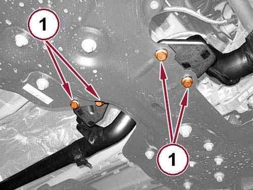
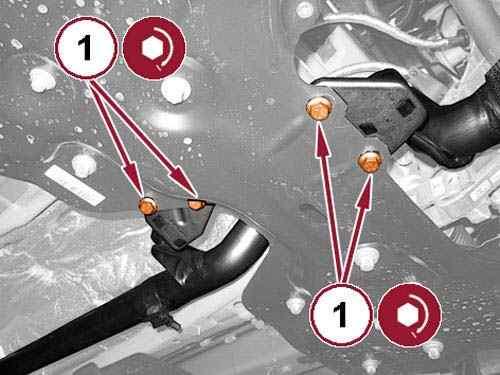
CLICK HERE TO DOWNLOAD THE COMPLETE MANUAL
• Thank you very much for reading the preview of the manual.
• You can download the complete manual from: www.heydownloads.com by clicking the link below

• Please note: If there is no response to CLICKING the link, please download this PDF first and then click on it.
CLICK HERE TO DOWNLOAD THE
TESTING .
5. Incorrect spark plug gap.5. Set the spark plug gap. Refer to SPECIFICATIONS .
6. Contamination in fuel system.6. Clean the fuel system and replace the fuel filter.
ENGINE STALLS OR IDLES ROUGH
7. Incorrect engine oil level and oil quality.
The engine starting should not be effected if the oil level shows anywhere on the dipstick. If the oil level is off the dipstick, the oil level could be contributing to the startability issue. If the oil quality is questionable, change the oil and filter.
8. Long Stand Still Parkinglonger than 35 days.
Perform a long start procedureCrank engine for 10 seconds, let sit for 5 seconds, crank for 10 seconds. May be necessary to continue sequence after a 30 second break.
9. Faulty fuel pump.7. Test the fuel pump and replace as needed. Refer to DIAGNOSIS AND TESTING .
8. Incorrect cam timing.8. Verify cam timing. Refer to STANDARD PROCEDURE .
10. Faulty Camshaft Position (CMP) sensor.
11. Faulty Crankshaft Position (CKP) sensor.
1. Idle speed too low.
Replace the Camshaft Position (CMP) sensor. Refer to SENSOR, CAMSHAFT POSITION, REMOVAL AND INSTALLATION .
Replace the Crankshaft Position (CKP) sensor. Refer to SENSOR, CRANKSHAFT POSITION, REMOVAL AND INSTALLATION .
1. Check for Diagnostic Trouble Codes (DTC). Refer to appropriate Engine Electrical Diagnostics article.
2. Incorrect fuel mixture.2. Check for Diagnostic Trouble Codes (DTC). Refer to appropriate Engine Electrical Diagnostics article.
3. Vacuum leak.
3. Inspect intake manifold, manifold gasket, and vacuum hoses.
4. Faulty ignition coil(s).4. Test and replace the ignition coil. Refer to COIL, IGNITION, REMOVAL AND INSTALLATION .
5. Faulty Crankshaft Position (CKP) sensor.
6. Incorrect cam timing.
ENGINE LOSS OF POWER1. Dirty or incorrectly gapped spark plugs.
5. Replace the Crankshaft Position (CKP) sensor. Refer to SENSOR, CRANKSHAFT POSITION, REMOVAL AND INSTALLATION .
6. Verify cam timing. Refer to STANDARD PROCEDURE .
1. Correct as necessary. Refer to SPARK PLUG, REMOVAL AND INSTALLATION .
2. Contamination in fuel system.2. Clean the fuel system and replace the fuel filter.
3. Faulty fuel pump.3. Test and replace the fuel pump. Refer to MODULE, FUEL PUMP, REMOVAL AND INSTALLATION .
4. Leaking cylinder head gasket.
5. Low compression.
6. Burned, warped, or pitted valves.
7. Plugged or restricted exhaust system.
4. Replace the cylinder head gasket. Refer to CYLINDER HEAD, REMOVAL AND INSTALLATION .
5. Determine the cause and repair as necessary. Refer to CYLINDER COMPRESSION TEST .
6. Replace valves as necessary. Refer to CYLINDER HEAD
7. Perform the exhaust restriction test. Install new parts as necessary. Refer to DIAGNOSIS AND TESTING .
8. Faulty ignition coil(s).8. Test and replace the ignition coil. Refer to COIL, IGNITION, REMOVAL AND INSTALLATION .
9. Incorrect valve timing.9. Verify cam timing. Refer to STANDARD PROCEDURE .
ENGINE MISSES ON ACCELERATION
1. Dirty or incorrectly gapped spark plugs.
ENGINE MISSES AT HIGH SPEED
1. Correct as necessary. Refer to SPARK PLUG, REMOVAL AND INSTALLATION .
2. Contamination in fuel system.2. Clean fuel system and replace the fuel filter.
3. Burned, warped, or pitted valves.
3. Replace valves as necessary. Refer to CYLINDER HEAD .
4. Faulty ignition coil(s).4. Test and replace the ignition coil. Refer to COIL, IGNITION, REMOVAL AND INSTALLATION .
1. Dirty or incorrect spark plug gap.
1. Correct as necessary. Refer to SPARK PLUG, REMOVAL AND
INSTALLATION .
2. Faulty ignition coil(s).2. Test and replace the ignition coil. Refer to COIL, IGNITION, REMOVAL AND INSTALLATION .
3. Contamination in fuel system.3. Clean the fuel system and replace the fuel filter.
4. Dirty fuel injector(s).4. Test and replace as necessary. Refer to DIAGNOSIS AND TESTING .
DIAGNOSIS AND TESTING > NOISY OPERATION
1.
You will hear a noise of high and constant intensity, coming from the engine area and detectable only within a certain range of RPM.
PRELIMINARY CHECKS
EVERYTHING OK PROBLEMS ENCOUNTERED RESOLUTION
Check the integrity and tightness of the circuit intake air Continue to Step 2 Circuit components damaged.
Repair or replace components as necessary.
2.
Check the engine mounts.
CHECK ENGINE MOUNTS
EVERYTHING OK PROBLEMS ENCOUNTERED RESOLUTION
1. Restore the correct fitting.
1. Fixing incorrect media engine
2. Support the engine gearbox side defective
3. Support engine timing side defective
Check the correct mounting and the integrity of:
- engine Supports - flexible blocks - guy reaction
Continue to Step 3
4. Support rear motor defective
5. Anchor elastic support front defective
6. Anchor elastic back support defective
7. Anchor elastic support gearbox side defective
8. Fixing incorrect tie rod reaction.
2. Replace the motor mount on the gearbox side.
3. Replace the motor mount side distribution.
4. Replace the rear motor mount.
5. Replace the elastic block front support.
6. Replace the elastic block back support.
7. Replace the elastic block support gearbox side.
8. Restore the correct fixing.
3.
Check the engine supports exhaust.
CHECK ENGINE SUPPORTS EXHAUST
EVERYTHING OK PROBLEMS ENCOUNTERED RESOLUTION
Check the correct support fixing sewage pipes.
Continue to Step 4
1. Supports loose.
2. Support damaged.
1. Restore the correct fixing of the supports.
2. Replace the damaged media.
4.
Check the engine exhaust.
CHECK ENGINE EXHAUST
Check the exhaust system of the engine and in particular:
- collector - conduit
- Exhaust silencer
- Seal front of the catalytic converter.
EVERYTHING OK PROBLEMS ENCOUNTERED RESOLUTION
End diagnosis
1. Full damaged pipe.
2. Silencer damaged.
3. Seal Front worn or damaged.
1. Replace the pipe complete
2. Replace the rear silencer
3. Replace the front seal
DIAGNOSIS AND TESTING > ENGINE MECHANICAL DIAGNOSTIC TABLE
CONDITION
NOISY VALVES
POSSIBLE CAUSES CORRECTIONS
1. High or low oil level in crankcase.
2. Thin or diluted oil.
3. Low oil pressure.
1. Adjust the engine oil level. Refer to FILTER, ENGINE OIL, REMOVAL AND INSTALLATION .
2. Change the engine oil and filter. Refer to FILTER, ENGINE OIL, REMOVAL AND INSTALLATION .
3. Check the oil pump, if OK, check the rod and main bearings for excessive wear. Refer to STANDARD PROCEDURE .
4. Dirt in valve lash adjusters.4. Replace as necessary. Refer to LIFTER(S), HYDRAULIC, REMOVAL AND INSTALLATION .
5. Worn rocker arms.5. Replace as necessary. Refer to CYLINDER HEAD .
6. Worn valve lash adjusters6. Replace as necessary. Refer to LIFTER(S), HYDRAULIC, REMOVAL
AND INSTALLATION .
7. Worn valve guides.7. Inspect the valve guides for wear, cracks or looseness. If either condition exists, replace the cylinder head. Refer to CYLINDER HEAD, REMOVAL AND INSTALLATION .
8. Excessive runout of valve seats or valve faces.
8. Replace as necessary. Refer to CYLINDER HEAD .
CONNECTING ROD NOISE1. Insufficient oil supply.1. Check and adjust the engine oil level. Refer to FILTER, ENGINE OIL, REMOVAL AND INSTALLATION .
2. Low oil pressure.2. Check the engine oil pump, if OK, check the rod and main bearings for excessive wear. Refer to STANDARD PROCEDURE .
3. Thin or diluted oil.3. Change the engine oil and filter. Refer to FILTER, ENGINE OIL, REMOVAL AND INSTALLATION .
4. Excessive bearing clearance.
5. Connecting rod journal out-of-round, rough surface or debris. Obstructed oil feed hole.
4. Replace as necessary. Refer to ENGINE BLOCK .
5. Service or replace the crankshaft. Check the crankshaft for plugged oil feed hole. Refer to ENGINE BLOCK .
6. Misaligned connecting rods.6. Replace the bent connecting rods. Refer to ROD, PISTON AND CONNECTING, REMOVAL AND INSTALLATION .
MAIN BEARING NOISE1. Insufficient oil supply.1. Check and adjust the engine oil level. Refer to FILTER, ENGINE OIL, REMOVAL AND INSTALLATION .
2. Low oil pressure.2. Check the engine oil pump, if OK, check the rod and main bearings for excessive wear. Refer to STANDARD PROCEDURE .
3. Thin or diluted oil.3. Change the engine oil and filter. Refer to FILTER, ENGINE OIL, REMOVAL AND INSTALLATION .
4. Excessive bearing clearance.
4. Replace as necessary. Refer to ENGINE BLOCK .
5. Excessive end play.5. Check the thrust washers for wear. Refer to ENGINE BLOCK .
6. Crankshaft journal out-of round, rough or debris. Obstructed oil feed hole.
7. Loose flywheel, flexplate or torque converter.
6. Service or replace the crankshaft. Check the engine block for plugged oil feed hole. Refer to ENGINE BLOCK .
7. Tighten to the proper specification. Refer to TORQUE SPECIFICATIONS .
DIAGNOSIS AND TESTING > CYLINDER COMPRESSION TEST
NOTE:
To perform a compression test on a MULTI-AIR equipped engine, the ignition MUST remain in the "key on" position. If the ignition is in the "off" position, the intake valves will not actuate and the result will be no compression.
NOTE:
The results of a cylinder compression pressure test can be utilized to diagnose several engine malfunctions.
NOTE:
Be certain the battery is completely charged and the engine starter motor is in good operating condition. Otherwise the indicated compression pressures may not be valid for diagnosis purposes.
Clean the spark plug recesses with compressed air.
1. Remove the spark plugs and record the cylinder number of each spark plug for future reference.
2. Inspect the spark plug electrodes for abnormal firing indicators such as fouled, hot, oily, etc.
3. Disable the fuel system and perform the fuel system pressure release procedure. Refer to FUEL DELIVERY, STANDARD PROCEDURE .
4. Insert a compression pressure gauge and rotate the engine with the engine starter motor for three revolutions.
6.
5. Record the compression pressure on the 3rd revolution. Continue the test for the remaining cylinders.
NOTE:
The recommended compression pressures are to be used only as a guide to diagnosing engine problems. An engine should not be disassembled to determine the cause of low compression unless some malfunction is present.
7.
Compression should not be less than 689 kPa (100 psi) and not vary more than 25 percent from cylinder to cylinder.
8.
If one or more cylinders have abnormally low compression pressures, repeat the compression test.
NOTE:
If the same cylinder or cylinders repeat an abnormally low reading on the second compression test, it could indicate the existence of a problem in the cylinder in question.
9.
If one or more cylinders continue to have abnormally low compression pressures, perform the cylinder combustion pressure leakage test. Refer to CYLINDER LEAKAGE TEST .
DIAGNOSIS AND TESTING > CYLINDER LEAKAGE TEST
The combustion pressure leakage test provides an accurate means for determining engine condition.
Cylinder leakage testing will detect:
Exhaust and intake valve leaks (improper seating).
Leaks between adjacent cylinders or into water jacket.
Any causes for combustion pressure loss.
1.
Check the coolant level and fill as required. DO NOT install the radiator cap.
2. Remove the spark plugs. 3.
Start and operate the engine until it attains normal operating temperature, then turn the engine OFF.
Remove the oil filler cap. 4. Remove the air cleaner hose. 5.
6.
Calibrate the tester according to the manufacturer's instructions. The shop air source for testing should maintain a regulated air pressure at 552 kPa (80 psi).
7.
Perform the test procedures on each cylinder according to the tester manufacturer's instructions. Set piston of cylinder to be tested at TDC compression.
CLICK HERE TO DOWNLOAD THE COMPLETE MANUAL
• Thank you very much for reading the preview of the manual.
• You can download the complete manual from: www.heydownloads.com by clicking the link below
• Please note: If there is no response to CLICKING the link, please download this PDF first and then click on it.
CLICK HERE TO DOWNLOAD THE
8.
While testing, listen for pressurized air escaping through the throttle body, tailpipe and oil filler cap opening. Check for bubbles in the radiator coolant.
All gauge pressure indications should be equal, with no more than 25% leakage.
If leakage is greater then 25%, refer to CYLINDER COMBUSTION PRESSURE LEAKAGE DIAGNOSIS CHART below.
CYLINDER COMBUSTION PRESSURE LEAKAGE DIAGNOSIS CHART
CONDITION POSSIBLE CAUSE CORRECTION
AIR ESCAPES THROUGH THROTTLE BODY
Intake valve bent, burnt, or not seated properly
AIR ESCAPES THROUGH TAILPIPE
Exhaust valve bent, burnt, or not seated properly
Inspect valve and valve seat. Reface or replace, as necessary. Inspect valve springs. Replace as necessary.
Inspect valve and valve seat. Reface or replace, as necessary. Inspect valve springs. Replace as necessary.
AIR ESCAPES THROUGH RADIATOR
MORE THAN 50% LEAKAGE FROM ADJACENT CYLINDERS
MORE THAN 25% LEAKAGE AND AIR ESCAPES THROUGH OIL FILLER CAP OPENING ONLY
Head gasket leaking or cracked cylinder head or block
Head gasket leaking or crack in cylinder head or block between adjacent cylinders
Stuck or broken piston rings; cracked piston; worn rings and/or cylinder wall
Remove cylinder head and inspect. Replace defective part
Remove cylinder head and inspect. Replace gasket, head, or block as necessary
Inspect for broken rings or piston. Measure ring gap and cylinder diameter, taper and out-of-round. Replace defective part as necessary
DIAGNOSIS AND TESTING > OIL CONSUMPTION TEST AND DIAGNOSIS
The following diagnostic procedures are used to determine the source of excessive internal oil Consumption, these procedures and tests apply to vehicles with 50, 000 miles or less.
NOTE:
Engine oil consumption may be greater than normal during engine break-in. Repairs should be delayed until vehicle has been driven at least 7, 500 miles.
Severe service (high ambient temperature, short trips, heavy loading, trailer towing, taxi, off-road, or law enforcement use) may result in greater oil consumption than normal.
Sustained high speed driving and high engine RPM operation may result in increased oil consumption.
Failure to comply with the recommended oil type and viscosity rating, as outlined in the owner's manual, may impact oil economy as well as fuel economy.
Oil consumption may increase with vehicle age and mileage due to normal engine wear.
NOTE:
Because a few drops of external oil leakage per mile can quickly account for the loss of one quart of oil in a few hundred miles, ensure no external engine oil leaks are present.
Oil leakage is not the same as oil consumption and all external leakage must be eliminated before any action can be taken to verify and/or correct oil consumption complaints.
Verify that the engine has the correct oil level dipstick and dipstick tube installed.
Verify that the engine is not being run in an overfilled condition. Check the oil level 15 minutes after a hot shutdown with the vehicle parked on a level surface. In no case should the level be above MAX or the FULL mark on the dipstick.
DIAGNOSIS AND TESTING > OIL CONSUMPTION TEST AND DIAGNOSIS > OIL CONSUMPTION TEST
1.
2.
Check the oil level at least 15 minutes after a hot shutdown with the vehicle on a level surface.
If the oil level is low, top off with the proper viscosity and API service level engine oil. Add one bottle of MOPAR® 4-In-1 Leak Detection Dye into the engine oil.
3.
Tamper proof the oil pan drain plug, oil filter, dipstick and oil fill cap with a black light marking device (pen) or air conditioning dye applied with a small brush.
NOTE:
The use of a black light marking device is recommended so the marks can only be seen with a ultraviolet light.
4.
Record the vehicle mileage. Note that the oil level at 'full' mark 15 minutes after hot shut-down and date.
Instruct the customer to drive the vehicle as usual. 5.
7.
Ask the customer to return to the servicing dealer after accumulating 500 miles, Check the oil level at least 15 minutes after a hot shutdown on a level surface. If the oil level is half way between the "FULL" and "ADD" mark or below, continue with the next step.
6. Using a black light, check for any external engine oil leaks, repair as necessary, if no external engine oil leaks are present, continue with oil consumption diagnosis.
DIAGNOSIS AND TESTING > OIL CONSUMPTION TEST AND DIAGNOSIS > OIL CONSUMPTION DIAGNOSIS
1.
Check the Positive Crankcase Ventilation (PCV) system. Make sure the system is not restricted, (one way by blowing air through it) and the PCV valve is the correct part based on the part number. Check the hoses and connectors for damage or leaks. It must have correct vacuum source at intake manifold through the hose- vent assembly. Normal vacuum is considered to be 18-20 in. Hg at idle, below 3000 ft. above sea level.
2.
Perform a cylinder compression test and cylinder leakage test using the standard cylinder leakage tester and following manufacturers suggested best practices. Refer to CYLINDER COMPRESSION TEST and CYLINDER LEAKAGE TEST .
NOTE:
Blow the spark plug sockets/bores out with compressed air to remove fluid or debris before removing the spark plugs.
Verify the spark plugs are not oil saturated.
3.
If one or more cylinders have more than 15% leak down further engine tear down and inspection will be required.
DIAGNOSIS AND TESTING > OIL CONSUM PTION TEST AND DIAGNOSIS > TOP 18 REASONS THAT MAY
LEAD TO ENGINE OIL CONSUMPTION
1. Distorted Cylinders
Tapered and Out-of-Round Cylinders
The increased piston clearances permit the pistons to rock in the worn cylinders. While tilted momentarily, an abnormally large volume of oil is permitted to enter on one side of the piston. The rings, also tilted in the cylinder, permit oil to enter on one side. Upon reversal of the piston on each stroke, some of this oil is passed into the combustion chamber.
2.
This may be caused by unequal heat distribution or unequal tightening of cylinder head bolts. This condition presents a surface which the rings may not be able to follow completely. In this case, there may be areas where the rings will not remove all of the excess oil. When combustion takes place, this oil will be burned and cause high oil consumption.
3.
Improper operation of "PCV" system
The main purpose of the Positive Crankcase Ventilation (PCV) valve is to recirculate blow-by gases back from the crankcase area through the engine to consume unburned hydrocarbons. The PCV system usually has a one way check valve and a make up air source. The system uses rubber hoses that route crankcase blow by gases to the intake manifold. Vacuum within the engine intake manifold pulls the blow by gases out of the crankcase into the combustion chamber along with the regular intake air and fuel mixture.
The PCV system can become clogged with sludge and varnish deposits and trap blow by gases in the crankcase. This degrades the oil, promoting additional formation of deposit material. If left uncorrected, the result is plugged oil rings, oil consumption, rapid ring wear due to sludge buildup, ruptured gaskets and seals due to crankcase pressurization.
If equipped with an engine driven vacuum pump, high oil consumption can be caused by unchecked airflow into the pump. This can be caused by anything that opens the vacuum pump intake port up to the atmosphere such as a faulty vacuum pump, hose fitting, hose and brake booster. If there is not a restriction (normally caused by the pump pulling vacuum on the brake booster), then the vacuum pump will pump a high volume of air. This high volume of air will pressurize the crankcase and cause excessive oil burning and oil flow through the PCV system.
4.
Worn Piston Ring Grooves
For piston rings to form a good seal, the sides of the ring grooves must be true and flat - not flared or shouldered. Piston rings in tapered or irregular grooves will not seal properly and, consequently, oil will pass around behind the rings into the combustion chamber.
5.
Worn, Broken or Stuck Piston Rings
When piston rings are broken, worn or stuck to such an extent that the correct tension and clearances are not maintained, this will allow oil to be drawn into the combustion chamber on the intake stroke and hot gases of combustion to be blown down the cylinder past the piston on the power stroke. All of these conditions will result in burning and carbon build up of the oil on the cylinders, pistons and rings.
6.
Cracked or Broken Ring Lands
Cracked or broken ring lands prevent the rings from seating completely on their sides and cause oil pumping. This condition will lead to serious damage to the cylinders as well as complete destruction of the pistons and rings. Cracked or broken ring lands cannot be corrected by any means other than piston replacement.
7.
Worn Valve Stems and Guides
When wear has taken place on valve stems and valve guides, the vacuum in the intake manifold will draw oil and oil vapor between the intake valve stems and guides into the intake manifold and then into the cylinder where it will be burned.
8.
Bent or Misaligned Connecting Rods
Bent or misaligned connecting rods will not allow the pistons to ride straight in the cylinders. This will prevent the pistons and rings from forming a proper seal with the cylinder walls and promote oil consumption. In addition, it is possible that a bearing in a bent connect rod will not have uniform clearance on the connecting rod wrist pin. Under these conditions, the bearing will wear rapidly and throw off an excessive amount of oil into the cylinder.
9.
Fuel Dilution
If raw fuel is allowed to enter the lubrication system, the oil will become thinner and more volatile and will result in higher oil consumption. The following conditions will lead to higher oil consumption:
Excess fuel can enter and mix with the oil via a leaking fuel injector 1.
Gasoline contaminated with diesel fuel 2.
Restricted air intake 3.
Excessive idling 4.
10.
Contaminated Cooling Systems
Corrosion, rust, scale, sediment or other formations in the water jacket and radiator will prevent a cooling system from extracting heat efficiently. This is likely to cause cylinder distortion thus leading to higher oil consumption.
11.
Oil Viscosity
The use of oil with a viscosity that is too light may result in high oil consumption. Refer to the vehicle owner's manual for the proper oil viscosity to be used under specific driving conditions and/or ambient temperatures.
12.
Dirty Engine Oil
Failure to change the oil and filter at proper intervals may cause the oil to be so dirty that it will promote accumulation of sludge and varnish and restrict oil passages in the piston rings and pistons. This will increase oil consumption; dirty oil by nature is also consumed at a higher rate than clean oil.
13.
Crankcase Overfull
Due to an error in inserting the oil dip stick so that it does not come to a seat on its shoulder, a low reading may be obtained. Additional oil may be added to make the reading appear normal with the stick in this incorrect position which will actually make the oil level too high. If the oil level is so high that the lower ends of the connecting rods touch the oil in the oil pan excessive quantities of oil will be thrown on the cylinder walls and some of it will work its way up into the combustion chamber.
14.
Excessively High Oil Pressure
A faulty oil pressure relief valve may cause the oil pressure to be too high. The result will be that the engine will be flooded with an abnormally large amount of oil in a manner similar to that which occurs with worn bearings. This condition may also cause the oil filter to burst.
15.
Aftermarket Performance Chips and Modification
Increasing performance through the use of performance/power enhancement products to a stock or factory engine will increase the chance of excessive oil consumption.
16.
Lugging Engine
Lugging is running the engine at a lower RPM in a condition where a higher RPM (more power/torque) should be implemented. Especially susceptible on vehicles equipped with a manual transmission. This driving habit causes more stress loading on the piston and can lead to increases in engine oil consumption.
17.
Turbocharged Engines
There is a possibility for PCV "push-over" due to higher crankcase pressure (as compared to naturally aspirated engines) which is normal for turbocharged engines. This condition causes varying amounts of engine oil to enter the intake manifold, charge air cooler and associated
plumbing to and from the charge air cooler, also a leaking turbocharger seal will draw oil into the combustion chamber where it will burn (blue smoke from tail pipe may be present) and form carbon deposits which contribute to further oil consumption as they interfere with proper engine function.
18.
Restricted Air Intake
Excessive restriction in the air intake system will increase engine vacuum and can increase oil consumption, an extremely dirty air filter would be one example of this situation.
DIAGNOSIS
AND TESTING > ENGINE LUBRICATION DIAGNOSTIC TABLE
CONDITION
OIL LEAKS
POSSIBLE CAUSES
1. Misaligned or damaged gaskets and O-rings.
2. Loose fasteners, broken or porous metal parts.
CORRECTION
1. Replace as necessary.
2. Repair or replace metal parts. Tighten fasteners to the proper specification. Refer to TORQUE SPECIFICATIONS .
3. Crankshaft rear oil seal.3. Replace the rear crankshaft oil seal. Refer to SEAL, CRANKSHAFT OIL, REAR, REMOVAL AND INSTALLATION .
4. Crankshaft rear oil seal surface scratched, nicked or grooved.
4. Polish or replace the crankshaft. Refer to ENGINE BLOCK .
5. Oil pan flange cracked.5. Replace the oil pan. Refer to PAN, OIL, REMOVAL AND INSTALLATION .
6. Damaged or misaligned crankshaft front oil seal.
7. Scratched or damaged vibration damper hub front oil seal surface.
OIL PRESSURE DROP1. Low oil level.
6. Replace the front crankshaft oil seal.
7. Polish or replace the vibration damper. Refer to DAMPER, VIBRATION, REMOVAL AND INSTALLATION .
1. Check and correct the engine oil level. Refer to LUBRICATION .
2. Faulty oil pressure sensor.2. Replace the oil pressure sensor.
3. Low oil pressure.
3. Check the main crankshaft bearing clearance. Refer to STANDARD PROCEDURE .
3. Check the rod bearing clearance. Refer to STANDARD PROCEDURE .
OIL PUMPING AT RINGS; SPARK PLUGS FOULING
4. Clogged oil filter.
5. Worn oil pump.
6. Thin or diluted oil.
7. Excessive bearing clearance.
4. Replace the engine oil filter. Refer to FILTER, ENGINE OIL, REMOVAL AND INSTALLATION .
5. Replace the engine oil pump. Refer to PUMP, ENGINE OIL, REMOVAL AND INSTALLATION .
6. Change the engine oil and filter. Refer to FILTER, ENGINE OIL .
7. Replace the crankshaft bearings. Refer to ENGINE BLOCK .
7. Replace the rod bearings. Refer to ENGINE BLOCK .
8. Oil pump relief valve stuck.8. Replace the engine oil pump. Refer to PUMP, ENGINE OIL, REMOVAL AND INSTALLATION .
1. Worn or damaged rings.1. Hone the cylinder bores and replace the piston rings. Refer to STANDARD PROCEDURE . Refer to RING(S), PISTON, REMOVAL AND INSTALLATION .
2. Carbon in oil ring slots.2. Replace the piston rings. Refer to RING(S), PISTON, REMOVAL AND INSTALLATION .
3. Worn valve guides.3. Replace the cylinder head. Refer to CYLINDER HEAD, REMOVAL AND INSTALLATION .
4. Leaking valve guide seals.4. Replace the valve guide seals. Refer to CYLINDER HEAD .
1. Obstructed or incorrect oil filter.
ENGINE OIL FILTER SWOLLEN OR BURST
2. Engine oil viscosity incorrect.
3. Excessive engine oil pressure.
STANDARD PROCEDURE > DUST COVERS AND CAPS
1. Install new oil filter and test engine oil pressure. Refer to DIAGNOSIS AND TESTING .
2. Change engine oil and test engine oil pressure. Refer to DIAGNOSIS AND TESTING .
3. Replace engine oil pump. Refer to PUMP, ENGINE OIL, REMOVAL AND INSTALLATION .
To avoid the possibility of dust, dirt, moisture and other foreign debris being introduced to the engine during service, cover or cap all openings when hoses and tubes are removed.
Covers installed over openings will reduce the possibility of foreign materials to entering the engine systems. Using miller tool Universal Protective Cap Set (special tool #10368, Set, Universal Protective Cap), select the appropriate cover needed for the procedure.
STANDARD PROCEDURE > ENGINE GASKET SURFACE PREPARATION
CLICK HERE TO DOWNLOAD THE COMPLETE MANUAL
• Thank you very much for reading the preview of the manual.
• You can download the complete manual from: www.heydownloads.com by clicking the link below
• Please note: If there is no response to CLICKING the link, please download this PDF first and then click on it.
CLICK HERE TO DOWNLOAD THE
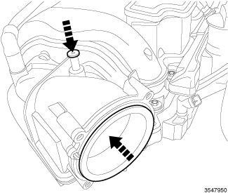
1 - ABRASIVE PAD
2 - 3M ROLOC™ BRISTLE DISC
3 - PLASTIC/WOOD SCRAPER
To ensure engine gasket sealing, proper surface preparation must be performed, especially with the use of aluminum engine components and multi-layer steel cylinder head gaskets.
Never use the following to clean gasket surfaces:
Metal scraper.
Abrasive pad or paper to clean cylinder block and head.
High speed power tool with an abrasive pad or a wire brush (1).
NOTE:
Multi-Layer Steel (MLS) head gaskets require a scratch free sealing surface.
Only use the following for cleaning gasket surfaces:
Solvent or a commercially available gasket remover
Plastic or wood scraper (3).
Drill motor with 3M Roloc™ Bristle Disc (white or yellow) (2).
CAUTION:
Excessive pressure or high RPM (beyond the recommended speed), can damage the sealing surfaces. The mild (white, 120 grit) bristle disc is recommended. If necessary, the medium (yellow, 80 grit) bristle disc may be used on cast iron surfaces with care.
STANDARD PROCEDURE > FORM-IN-PLACE GASKETS AND SEALERS
NOTE:
All of the sealants mentioned below are not used on every engine, they are listed as a general reference guide. See service information for specific sealer usage.
There are numerous places where form-in-place gaskets are used on the engine. Care must be taken when applying form-in-place gaskets to assure obtaining the desired results.Do not use form-in-place gasket material unless specified. Bead size, continuity, and location are of great importance. Too thin a bead can result in leakage while too much can result in spill-over which can break off and obstruct fluid feed lines. A continuous bead of the proper width is essential to obtain a leak-free gasket. All sealing surfaces that use form-in-place gaskets and sealers must be free of grease or oil. Surfaces should be cleaned with Mopar® brake parts cleaner prior to sealer application. After the sealer is applied, the parts should be assembled within 10 minutes.
There are numerous types of form-in-place gasket materials that are used in the engine area. Each has different properties and can not be used in place of the other.
SEALANT TYPES
MOPAR® ENGINE SEALANT RTV SILICONE RUBBER ADHESIVE is used to seal components exposed to engine oil. This material is a specially designed black silicone rubber RTV that retains adhesion and sealing properties when exposed to engine oil. Moisture in the air causes the material to cure. This material is available in three ounce tubes and has a shelf life of one year.
After one year this material will not properly cure. Always inspect the package for the expiration date before use.
MOPAR® ATF-RTV is a specifically designed black silicone rubber RTV that retains adhesion and sealing properties to seal components exposed to automatic transmission fluid, engine coolants, and moisture. This material is available in three ounce tubes and has a shelf life of one year. After one year this material will not properly cure. Always inspect the package for the expiration date before use.
MOPAR® GASKET MAKER is an anaerobic type gasket material. The material cures in the absence of air when squeezed between two metallic surfaces. It will not cure if left in the uncovered tube. The anaerobic material is for use between two machined surfaces. Do not use on flexible metal flanges.
MOPAR® BED PLATE SEALANT is a unique (green-in-color) anaerobic type gasket material that is specially made to seal the area between the bed plate and cylinder block without disturbing the bearing clearance or alignment of these components. The material cures slowly in the absence of air when torqued between two metallic surfaces, and will rapidly cure when heat is applied.
MOPAR® THREEBOND™ ENGINE RTV is formulated as a high performance temperature vulcanized silicone with good elasticity, temperature and chemical resistance when cured. It is resistant to engine oil, transmission fluid and gear lube but not recommended for sealing engine coolant.
SEALANT APPLICATION
Mopar® Gasket Maker material should be applied sparingly 1 mm (0.040 in.) diameter or less of sealant to one gasket surface. Be certain the material surrounds each mounting hole. Excess material can easily be wiped off. Components should be torqued in place within 15 minutes. The use of a locating dowel is recommended during assembly to prevent smearing material off the location.
Mopar® Engine Sealant RTV or ATF-RTV gasket material should be applied in a continuous bead approximately 3 mm (0.120 in.) in diameter. All mounting holes must be circled. For corner sealing and "T" joint locations, a 3.17 or 6.35 mm (1/8 or 1/4 in.) drop is placed in the center of the gasket contact area. Uncured sealant may be removed with a shop towel. Components should be torqued in place while the sealant is still wet to the touch (within 10 minutes). The usage of a locating dowel is recommended during assembly to prevent smearing material off the location.
Mopar® Threebond™ Engine RTV Sealant gasket material should be applied in a continuous bead approximately 3 mm (0.120 in.) in diameter. The gasket surfaces should be cleaned with isopropyl alcohol wipes in preparation for sealant application. All mounting holes must be circled. For corner sealing and "T" joint locations, a 3.17 or 6.35 mm (1/8 or 1/4 in.) drop is placed in the center of the gasket contact area. Uncured sealant may be removed with a shop towel. Components should be assembled within 20 minutes and torqued in place within 45 minutes. The usage of a locating dowel is recommended during assembly to prevent smearing material off the location.
STANDARD PROCEDURE > HYDROSTATIC LOCKED ENGINE
When an engine is suspected to be hydrostatically locked, regardless of what caused the problem, the following steps should be used.
CAUTION:
DO NOT use starter motor to rotate the engine, severe damage may occur.
1.
Inspect air cleaner, induction system and intake manifold to insure system is dry and clear of foreign material.
Disconnect and isolate the negative battery cable. If equipped with an Intelligent Battery Sensor (IBS), disconnect the IBS connector first before disconnecting the negative battery cable.
3.
2. Place a shop towel around the spark plugs when removing them from the engine. This will catch any fluid that may possibly be in the cylinder under pressure.
4. Identify the fluid in the cylinder(s) (i.e., coolant, fuel, oil or other).
With all spark plugs removed, rotate engine crankshaft using a breaker bar and socket.
5. Make sure all fluid has been removed from the cylinders. Inspect engine for damage (i.e., connecting rods, pistons, valves, etc.)
6. Repair engine or components as necessary to prevent this problem from re-occurring.
7. Install new spark plugs.
CAUTION:
Squirt approximately one teaspoon of oil into the cylinders, rotate engine to lubricate the cylinder walls to prevent damage on restart.
8. Drain engine oil and remove oil filter.
9. Install a new oil filter.
10. Fill engine with specified amount of approved oil.
11. Connect the negative battery cable. If equipped with an Intelligent Battery Sensor (IBS), connect the IBS connector to the negative battery cable.
13.
12. Start engine and check for any leaks.
STANDARD PROCEDURE > REPAIR DAMAGED OR WORN THREADS
CAUTION:
Be sure that the tapped holes maintain the original center line.
Damaged or worn threads can be repaired. Essentially, this repair consists of:
Drilling out worn or damaged threads.
Tapping the hole with a special Heli-Coil™ Tap, or equivalent.
Installing an insert into the tapped hole to bring the hole back to its original thread size.
SPECIFICATIONS > ENGINE SPECIFICATIONS
ENGINE TYPE -1.6 16V Multijet 120CV 1.6 16V Multijet 115CV 2.0 16V Multijet 120/140CV
16V Multijet 170CV
Position in vehicleFront Front Front Front OrientationTransverseTransverseTransverseTransverse
Camshaft configuration
ENGINE DATA
2 Cams in head (intake side and exhaust side)
2 Cams in head (intake side and exhaust side)
2 Cams in head (intake side and exhaust side)
2 Cams in head (intake side and exhaust side)
Maximum torque (RPM) 17501750125015001750
Idle speed (RPM)800 ± 30800 ± 30850 ± 30850 ± 30850 ± 30
Compression ratio16.5 : 116.5 : 116.5 : 116.5 : 116.5 : 1
TIMING ANGLES --1.6 16V Multijet2.0 16V Multijet
Operation control clearance (mm) Intake(•)(•) Exhaust(•)(•)
Control timing clearance (mm) Intake-Exhaust--
Intake Opening (BTDC)10°10°
(ATDC)--
(•) Hydraulic Tappets
CYLINDER BORE
Cylinder Bore Taper < 0.005
Turbo Diesel 2.0L Turbo Diesel
Oversize inner diameter cylinder bore (mm) 0.1 -
CYLINDER HEAD
Measure Value Engine
Cylinder head gasket thickness with maximum protrusion piston (mm)
Cylinder head gasket thickness with maximum protrusion piston (mm)
Cylinder head gasket thickness with maximum protrusion piston (mm)
Cylinder head gasket thickness with maximum protrusion piston (mm)
Cylinder head gasket thickness with maximum protrusion piston (mm)
Cylinder head gasket thickness with maximum protrusion piston (mm)
protrusion -0.020 ÷ + 0.100 thickness (no hole) 0.82 +/- 0.05 1.6L Turbo Diesel
protrusion+ 0.101 ÷ + 0.200 thickness (one hole) 0.92 +/- 0.05 1.6L Turbo Diesel
protrusion + 0.201 ÷ + 0.295 thickness (two holes) 1.02 +/0.05 1.6L Turbo Diesel
protrusion -0.110 ÷ + 0.230 thickness (no hole) 0.95 +/- 0.05 2.0L Turbo Diesel
protrusion -0.231 ÷ + 0.330 thickness (one hole) 0.95 +/- 0.05
Turbo Diesel
protrusion + 0.331 ÷ + 0.425 thickness (two holes) 1.15 +/0.05 2.0L Turbo Diesel
Nominal cylinder head height (mm) 107 +/- 0.05
Turbo Diesel
Flatness Cylinder Head Surface (mm) < 0.1 -
VALVES
Measure Value Engine
VALVE GUIDES
Measure Value Engine
Valve stem diameter- Intake (mm)
Valve stem diameter - Exhaust (mm)
VALVE SPRINGS
Valve
VALVE SEATS Measure Value Engine
Valve seat angle in contact with valve
CRANKSHAFT
Measure Value Engine
Connecting
Connecting
Connecting
MAIN BEARINGS/CRANKSHAFT CONNECTING ROD
Oversize
CLICK HERE TO DOWNLOAD THE COMPLETE MANUAL
• Thank you very much for reading the preview of the manual.
• You can download the complete manual from: www.heydownloads.com by clicking the link below
• Please note: If there is no response to CLICKING the link, please download this PDF first and then click on it.
CLICK HERE TO DOWNLOAD THE
Oversize bearing shells / connecting rod - Class B (Green) (mm)
Oversize bearing shells / connecting rod - Class C (Black) (mm)
Thickness of connecting rod bearing- Class A (Red) (mm)
Thickness of connecting rod bearing - Class B (Blue) (mm)
Thickness of connecting rod bearing - Class C (Yellow) (mm)
Thickness of connecting rod bearing- Class A (Red) (mm)
Thickness of connecting rod bearing - Class B (Blue) (mm)
Thickness of connecting rod bearing - Class C (Yellow) (mm) 1.535 ÷
Clearance of main bearingscrankshaft bearing journals (mm)
Clearance of main bearingscrankshaft bearing journals (mm)
Clearance of rod bearingscrankshaft rod bearings (mm)
PINS
Turbo Diesel
MeasureValueEngine
PISTON RINGS
Light scraper ring piston engine (mm)
Clearance of axial engine piston scraper ring (mm) 0.030 ÷ 0.070 1.6L Turbo Diesel 2.0L Turbo Diesel
Thickness 1^ seal ring compression cylinders (mm)
Thickness 2^ seal ring compression cylinders (mm) -1.6L Turbo Diesel
Thickness 3^ seal ring compression cylinders (mm)
Thickness 1^ seal ring compression cylinders (mm)
Thickness 2^ seal ring compression cylinders (mm) 1.470 ÷ 1.4952.0L Turbo Diesel
Thickness 3^ seal ring compression cylinders (mm) 1.970 ÷ 1.9902.0L Turbo Diesel
Seat seal on the piston - 1st slot (mm) 2.120 ÷ 2.1401.6L Turbo Diesel
Seat seal on the piston - 2nd slot (mm)
Seat seal on the piston - 3rd slot (mm) 2.020 ÷ 2.0401.6L Turbo Diesel
Seat seal on the piston - 1st slot (mm) 1.620 ÷ 1.6402.0L Turbo Diesel
Seat seal on the piston - 2nd slot (mm) 1.550 ÷ 1.5702.0L Turbo Diesel
Seat seal on the piston - 3rd slot (mm)
Axial 1^ seal ring compression cylinders (mm)
Axial 2^ seal ring compression cylinders (mm) 0.050 ÷ 0.0901.6L Turbo Diesel
Axial 1^ seal ring compression cylinders (mm) 0.125 ÷ 0.1702.0L Turbo Diesel
Axial 2^ seal ring compression cylinders (mm) 0.055 ÷ 0.1002.0L Turbo Diesel
PISTONS
Outside diameter pistons - Class A (mm)
Outside diameter pistons - Class B (mm)
Difference of weight allowed between pistons (g) +/-
Increase piston outer diameter (mm) 0.1
CONNECTING RODS
Inner
end of bushings
bushings
Diameter big end of bushings (mm)
CAMSHAFTS
Diameter Second pin timing shaft (mm)
Diameter Third pin timing shaft (mm)
Diameter Fourth pin timing shaft (mm)
Diameter
SPECIFICATIONS > TORQUE SPECIFICATIONS
ENGINE MOUNTS
Elastic Dowel of the powertrain support distribution side - rigid support side
Dowel of the powertrain support transmission siderigid support side
Elastic Dowel of the powertrain support transmission sidebodywork
Reaction of the lower bolt gearshift-side bracket
Reaction of the lower bolt gearshift-side suspension cross member
HEAD
CRANKSHAFT AND FLYWHEEL
PISTONS AND CONNECTING RODS
ENGINE TURBOCHARGER SYSTEM
INTAKE AND EXHAUST MANIFOLDS
CLICK HERE TO DOWNLOAD THE COMPLETE MANUAL
• Thank you very much for reading the preview of the manual.
• You can download the complete manual from: www.heydownloads.com by clicking the link below
• Please note: If there is no response to CLICKING the link, please download this PDF first and then click on it.
CLICK HERE TO DOWNLOAD THE
Engine oil pressure pipe to the Turboturbocharger side
Engine oil pressure pipe to the Turbocylinder head upper side
MISCELLANEOUS ENGINE PARTS
REMOVAL AND INSTALLATION > 1.6L DIESEL WITH MANUAL TRANSMISSION > REMOVAL
1.
Raise and support the vehicle. Refer to HOISTING, STANDARD PROCEDURE .
Remove the battery. Refer to BATTERY, REMOVAL AND INSTALLATION . 2.
3.
Remove the battery tray. Refer to TRAY, BATTERY, REMOVAL AND INSTALLATION .
Remove the front wheels. Refer to REMOVAL AND INSTALLATION . 4.
5.
Remove the front belly pan. Refer to BELLY PAN, REMOVAL AND INSTALLATION and BELLY PAN, SIDE, REMOVAL AND INSTALLATION .
6.
Remove the front wheel splash shields. Refer to SHIELD, SPLASH, FRONT WHEELHOUSE, REMOVAL AND INSTALLATION .
7. Remove the bolts (1) left side.
Remove the front fascia. Refer to FASCIA, FRONT, REMOVAL AND INSTALLATION . Fig 1: Left & Right Side Support Bolts
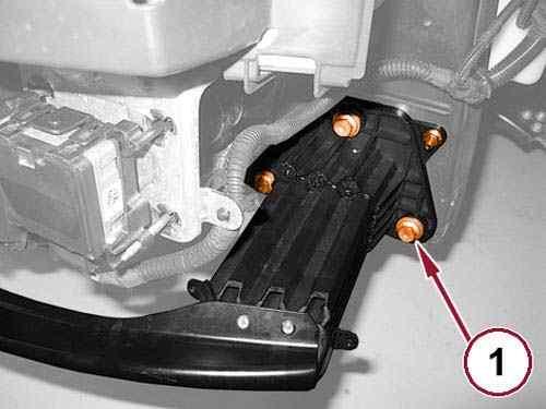
Courtesy of CHRYSLER GROUP, LLC
8. Remove the bolts right side.
9.
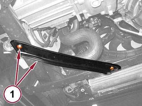
Remove the bolts (1) and the left side reinforcement. 10.
Remove the bolts and the right side reinforcement. 11.
12.
Remove the bolts (1) and the left side load beam.
Remove the engine cover. Refer to COVER, ENGINE, REMOVAL AND INSTALLATION . 13.
Remove the air cleaner body. 14.
Remove the fuel filter. Refer to FILTER, FUEL, REMOVAL AND INSTALLATION . 15.
Courtesy of CHRYSLER GROUP, LLC
16.
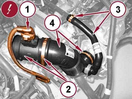
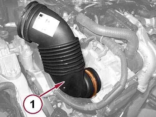
Disconnect the Mass Air Flow (MAF) sensor wire harness connector (1).
Loosen the clamp (2) and remove the MAF sensor from the turbocharger air inlet pipe (4). 17.
18.
Loosen the clamp (3) and disconnect the engine oil vapor hose from the tube side.
Loosen the clamp (4) and remove the air intake pipe from the turbocharger. 19.
Drain the transmission fluid. Refer to FLUID, STANDARD PROCEDURE . 20.
Drain the cooling system.
Refer to STANDARD PROCEDURE . 21.
Recover the refrigerant from the refrigerant system.
Refer to PLUMBING, STANDARD PROCEDURE .
22. Remove the left front head lamp. Refer to UNIT, FRONT LAMP, REMOVAL AND INSTALLATION . 23.
24.
Remove the right front head lamp. Refer to UNIT, FRONT LAMP, REMOVAL AND INSTALLATION .
25.
Remove the headlamp mounting crossmember. Refer to CROSSMEMBER, HEADLAMP
MOUNTING, REMOVAL AND INSTALLATION
26.
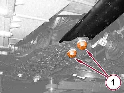
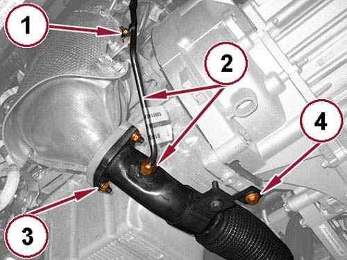
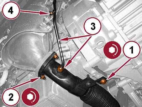
Remove the exhaust pipe hanger bolts (1).
27.
Remove the tube support bracket bolt (1).
28.
Loosen the tube nut (2) and reposition the tube.
29.
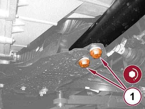
Remove the exhaust flange nuts (3).
30.
31.
Remove the exhaust pipe support bracket bolt (4).
Disconnect the exhaust pipe from the Diesel Particulate Filter (DPF) and remove the flange gasket.
32.
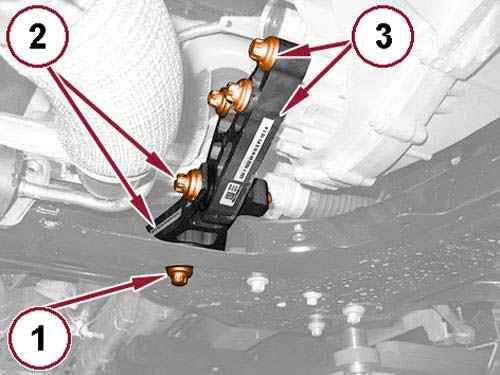
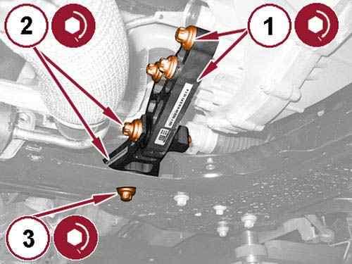
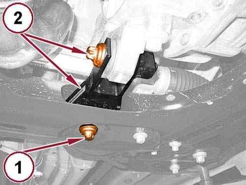
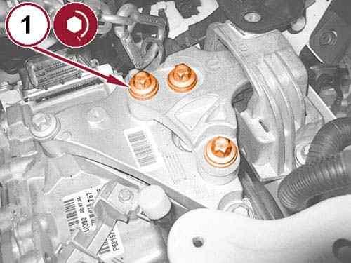
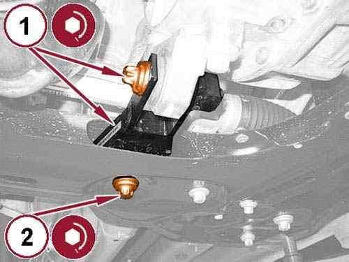
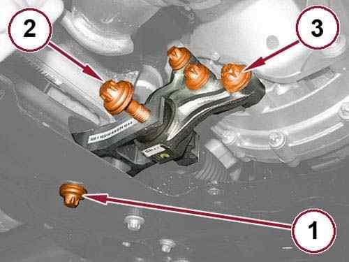
Remove the rear engine mount isolator to front crossmember bolt (1).
33.
Remove the bolt (2) and the rear engine mount isolator.
34.
Remove the bolts (3) and the rear engine mount isolator bracket.
35.
Remove the left and right half shafts. Refer to REMOVAL AND INSTALLATION .
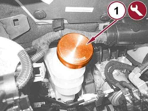
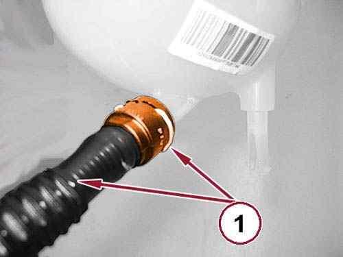
36.
Unscrew the cap for brake/clutch fluid reservoir and install the 2000001400 Cap Depression brake system/clutch (1).
CLICK HERE TO DOWNLOAD THE COMPLETE MANUAL
• Thank you very much for reading the preview of the manual.
• You can download the complete manual from: www.heydownloads.com by clicking the link below
• Please note: If there is no response to CLICKING the link, please download this PDF first and then click on it.
CLICK HERE TO DOWNLOAD THE
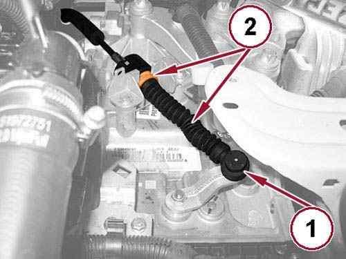
Disconnect the reverse lamp switch wire harness connector (1). 37.
Remove the bolt (2) and reposition the battery ground cable. 38.
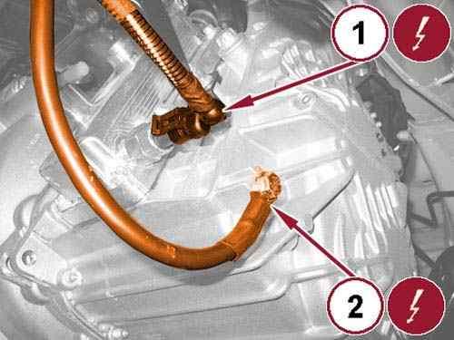
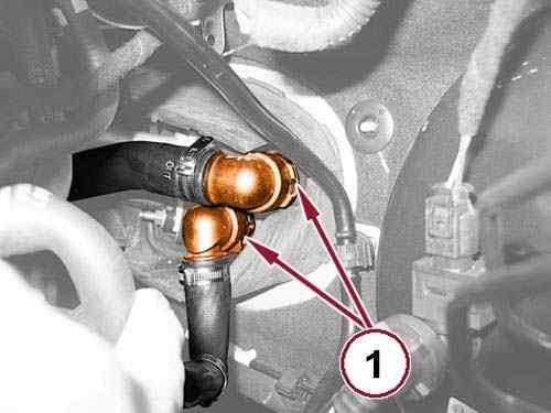
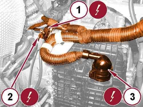
Disconnect the coolant hose quick couplings (1). 39.
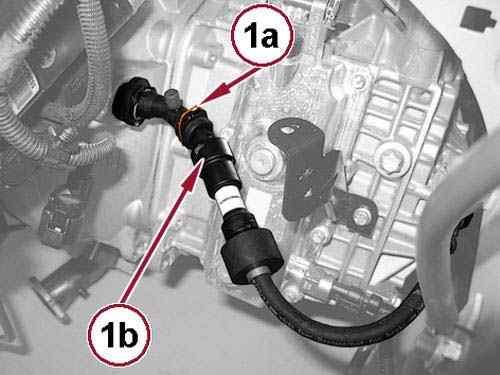
40.
Lift the retaining clip (1a) and disconnect the hose (1b) from the clutch slave cylinder.
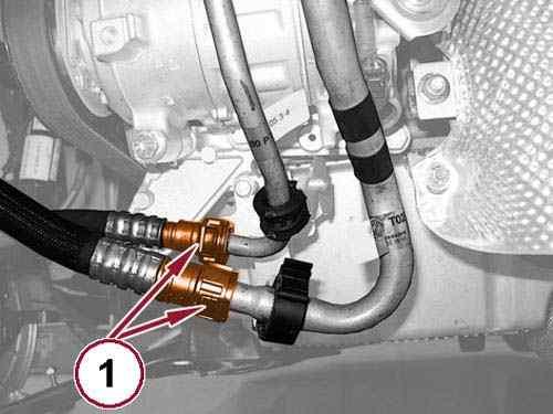
Disconnect the heater core hose quick couplings (1). 41.
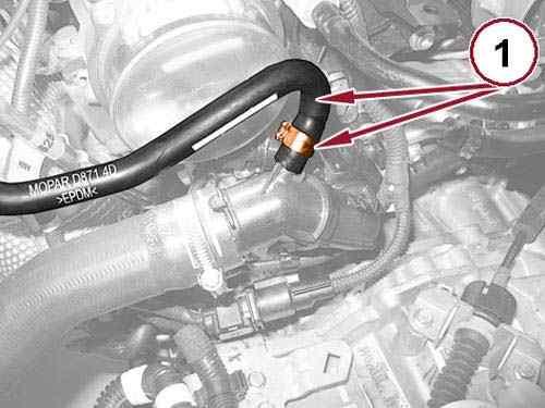
42.
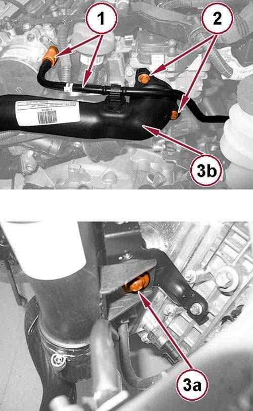
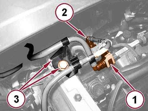
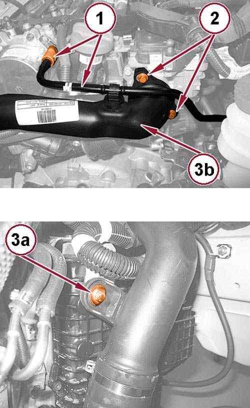
Disconnect the quick coupling (1) and remove the vacuum hose from the vacuum pump.
43.
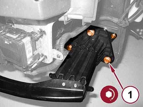
Remove the screws (2) securing the air delivery pipe to the throttle body.
44.
Remove the screw (3a) and remove the air delivery pipe from the throttle body (3b).
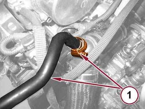
45.
Loosen the clamp (1) and remove the degas hose from the thermostat.
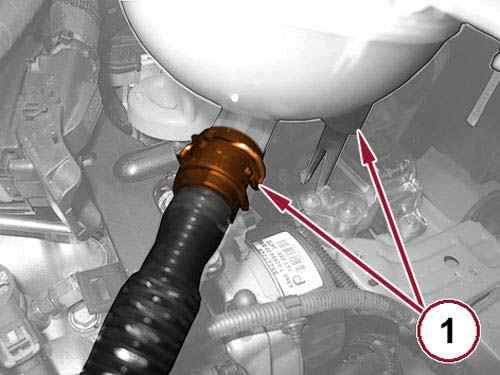
46.
Disconnect the quick coupling (1) and remove the pressurized coolant bottle.
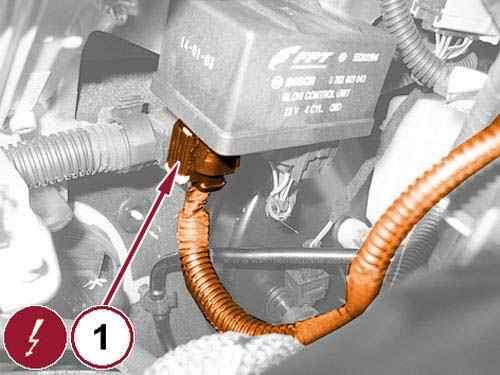
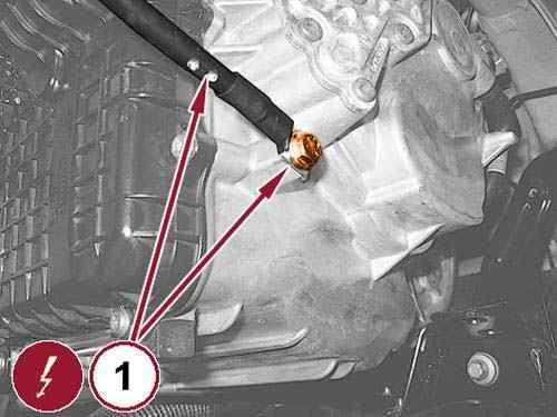
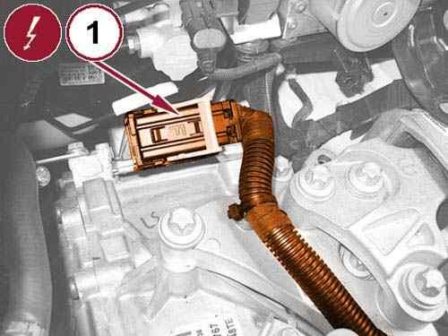
Disconnect the glow plug control unit wire harness connector (1). 47.
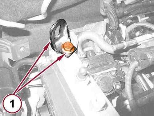
Disconnect the DPF differential pressure sensor wire harness connector (1). 48.
Unscrew the nut (2) and reposition the DPF differential pressure sensor onto the engine. 49.
CLICK HERE TO DOWNLOAD THE COMPLETE MANUAL
• Thank you very much for reading the preview of the manual.
• You can download the complete manual from: www.heydownloads.com by clicking the link below
• Please note: If there is no response to CLICKING the link, please download this PDF first and then click on it.
CLICK HERE TO DOWNLOAD THE
50.
Open the retaining clips and disengage the gear selector cables (1).
51.
Pull back the lock slider (2) and disengage the gear selector cable from the bracket.
52.
Pull back the lock slider (3) and disengage the gear selector cable from the bracket.
53.
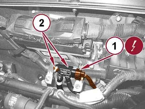
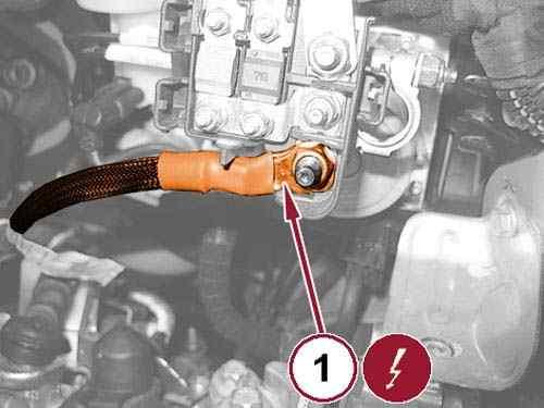
Remove the nut (1) and disconnect the starter cable from the positive battery terminal.
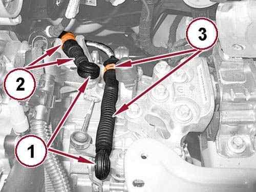
Fig 20: Retaining Clip, Powertrain Control Module (PCM) Wire Harness Connector & Engine Wire Harness Connector
54.
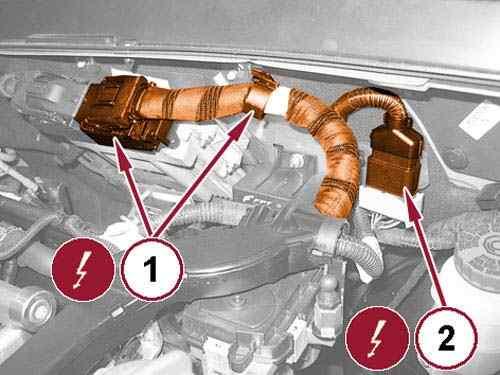
Open the retaining clip (1) and disconnect the Powertrain Control Module (PCM) wire harness connector.
55.
Disconnect the engine wire harness connector (2) and disengage the wiring from the spring retainer.
56.
Disconnect the fuel tank return line quick coupling (1).
57.
Disconnect the fuel supply line quick coupling (2).
58.
Remove the screw (3) and reposition the fuel lines retaining bracket.
59.
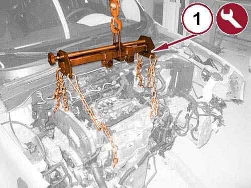
Connect a hydraulic crane and 1871001700 Sling (1) to the lifting brackets.
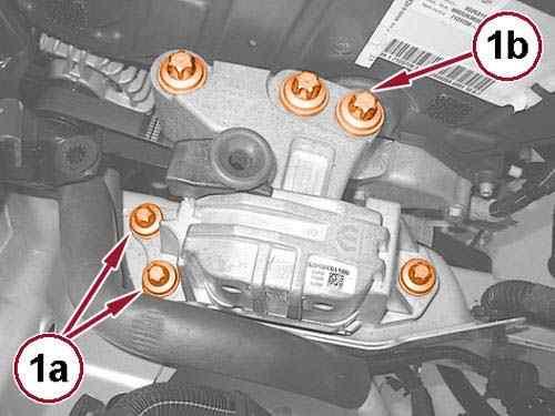
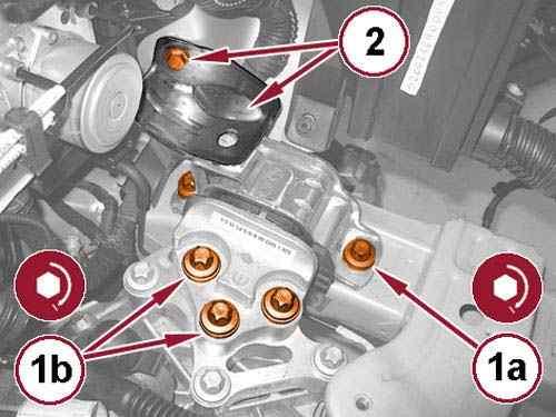
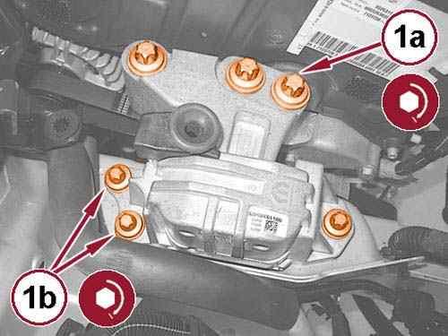
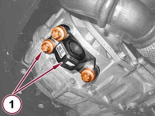
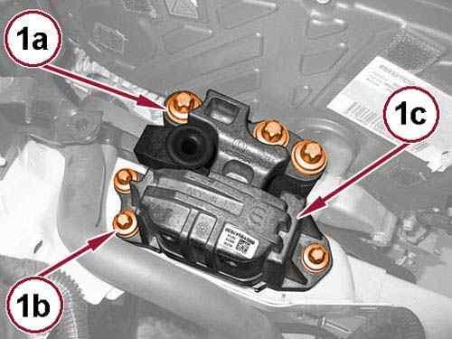
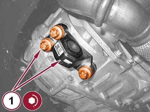
Remove the bolts (1a) and (1b) and remove the right engine mount isolator. 60.
61.
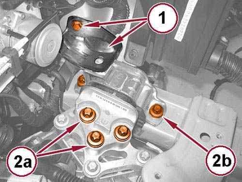
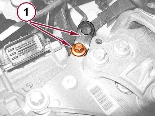
Remove the bolt (1) and the support bracket.
62.
Remove the bolts (2a) and (2b) and remove the left engine mount isolator.
63.
Remove the powertrain from the engine compartment and place it on a suitable platform.
64.
Remove the hydraulic crane and sling form the lifting brackets.
REMOVAL AND INSTALLATION > 1.6L DIESEL WITH MANUAL TRANSMISSION > INSTALLATION
1.
Install the powertrain in the engine compartment using a hydraulic crane and 1871001700 Sling connected to the lifting brackets.
2.
Install the left engine mount isolator and tighten the bolts (1a) and (1b) to the proper torque specification. Refer to TORQUE SPECIFICATIONS .
3.
Install the support bracket (2) with the bolt tightened to the proper torque specification. Refer to TORQUE SPECIFICATIONS .
4.
Install the right engine mount isolator and tighten the bolts (1a) and (1b) to the proper torque specification. Refer to TORQUE SPECIFICATIONS .
Remove the hydraulic crane and sling connected to the powertrain lifting brackets. 5.
6.
Install the fuel line retaining bracket with the screw tightened to the proper torque specification. Refer to TORQUE SPECIFICATIONS .
Connect the fuel supply line quick coupling. 7.
8.
Connect the fuel tank return line quick coupling.
Connect the engine wire harness connector and engage the wiring to the spring retainer. 9.
10.
Connect the Powertrain Control Module (PCM) wire harness connector and close the retaining clip.
11.
Install the starter cable to the positive battery terminal and tighten the nut to the proper torque specification. Refer to TORQUE SPECIFICATIONS .
Pull back the lock sliders and engage the gear selector cables to the brackets. 12.
13.
Open the retaining clips and engage the gear selector cables to the lever arms.
Install the DPF differential pressure sensor with the nut tightened to the proper torque 14.
CLICK HERE TO DOWNLOAD THE COMPLETE MANUAL
• Thank you very much for reading the preview of the manual.
• You can download the complete manual from: www.heydownloads.com by clicking the link below
• Please note: If there is no response to CLICKING the link, please download this PDF first and then click on it.
CLICK HERE TO DOWNLOAD THE
specification. Refer to TORQUE SPECIFICATIONS .
15.
Connect the DPF differential pressure sensor wire harness connector.
16.
Connect the glow plug control unit wire harness connector.
17.
18.
Install the pressurized coolant bottle and connect the quick coupling.
Install the degas hose to the thermostat and tighten the clamp to the proper torque specification. Refer to TORQUE SPECIFICATIONS .
19.
Install the air delivery pipe to the throttle body with the screws tightened to the proper torque specification. Refer to TORQUE SPECIFICATIONS .
20.
Secure the air delivery pipe to the support bracket with the screw tightened to the proper torque specification. Refer to TORQUE SPECIFICATIONS .
21.
Install the vacuum hose to the vacuum pump and connect the quick coupling.
22.
Connect the heater core hose quick couplings.
23.
Connect the hose to the clutch slave cylinder and engage the retaining clip.
24.
25.
Connect the coolant hose quick couplings.
Install the battery ground cable with the bolt tightened to the proper torque specification. Refer to TORQUE SPECIFICATIONS .
26.
Connect the reverse lamp switch wire harness connector.
27.
Install the left and right half shafts. Refer to REMOVAL AND INSTALLATION .
Courtesy of CHRYSLER GROUP, LLC
28.
Install the rear engine mount isolator bracket (1) with the bolts tightened to the proper torque specification. Refer to TORQUE SPECIFICATIONS .
29.
Install the rear engine mount isolator (2) with the bolt tightened to the proper torque specification. Refer to TORQUE SPECIFICATIONS .
30.
Install the rear engine mount isolator to front crossmember bolt (3) and tighten to the proper torque specification. Refer to TORQUE SPECIFICATIONS .
31.
32.
Install a new flange gasket and connect the exhaust pipe to the Diesel Particulate Filter (DPF).
Install the exhaust pipe support bracket bolt (1) and tighten to the proper torque specification. Refer to TORQUE SPECIFICATIONS .
33.
Install the exhaust flange nuts (2) and tighten to the proper torque specification. Refer to TORQUE SPECIFICATIONS .
34.
Connect the tube (3) and tighten the nut to the proper torque specification. Refer to TORQUE SPECIFICATIONS .
35.
Install the tube support bracket bolt (4) and tighten to the proper torque specification. Refer to TORQUE SPECIFICATIONS .
Courtesy of CHRYSLER GROUP, LLC
36.
Install the exhaust pipe hanger bolts (1) and tighten to the proper torque specification. Refer to TORQUE SPECIFICATIONS .
37.
Install the headlamp mounting crossmember. Refer to CROSSMEMBER, HEADLAMP MOUNTING, REMOVAL AND INSTALLATION .
38.
Install the right front head lamp. Refer to UNIT, FRONT LAMP, REMOVAL AND INSTALLATION .
39.
40.
Install the left front head lamp. Refer to UNIT, FRONT LAMP, REMOVAL AND INSTALLATION .
Install the air intake pipe to the turbocharger with the clamp tightened to the proper torque specification. Refer to TORQUE SPECIFICATIONS .
41.
Connect the engine oil vapor hose to the tube side with the clamp tightened to the proper torque specification. Refer to TORQUE SPECIFICATIONS .
42.
Install the MAF sensor to the turbocharger air inlet pipe with the clamp tightened to the proper torque specification. Refer to TORQUE SPECIFICATIONS .
43.
Connect the Mass Air Flow (MAF) sensor wire harness connector.
44.
Install the fuel filter. Refer to FILTER, FUEL, REMOVAL AND INSTALLATION .
45.
Install the air cleaner body.
Install the engine cover. Refer to COVER, ENGINE, REMOVAL AND INSTALLATION .
Fig 6: Left Side Load Beam Bolts
47.
Install the left side load beam (1) with the bolts tightened to the proper torque specification. Refer to TORQUE SPECIFICATIONS .
48.
Install the left side reinforcement with the bolts tightened to the proper torque specification. Refer to TORQUE SPECIFICATIONS .
49.
Install the bolts (1) left side and tighten to the proper torque specification. Refer to TORQUE SPECIFICATIONS .
50.
Install the bolts right side and tighten to the proper torque specification. Refer to TORQUE SPECIFICATIONS .
51.
Install the right side reinforcement with the bolts tightened to the proper torque specification. Refer to TORQUE SPECIFICATIONS .
52.
Install the battery tray. Refer to TRAY, BATTERY, REMOVAL AND INSTALLATION .
53.
Install the battery. Refer to BATTERY, REMOVAL AND INSTALLATION .
54.
Evacuate and charge the refrigerant system. Refer to PLUMBING, STANDARD PROCEDURE .
55.
Fill the cooling system. Refer to STANDARD PROCEDURE .
56.
Fill the transmission. Refer to FLUID, STANDARD PROCEDURE .
57.
Bleed the clutch hydraulic circuit. Refer to CLUTCH SYSTEM article.
58.
59.
Install the front fascia. Refer to FASCIA, FRONT, REMOVAL AND INSTALLATION .
Install the front wheel splash shields. Refer to SHIELD, SPLASH, FRONT WHEELHOUSE, REMOVAL AND INSTALLATION .
60.
Install the front belly pan. Refer to BELLY PAN, REMOVAL AND INSTALLATION and BELLY PAN, SIDE, REMOVAL AND INSTALLATION .
61.
Install the front wheels. Refer to REMOVAL AND INSTALLATION .
62.
Remove the vehicle from the lift.
REMOVAL AND INSTALLATION > 2.0L TURBO DIESEL WITH AUTOMATIC TRANSMISSION > REMOVAL
1.
Raise and support the vehicle. Refer to HOISTING, STANDARD PROCEDURE .
2.
Remove the hood. Refer to HOOD, REMOVAL AND INSTALLATION .
3.
Remove the battery. Refer to BATTERY, REMOVAL AND INSTALLATION .
4.
Remove the battery tray. Refer to TRAY, BATTERY, REMOVAL AND INSTALLATION .
5.
6.
Remove the front wheels. Refer to REMOVAL AND INSTALLATION .
Remove the front belly pan. Refer to BELLY PAN, REMOVAL AND INSTALLATION and BELLY PAN, SIDE, REMOVAL AND INSTALLATION .
7.
Remove the front wheel splash shields. Refer to SHIELD, SPLASH, FRONT WHEELHOUSE, REMOVAL AND INSTALLATION .
8.
Remove the front fascia. Refer to FASCIA, FRONT, REMOVAL AND INSTALLATION .
Remove the bolts (1) and the left lower load beam. 9.
Remove the bolts and the right lower load beam. 10.
Remove the engine cover. Refer to COVER, ENGINE, REMOVAL AND INSTALLATION . 11.
Remove the air cleaner body. 12.
Remove the fuel filter. Refer to FILTER, FUEL, REMOVAL AND INSTALLATION . 13.
Courtesy of CHRYSLER GROUP, LLC
14. Drain the cooling system.
Loosen the clamp and remove the air intake pipe from the turbocharger (1).
15. Recover the refrigerant from the refrigerant system.
Refer to STANDARD PROCEDURE .
Refer to PLUMBING, STANDARD PROCEDURE .
17.
16. Remove the left front head lamp. Refer to UNIT, FRONT LAMP, REMOVAL AND INSTALLATION
18.
Remove the right front head lamp. Refer to UNIT, FRONT LAMP, REMOVAL AND INSTALLATION .
19.
Remove the headlamp mounting crossmember. Refer to CROSSMEMBER, HEADLAMP MOUNTING, REMOVAL AND INSTALLATION .
CLICK HERE TO DOWNLOAD THE COMPLETE MANUAL
• Thank you very much for reading the preview of the manual.
• You can download the complete manual from: www.heydownloads.com by clicking the link below
• Please note: If there is no response to CLICKING the link, please download this PDF first and then click on it.
CLICK HERE TO DOWNLOAD THE
20.
Disconnect the quick coupling (1) and remove the coolant hose from the pressurized coolant bottle.
21.
Loosen the clamp (1), remove the degas hose from the thermostat and remove the pressurized coolant bottle from the vehicle.
Remove the exhaust pipe hanger bolts (1). 22.
Remove the exhaust flange nuts (1).
23. Remove the exhaust pipe support bracket bolt (2).
24.
25.
Disconnect the exhaust pipe from the Diesel Particulate Filter (DPF) and remove the flange gasket.
Position a suitable hydraulic lift under the powertrain (1). 26.
8: Rear Engine Mount Isolator To Front Crossmember Bolt & Rear Engine Mount Isolator Bolt
27.
Remove the rear engine mount isolator to front crossmember bolt (1).
28.
Remove the bolt (2) and the rear engine mount isolator.
29.
Remove the bolts and the rear engine mount isolator bracket (1).
Remove the left and right half shafts. Refer to REMOVAL AND INSTALLATION . 30.
Remove the bolt and reposition the battery ground cable (1). 31.
Disconnect the coolant hose quick couplings (1). 32.
CLICK HERE TO DOWNLOAD THE COMPLETE MANUAL
• Thank you very much for reading the preview of the manual.
• You can download the complete manual from: www.heydownloads.com by clicking the link below
• Please note: If there is no response to CLICKING the link, please download this PDF first and then click on it.
CLICK HERE TO DOWNLOAD THE
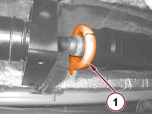
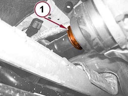
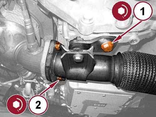
NOTE:
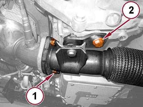
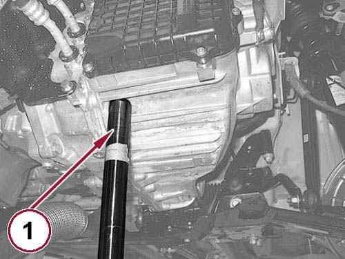
The protective sleeve is included in the service parts package which also includes new dust covers and snap rings.
Mount the protective sleeve (1) as shown in illustration to protect the joint from excessive bending. 33.
34.
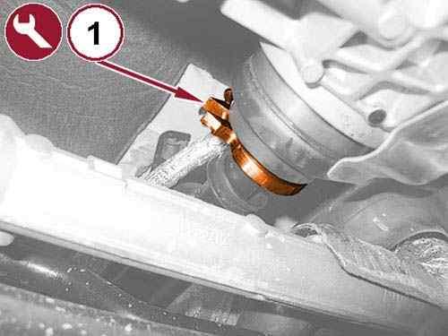
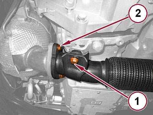
NOTE:
The dust cover must be replaced whenever the drive shaft is disconnected.
Pull back the dust cover (1).
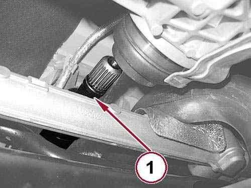
NOTE:
The snap ring must be replaced whenever the drive shaft is disconnected.
Using tool 2019500030 Retractor (1), open the snap ring. 35.
36.
Using the hydraulic lift, move the powertrain up and forward as much as permitted by the right and left engine mounts.
37.
Pull back the drive shaft to disengage it from the PTU and reposition the shaft on the crossmember.
38.
Remove the hydraulic lift.
of CHRYSLER GROUP, LLC
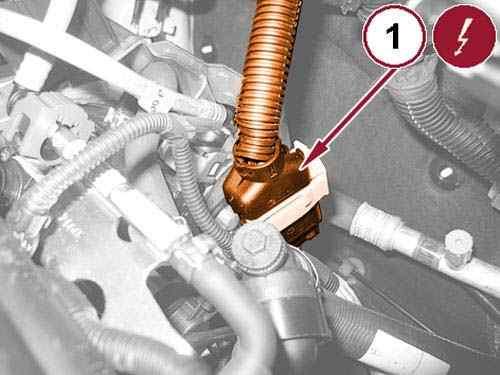
Disconnect the power transfer unit actuator wire harness connector (1). 39.
Disconnect the heater core hose quick couplings (1). 40.
41.
Disconnect the quick coupling (1) and remove the vacuum hose from the vacuum pump.
42.
Remove the screws (2) securing the air delivery pipe to the throttle body.
43.
Remove the screw (3a) and remove the air delivery pipe from the throttle body (3b).
Disconnect the glow plug control unit wire harness connector (1). 44.
Disconnect the DPF differential pressure sensor wire harness connector (1). 45.
Unscrew the nut (2) and reposition the DPF differential pressure sensor onto the engine. 46.
CLICK HERE TO DOWNLOAD THE COMPLETE MANUAL
• Thank you very much for reading the preview of the manual.
• You can download the complete manual from: www.heydownloads.com by clicking the link below
• Please note: If there is no response to CLICKING the link, please download this PDF first and then click on it.
CLICK HERE TO DOWNLOAD THE
47.
Disconnect the gear selector cable from the gear change lever (1).
Pull back the lock slider (2) and disengage the gear selector cable from the bracket. 48.
49.
Open the retaining clip and disconnect the Transmission Control Module (TCM) wire harness connector (1).
Fig 23: Downstream Oxygen Sensor, Exhaust Gas Temperature Sensor & Exhaust Gas Temperature Sensor Wire Harness Connectors
50.
Open the wire harness retaining clips.
Disconnect the downstream oxygen sensor wire harness connector (1). 51.
52.
Disconnect the exhaust gas temperature sensor wire harness connector (2).
Rotate the connector lock nut and disconnect the transmission wire harness connector (3). 53.
54.
Remove the nut (1) and disconnect the starter cable from the positive battery terminal.
Fig 25: Retaining Clip, Powertrain Control Module (PCM) Wire Harness Connector & Engine Wire Harness Connector
55.
Open the retaining clip (1) and disconnect the Powertrain Control Module (PCM) wire harness connector.
56.
Disconnect the engine wire harness connector (2) and disengage the wiring from the spring retainer.
57.
Disconnect the fuel tank return line quick coupling (1).
58.
Disconnect the fuel supply line quick coupling (2).
59.
Remove the screw (3) and reposition the fuel lines retaining bracket.
Install a suitable engine lifting bracket (1). 60.
61.
Install a suitable engine lifting bracket (1) under the left engine mount bracket bolt.
62.
Connect a hydraulic crane and 1871001700 Sling (1) to the lifting brackets.
CLICK HERE TO DOWNLOAD THE COMPLETE MANUAL
• Thank you very much for reading the preview of the manual.
• You can download the complete manual from: www.heydownloads.com by clicking the link below
• Please note: If there is no response to CLICKING the link, please download this PDF first and then click on it.
CLICK HERE TO DOWNLOAD THE
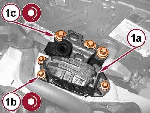
63.
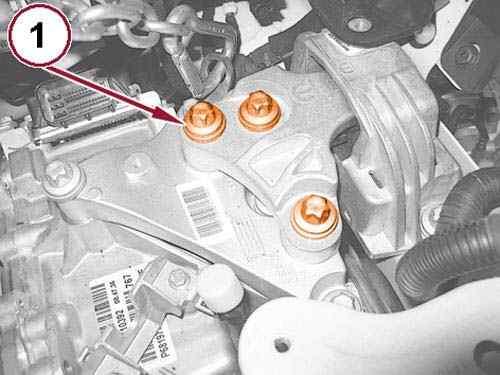
Remove the bolts (1a) and (1b) and remove the right engine mount isolator (1c).
64.
Remove the bolts (1) from the left engine mount isolator.
65.
Remove the powertrain from the engine compartment and place it on a suitable platform.
66.
Remove the hydraulic crane and sling form the lifting brackets.
REMOVAL AND INSTALLATION > 2.0L TURBO DIESEL WITH AUTOMATIC TRANSMISSION > INSTALLATION
1.
Install the powertrain in the engine compartment using a hydraulic crane and 1871001700 Sling connected to the lifting brackets.
Courtesy of CHRYSLER GROUP, LLC
2.
Install the left engine mount isolator bolts (1) and tighten to the proper torque specification. Refer to TORQUE SPECIFICATIONS .
3.
Install the right engine mount isolator (1a) and tighten the bolts (1b) and (1c) to the proper torque specification. Refer to TORQUE SPECIFICATIONS .
Remove the hydraulic crane and sling connected to the powertrain lifting brackets. 4.
5.
Install the fuel line retaining bracket with the screw tightened to the proper torque specification. Refer to TORQUE SPECIFICATIONS .
6.
Connect the fuel supply line quick coupling.
7.
Connect the fuel tank return line quick coupling.
8.
9.
Connect the engine wire harness connector and engage the wiring to the spring retainer.
Connect the Powertrain Control Module (PCM) wire harness connector and close the retaining clip.
10.
Install the starter cable to the positive battery terminal and tighten the nut to the proper torque specification. Refer to TORQUE SPECIFICATIONS .
Connect the transmission wire harness connector by rotating the connector lock nut. 11.
12.
Connect the exhaust gas temperature sensor wire harness connector.
13.
Connect the downstream oxygen sensor wire harness connector.
14.
15.
Close the wire harness retaining clips.
Connect the Transmission Control Module (TCM) wire harness connector and close the wire harness retaining clip.
16.
Pull back the lock slider and engage the gear selector cable to the bracket.
Engage the gear selector cable to the lever arm and check its function. 17.
18.
Install the DPF differential pressure sensor with the nut tightened to the proper torque specification. Refer to TORQUE SPECIFICATIONS .
19.
Connect the DPF differential pressure sensor wire harness connector.
20.
21.
Connect the glow plug control unit wire harness connector.
Install the air delivery pipe to the throttle body with a new gasket and tighten the screws to the proper torque specification. Refer to TORQUE SPECIFICATIONS .
22.
Install the vacuum hose quick coupling to the vacuum pump and engage the retaining clip.
23.
Connect the heater core hose quick couplings.
24.
Connect the power transfer unit actuator wire harness connector.
25.
Install a new drive shaft snap ring.
26.
Install a new drive shaft dust cover.
27.
Install the drive shaft into the power transfer unit and engage the snap ring.
28.
Install the drive shaft dust cover.
29.
Remove the drive shaft protective sleeve.
30.
31.
Connect the coolant hose quick couplings.
Install the battery ground cable with the bolt tightened to the proper torque specification. Refer to TORQUE SPECIFICATIONS .
32.
Install the left and right half shafts. Refer to REMOVAL AND INSTALLATION .
33.
Install the rear engine mount isolator bracket (1) with the bolts tightened to the proper torque specification. Refer to TORQUE SPECIFICATIONS .
34.
Install the rear engine mount isolator (1) with the bolt tightened to the proper torque specification. Refer to TORQUE SPECIFICATIONS .
35.
Install the rear engine mount isolator to front crossmember bolt (2) and tighten to the proper torque specification. Refer to TORQUE SPECIFICATIONS .
36.
Install a new flange gasket and connect the exhaust pipe to the Diesel Particulate Filter (DPF) with new nuts.
37.
Install the exhaust pipe support bracket bolt (1) and tighten to the proper torque specification. Refer to TORQUE SPECIFICATIONS .
38.
Tightened the new flange nuts (2) to the proper torque specification. Refer to TORQUE SPECIFICATIONS .
Courtesy of CHRYSLER GROUP, LLC
39.
Install the exhaust pipe hanger bolts (1) and tighten to the proper torque specification. Refer to TORQUE SPECIFICATIONS .
40.
41.
Install the pressurized coolant bottle and connect the quick coupling.
Install the degas hose to the thermostat and tighten the clamp to the proper torque specification. Refer to TORQUE SPECIFICATIONS .
42.
Install the headlamp mounting crossmember. Refer to CROSSMEMBER, HEADLAMP MOUNTING, REMOVAL AND INSTALLATION .
43.
Install the right front head lamp. Refer to UNIT, FRONT LAMP, REMOVAL AND INSTALLATION .
44.
45.
Install the left front head lamp. Refer to UNIT, FRONT LAMP, REMOVAL AND INSTALLATION .
Install the air intake pipe to the turbocharger with the clamp tightened to the proper torque specification. Refer to TORQUE SPECIFICATIONS .
46.
Install the fuel filter. Refer to FILTER, FUEL, REMOVAL AND INSTALLATION .
47.
Install the air cleaner body.
48.
Install the engine cover. Refer to COVER, ENGINE, REMOVAL AND INSTALLATION .
CLICK HERE TO DOWNLOAD THE COMPLETE MANUAL
• Thank you very much for reading the preview of the manual.
• You can download the complete manual from: www.heydownloads.com by clicking the link below
• Please note: If there is no response to CLICKING the link, please download this PDF first and then click on it.
CLICK HERE TO DOWNLOAD THE
Courtesy of CHRYSLER GROUP, LLC
49.
Install the left side lower load beam (1) with the bolts tightened to the proper torque specification. Refer to TORQUE SPECIFICATIONS .
50.
Install the right side lower load beam with the bolts tightened to the proper torque specification. Refer to TORQUE SPECIFICATIONS .
51.
52.
Install the front fascia. Refer to FASCIA, FRONT, REMOVAL AND INSTALLATION .
Install the front wheel splash shields. Refer to SHIELD, SPLASH, FRONT WHEELHOUSE, REMOVAL AND INSTALLATION .
53.
Install the front belly pan. Refer to BELLY PAN, REMOVAL AND INSTALLATION and BELLY PAN, SIDE, REMOVAL AND INSTALLATION .
54.
Install the front wheels. Refer to REMOVAL AND INSTALLATION .
55.
Install the battery tray. Refer to TRAY, BATTERY, REMOVAL AND INSTALLATION .
56.
Install the battery. Refer to BATTERY, REMOVAL AND INSTALLATION .
57.
Fill the cooling system. Refer to STANDARD PROCEDURE .
58.
Evacuate and charge the refrigerant system. Refer to PLUMBING, STANDARD PROCEDURE .
59.
Install the hood. Refer to HOOD, REMOVAL AND INSTALLATION .
60.
Remove the vehicle from the lift.
REMOVAL AND INSTALLATION > 2.0L DIESEL WITH MANUAL TRANSMISSION > REMOVAL
Raise and support the vehicle. Refer to HOISTING, STANDARD PROCEDURE . 1.
Remove the battery. Refer to BATTERY, REMOVAL AND INSTALLATION . 2.
Remove the battery tray. Refer to TRAY, BATTERY, REMOVAL AND INSTALLATION . 3.
Remove the front wheels. Refer to REMOVAL AND INSTALLATION . 4.
5.
Remove the front belly pan. Refer to BELLY PAN, REMOVAL AND INSTALLATION and BELLY PAN, SIDE, REMOVAL AND INSTALLATION .
6.
Remove the front wheel splash shields. Refer to SHIELD, SPLASH, FRONT WHEELHOUSE, REMOVAL AND INSTALLATION .
7. Remove the bolts (1) left side.
Remove the front fascia. Refer to FASCIA, FRONT, REMOVAL AND INSTALLATION . Fig 1: Left & Right Side Support Bolts
8. Remove the bolts right side.
9.
Remove the bolts (1) and the left side reinforcement. 10.
Remove the bolts and the right side reinforcement. 11.
12.
Remove the bolts (1) and the left side load beam.
Remove the engine cover. Refer to COVER, ENGINE, REMOVAL AND INSTALLATION . 13.
Remove the air cleaner body. 14.
Remove the fuel filter. Refer to FILTER, FUEL, REMOVAL AND INSTALLATION . 15.
Courtesy of CHRYSLER GROUP, LLC
16.
Disconnect the Mass Air Flow (MAF) sensor wire harness connector (1).
Loosen the clamp (2) and remove the MAF sensor from the turbocharger air inlet pipe (4). 17.
18.
Loosen the clamp (3) and disconnect the engine oil vapor hose from the tube side.
Loosen the clamp (4) and remove the air intake pipe from the turbocharger. 19.
Drain the transmission fluid. Refer to FLUID, STANDARD PROCEDURE . 20.
Drain the cooling system.
Refer to STANDARD PROCEDURE . 21.
Recover the refrigerant from the refrigerant system.
Refer to PLUMBING, STANDARD PROCEDURE .
22. Remove the left front head lamp. Refer to UNIT, FRONT LAMP, REMOVAL AND INSTALLATION . 23.
24.
Remove the right front head lamp. Refer to UNIT, FRONT LAMP, REMOVAL AND INSTALLATION .
25.
Remove the headlamp mounting crossmember. Refer to CROSSMEMBER, HEADLAMP
MOUNTING, REMOVAL AND INSTALLATION
26.
Remove the exhaust pipe hanger bolts (1).
27. Remove the exhaust flange nuts (2).
Remove the exhaust pipe support bracket bolt (1).
28.
29.
Disconnect the exhaust pipe from the Diesel Particulate Filter (DPF) and remove the flange gasket.
30.
Remove the rear engine mount isolator to front crossmember bolt (1).
31.
Remove the bolt (2) and the rear engine mount isolator.
32.
Remove the bolts (3) and the rear engine mount isolator bracket.
33.
Remove the left and right half shafts. Refer to REMOVAL AND INSTALLATION .
34.
Unscrew the cap for brake/clutch fluid reservoir and install the 2000001400 Cap Depression brake system/clutch (1).
CLICK HERE TO DOWNLOAD THE COMPLETE MANUAL
• Thank you very much for reading the preview of the manual.
• You can download the complete manual from: www.heydownloads.com by clicking the link below
• Please note: If there is no response to CLICKING the link, please download this PDF first and then click on it.
CLICK HERE TO DOWNLOAD THE
Disconnect the reverse lamp switch wire harness connector (1). 35.
36.
Remove the bolt (2) and reposition the battery ground cable.
Disconnect the coolant hose quick couplings (1). 37.
38.
Lift the retaining clip (1a) and disconnect the hose (1b) from the clutch slave cylinder.
Disconnect the heater core hose quick couplings (1). 39.
CLICK HERE TO DOWNLOAD THE COMPLETE MANUAL
• Thank you very much for reading the preview of the manual.
• You can download the complete manual from: www.heydownloads.com by clicking the link below
• Please note: If there is no response to CLICKING the link, please download this PDF first and then click on it.
CLICK HERE TO DOWNLOAD THE
40.
Disconnect the quick coupling (1) and remove the vacuum hose from the vacuum pump.
41.
Remove the screws (2) securing the air delivery pipe to the throttle body.
42.
Remove the screw (3a) and remove the air delivery pipe from the throttle body (3b).
43.
Loosen the clamp (1) and remove the degas hose from the thermostat.
44.
Disconnect the quick coupling (1) and remove the pressurized coolant bottle.
Disconnect the glow plug control unit wire harness connector (1). 45.
CLICK HERE TO DOWNLOAD THE COMPLETE MANUAL
• Thank you very much for reading the preview of the manual.
• You can download the complete manual from: www.heydownloads.com by clicking the link below
• Please note: If there is no response to CLICKING the link, please download this PDF first and then click on it.
CLICK HERE TO DOWNLOAD THE