SYMBOLS > DESCRIPTION > DESCRIPTION
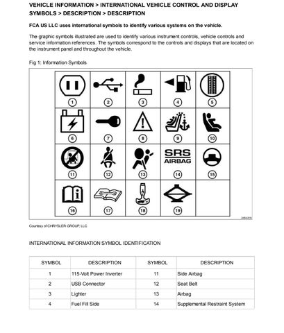
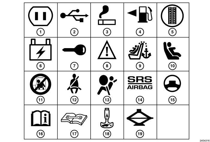
FCA US LLC uses international symbols to identify various systems on the vehicle.
The graphic symbols illustrated are used to identify various instrument controls, vehicle controls and service information references. The symbols correspond to the controls and displays that are located on the instrument panel and throughout the vehicle.
Courtesy of CHRYSLER GROUP, LLC
CLICK HERE TO DOWNLOAD THE COMPLETE MANUAL
• Thank you very much for reading the preview of the manual.
• You can download the complete manual from: www.heydownloads.com by clicking the link below

• Please note: If there is no response to CLICKING the link, please download this PDF first and then click on it.
CLICK HERE TO DOWNLOAD THE
5Spare Tire Winch 15Power Steering Fluid
6Fuse 16See Owner's Manual
7Key Activate (Power Outlet)17 See Appropriate Service Information
8Warning 18Emergency Release Handle
9Child Seat Tether Anchor 19Jack/Jack Tools Location
10 Lower Anchors and Tether for Children (Latch)
Courtesy of CHRYSLER GROUP, LLC
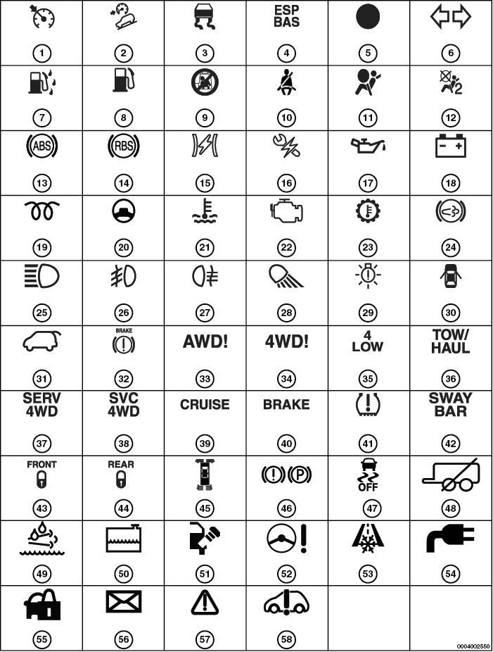
INTERNATIONAL INDICATOR SYMBOL IDENTIFICATION
SYMBOLDESCRIPTIONSYMBOLDESCRIPTION
1Electronic Speed Control30Door Ajar
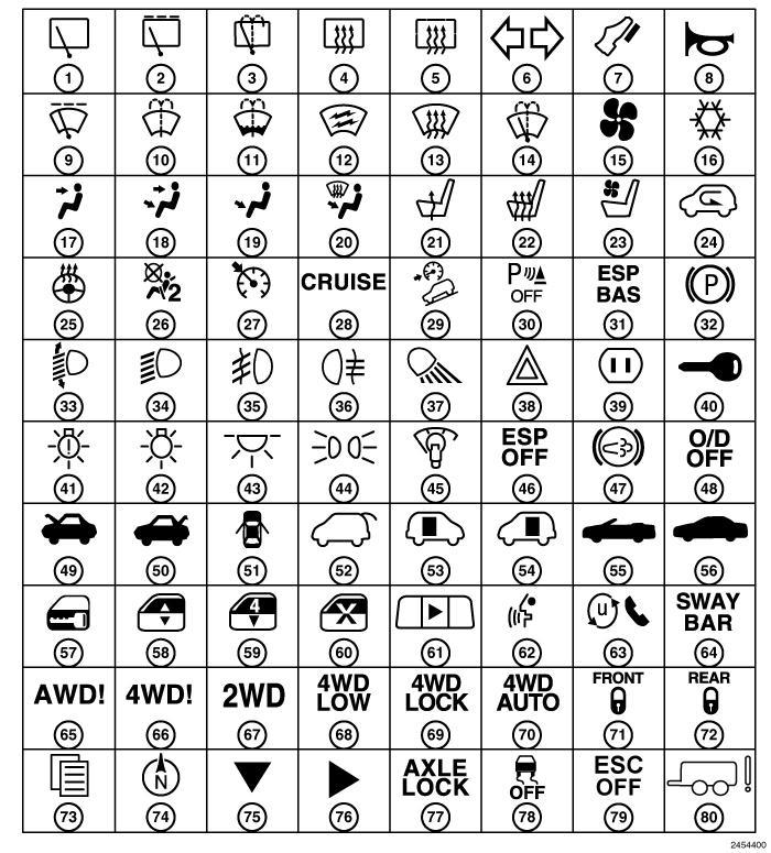
SYMBOLDESCRIPTIONSYMBOLDESCRIPTIONSYMBOLDESCRIPTION
23Ventilated Seat50Trunk/Deck Release77Axle Lock Button
24Recirculation51Door Ajar78Traction Control Off
25 Heated Steering Wheel 52Liftgate Release79 Electronic Stability Control Off
26 Passenger Air Bag Off 53Sliding Door 80Trailer Brakes
27 Electronic Speed Control 54Sliding Door
VEHICLE INFORMATION > INTERNATIONAL VEHICLE CONTROL AND DISPLAY SYMBOLS > DESCRIPTION > DESCRIPTION > ENGINE COMPARTMENT
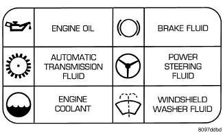
The graphic symbols illustrated are used to identify engine compartment lubricant and fluid inspection and fill locations. The symbols correspond to the caps located within the engine compartment.
VEHICLE INFORMATION > LABEL, VEHICLE EMISSION CERTIFICATION
INFORMATION (VECI) > DESCRIPTION > DESCRIPTION
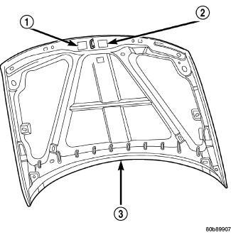
NOTE:
The Vehicle Emission Control Information (VECI) label(s) must be in place for the life of the vehicle. When replacing the component in which the VECI label is adhered, a new VECI
CLICK HERE TO DOWNLOAD THE COMPLETE MANUAL
• Thank you very much for reading the preview of the manual.
• You can download the complete manual from: www.heydownloads.com by clicking the link below
• Please note: If there is no response to CLICKING the link, please download this PDF first and then click on it.
CLICK HERE TO DOWNLOAD THE
label must also be adhered to the new component.
All vehicles are equipped with a combined VECI label(s). The label is located in the engine compartment on the vehicle hood. Two labels are used for vehicles built for sale in the country of Canada.
The VECI label(s) contain the following:
Engine family and displacement
Evaporative family
Certification application
Spark plug and gap
VEHICLE INFORMATION > VEHICLE CERTIFICATION LABEL > DESCRIPTION >
DESCRIPTION
1: Vehicle Certification Label - Typical
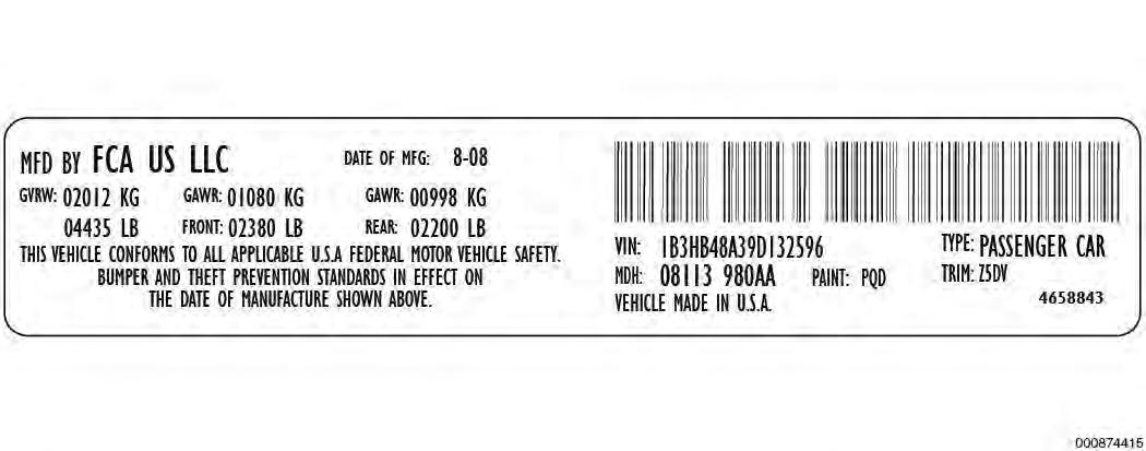
A vehicle certification label is attached to every FCA US LLC vehicle. The label certifies that the vehicle conforms to all applicable Federal Motor Vehicle Standards. The label also lists:
Month and year of vehicle manufacture.
Gross Vehicle Weight Rating (GVWR). The gross front and rear axle weight ratings (GAWR's) are based on a minimum rim size and maximum cold tire inflation pressure.
Vehicle Identification Number (VIN).
Type of vehicle.
Type of rear wheels.
Bar code.
Month, Day and Hour (MDH) of final assembly.
Paint and Trim codes.
Country of origin.
The label is located on the driver-side door shut-face.
VEHICLE INFORMATION > VEHICLE IDENTIFICATION NUMBER > DESCRIPTION > DESCRIPTION
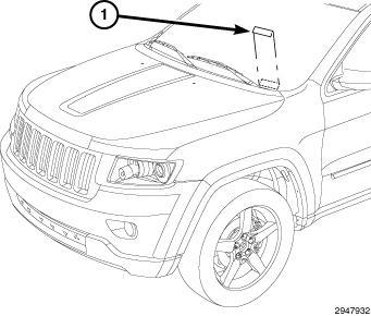
1: Vehicle Identification Number (VIN) Label
Courtesy of CHRYSLER GROUP, LLC
The Vehicle Identification Number (VIN) label (1) is attached to the top left side of the instrument panel. The VIN contains 17 characters that provide data concerning the vehicle. Refer to the decoding chart below to determine the identification of a vehicle.
To protect the consumer from theft and possible fraud the manufacturer is required to include a Check
Digit at the ninth position of the Vehicle Identification Number. The check digit is used by the manufacturer and government agencies to verify the authenticity of the vehicle and official documentation. The formula to use the check digit is not released to the general public.
VEHICLE INFORMATION > VEHICLE IDENTIFICATION NUMBER > DESCRIPTION >
DESCRIPTION > POSITIONS 1 - 3: WORLD MANUFACTURER IDENTIFIER
MANUFACTURER VEHICLE TYPE 1C4 Chrysler Group LLC (USA) MPV
VEHICLE INFORMATION > VEHICLE IDENTIFICATION NUMBER > DESCRIPTION >
DESCRIPTION > POSITION 4: BRAKE SYSTEM & GVWR
Brake System
PoundsKilograms
GVWR RangeActive Belts, Air Bags Active Belts, Air Bags, Side Bags-Front Row Active Belts, Air Bags, Side Bags-All Rows Active Belts, No Air Bags Active Belts, GVWR > 10, 000 lbs.
Hydraulic6001 - 7000 (2722 - 3175 KG) CJR--
VEHICLE INFORMATION > VEHICLE IDENTIFICATION NUMBER > DESCRIPTION > DESCRIPTION > POSITIONS 5 - 7:
Define the following: Brand, Marketing Name, Drive Wheels, Cab/Body Type, Drive Position, and Price Series.
VEHICLE INFORMATION > VEHICLE IDENTIFICATION NUMBER > DESCRIPTION >
DESCRIPTION > POSITION 8: ENGINE
CodeDisplacementCylindersFuelTurboSales Codes
M3.0 Liter6DieselYesEXF
83.0 Liter6GasolineNoEHD
G3.6 Liter6GasolineNoERB
T5.7 Liter8GasolineNoEZH
J6.4 Liter8GasolineNoESG
VEHICLE INFORMATION > VEHICLE IDENTIFICATION NUMBER > DESCRIPTION >
DESCRIPTION > POSITION 9: CHECK DIGIT
0 through 9 or X
VEHICLE INFORMATION > VEHICLE IDENTIFICATION NUMBER > DESCRIPTION >
DESCRIPTION > POSITION 10: MODEL YEAR
G = 2016
VEHICLE INFORMATION > VEHICLE IDENTIFICATION NUMBER > DESCRIPTION > DESCRIPTION > POSITION 11: ASSEMBLY PLANT Code Plant C Jefferson North Assembly
VEHICLE INFORMATION > VEHICLE IDENTIFICATION NUMBER > DESCRIPTION > DESCRIPTION > POSITION 12 - 17: PLANT SEQUENCE NUMBER
A six digit number assigned by assembly plant.
Cooling System
Engine Coolant (3.0L Diesel Engines)
Engine Coolant (3.0L/3.6L Gas Engines)
We recommend you use MOPAR® Antifreeze/Coolant 10 Year/150, 000 Mile Formula OAT (Organic Additive Technology).
We recommend you use MOPAR® Antifreeze/Coolant 10 Year/150, 000 Mile Formula OAT (Organic Additive Technology).
Engine Coolant (5.7L Engines without Trailer Tow Package)
Engine Coolant (5.7L Engines with Trailer Tow Package)
We recommend you use MOPAR® Antifreeze/Coolant 10 Year/150, 000 Mile Formula OAT (Organic Additive Technology).
We recommend you use MOPAR® Antifreeze/Coolant 10 Year/150, 000 Mile Formula OAT (Organic Additive Technology).
We recommend you use MOPAR® Antifreeze/Coolant 10
Engine Coolant (6.4L Engines)
Year/150, 000 Mile Formula OAT (Organic Additive Technology) hat meets the requirements of Material Standard MS.90032.
Engine Oil with Filter
Engine Oil (3.0L Diesel Engine)
Engine Oil (3.0L/3.6L Gas Engine- Domestic/Non-ACEA)
We recommend you use SAE 5W-30 Synthetic Low Ash Engine Oil meeting he requirements of Material Standard MS-11106 or 9.55535- S3 and approved ACEA C3 such as MOPAR or equivalent.
We recommend you use API Certified SAE 0W-20 Engine Oil, meeing the requirements of Material Standard MS-6395 such as MOPAR, Pennzoil, and Shell Helix. Refer to your engine oil filler cap for correct SAE grade.
8 Quarts 7.7 Liters
6 Quarts 5.6 Liters
Engine Oil (3.0L/3.6L Gas Engine- ACEA Categories)
Engine Oil (5.7L EngineDomestic/Non-ACEA)
We recommend you use API Certified SAE 0W-20 engine oil, meeting the requirements of Material Standard MS-6395 or 9.55535-CR1. Refer to your engine oil filler cap for the correct SAE grade.
We recommend you use API Certified SAE 5W-20 Engine Oil, meeing the requirements of Material Standard MS-6395 such as MOPAR, Pennzoil, and Shell Helix. Refer to your engine oil filler cap for correct SAE grade.
Engine Oil (5.7L Engine - ACEA Categories)
We recommend you use API Certified SAE 5W-20 engine oil, meeting the requirements of Material Standard MS-6395 or
6 Quarts 5.6 Liters
7 Quarts 6.6 Liters
7 Quarts 6.6 Liters
Engine Oil (6.4L Engine) Domestic and Export
9.55535-CR1. Refer to your engine oil filler cap for the correct SAE grade.
For best performance and maximum protection under all types of operating conditions, the manufacturer only recommends full synthetic engine oils that meet the American Petroleum Institute (API) categories of SN. The manufacturer recommends the use of Pennzoil Ultra 0W-40 or equivalent MOPAR engine oil meeting the requirements of Material Standard MS-12633 for use in all operating temperatures.
Engine Oil Filter (3.0L Diesel Engine)
Engine Oil Filter (3.0L/3.6L Gas Engine)
Engine Oil Filter (5.7L/6.4L Engine)
We recommend you use MOPAR Engine Oil Filter or equivalent.
We recommend you use MOPAR Engine Oil Filter or equivalent.
We recommend you use MOPAR Engine Oil Filter or equivalent.
Diesel Fuel Filter
Fuel (approximate)
We recommend you use MOPAR Fuel Filter. Must meet 3 micron rating. Using a fuel filter hat does not meet the manufacturers filtration and water separating requirements can severely impact fuel system life and reliability.
Fuel Selection (3.0L Diesel Engine)
Use good quality diesel fuel from a reputable supplier in your vehicle. Federal law requires that you must fuel this vehicle with Ultra Low Sulfur Highway Diesel fuel (15 ppm Sulfur maximum) and prohibits the use of Low Sulfur Highway Diesel fuel (500 ppm Sulfur maximum) to avoid damage to the emissions control system. For most year-round service, No. 2 diesel fuel meeting ASTM specification D-975 Grade S15 will provide good performance. We recommend you use a blend of up to 5% biodiesel, meeting ASTM specification D-975 with your diesel engine. This vehicle is compatible with biodiesel blends greater than 5% but no greater than 20% biodiesel meeting ASTM specification D-7467 provided the shortened maintenance intervals are followed as directed.
NOTE:
If the vehicle is exposed to extreme cold (below 20°F or -7°C), or is required to operate at colderthan-normal conditions for prolonged periods, use climatized No. 2 diesel fuel or dilute the No. 2 diesel fuel with 50% No. 1 diesel fuel. This will provide better protection from fuel gelling
24.6 Gallons 93.1 Liters
or wax-plugging of the fuel filters.
Fuel Selection (3.0L Diesel Engine - Europe)
Fuel Selection (3.0L/3.6L Gas Engine)
Fuel Selection (3.6L Gas EngineEurope)
50 Cetane or higher (Less than 10 ppm Sulfur)
24.6 Gallons93 Liters
87 Octane, 0-15% Ethanol.25 Gallons94 Liters
Minimum 91 Octane25 Gallons94 Liters
Fuel Selection (3.0L/ 3.6L Gas Engine) Flexible Fuel Ethanol E85 (ASTM D5798)25 Gallons94 Liters
Fuel Selection (5.7L Engine)
Fuel Selection (5.7L EngineEurope)
Fuel Selection (6.4L Engine)
Diesel Exhaust Fluid (DEF)
A/C Refrigerant System
89 Octane Recommended - 87 Octane Acceptable, 0-15% Ethanol.
Minimum 91 Octane Acceptable - 95 Octane Recommended
Premium Unleaded 91 Octane Only or Higher, 0-15% Ethanol.
MOPAR Diesel Exhaust Fluid (API Certified) (DEF) or equivalent that has been API Certified to the ISO 22241 standard. Use of fluids not API Certified to ISO 22241 may result in system damage.
25 Gallons94 Liters
25 Gallons94 Liters
25 Gallons94 Liters
8 Gallons30.3 Liters
A/C RefrigerantR-134a1.375 Pounds623.7 Grams
(1)
System fill capacity includes heater and coolant recovery bottle filled to MAX level.
(2) (3)
SAE 5W-30 engine oil approved to 9.55535 may be used when SAE 5W-20 engine oil is not available
MOPAR® SAE 5W-30 engine oil approved to MS-6395 such as Pennzoil® or Shell Helix® may be used when SAE 5W-20 engine oil meeting MS-6395 is not available.
Vehicles equipped with a 5.7L engine must use SAE 5W-20 oil. Failure to do so may result in improper operation of the Fuel Saver Technology.
CAUTION:
Nominal refill capacities are shown. A variation may be observed from vehicle to vehicle due to manufacturing tolerance and refill procedure.
SPARK PLUGS
DescriptionType
Spark Plugs (3.0L/3.6L Engine)
Spark Plugs (5.7L Engine)
Spark Plugs (6.4L Engine)
TRANSMISSION Description
We recommend you use MOPAR® Spark Plugs. 0043 in 1.10 mm
We recommend you use MOPAR® Spark Plugs. 0043 in 1.10 mm
We recommend you use MOPAR® Spark Plugs. 0043 in 1.10 mm
HP45 - 8 Speed
Use only Mopar® ZF 8&9 Speed ATF™ Automatic Transmission Fluid or equivalent. Failure to use the 8.98 Quarts 8.5 Liters
HP70 - 8 Speed
correct fluid may affect the function or performance of your transmission.
Use only Mopar® ZF 8&9 Speed ATF™ Automatic Transmission Fluid or equivalent. Failure to use the correct fluid may affect the function or performance of your transmission. 8.77 Quarts8.3 Liters
* Dry fill capacity. Depending on type and size of internal cooler, length and inside diameter of cooler lines, or use of an auxiliary cooler, these figures may vary. Refer to the appropriate service information for the correct procedures.
CAUTION:
Nominal refill capacities are shown. A variation may be observed from vehicle to vehicle due to manufacturing tolerance and refill procedure.
TRANSFER CASE DescriptionType
MP2010
MP3010
MP3023
CAUTION:
We recommend you use Automatic Transmission Fluid 3353.
Liters
MOPAR® ATF+4 Automatic Transmission Fluid 1.4 Quarts 1.35 Liters
MOPAR® ATF+4 Automatic Transmission Fluid 2.0 Quarts 1.9 Liters
Nominal refill capacities are shown. A variation may be observed from vehicle to vehicle due to manufacturing tolerance and refill procedure.
CHASSIS
Axles (Front)
195FIA FE - Front Axle
Axles (Rear)
195RIA - Rear Axle (Aluminum)
230RIA With Electronic Limited-Slip Differential (ELSD)-Rear Axle (Aluminum)
230RIA Without Electronic Limited-Slip Differential (ELSD) - Rear Axle (Aluminum)
Chassis Systems
Brake Master Cylinder
We recommend you use MOPAR GL-5 Synthetic Axle Lubricant SAE 75W-85. 0.9 Quarts 0.8 Liters
We recommend you use MOPAR GL-5 Synthetic Axle Lubricant SAE 75W-85. 1.0 Quarts 0.9 Liters
We recommend you use MOPAR GL-5 Synthetic Axle Lubricant SAE 75W-85 with friction modifier additive. 1.4 Quarts 1.3 Liters
We recommend you use MOPAR GL-5 Synthetic Axle Lubricant SAE 75W-85. 1.2 Quarts 1.1 Liters
We recommend you use MOPAR DOT 3 Brake Fluid, SAE J1703 should be used. If DOT 3, SAE J1703 brake fluid is not available, hen DOT 4 is
acceptable.
Power Steering Reservoir (Belt Driven Pump)
Power Steering Reservoir (Electric Pump)
(1) (1)
MOPAR® Power Steering Fluid +4
MOPAR® Hydraulic Fluid meeting the requirements of Material Standard MS-11655
N/A
N/A
N/A
N/A
If MOPAR® Power Steering Fluid +4 is not available, then MOPAR® ATF +4 Automatic Transmission Fluid, is acceptable.
CAUTION:
There is an Electro-Hydraulic Power Steering (EHPS) pump on some vehicles requiring a different fluid. Do not mix power steering fluid types. Damage may result to the power steering pump and system if any other fluid is used. The mechanical power steering pump systems on this vehicle require the use of Power Steering Fluid +4, which meets material specification MS-9602 or equivalent. The EHPS system uses fluid which meets material specification MS-11655 or equivalent. Do not overfill.
CAUTION:
Nominal refill capacities are shown. A variation may be observed from vehicle to vehicle due to manufacturing tolerance and refill procedure.
FUSE - RELAY LOCATIONS AND TYPES > SPECIFICATIONS > SPECIFICATIONS
NOTE:
Refer to the appropriate Wiring Application for Relay description and location information.
The Power Distribution Center is located in the engine compartment near he battery. This center contains cartridge fuses, micro fuses, relays, and circuit breakers. A description of each fuse and component may be stamped on the inside cover, otherwise the cavity number of each fuse is stamped on he inside cover that corresponds to the following chart.
POWER DISTRIBUTION CENTER
CavityCartridge FuseMicro FuseDescription
F0360 Amp Yellow-Radiator Fan
F0540 Amp Green-Compressor for Air Suspension - If Equipped
F0640 Amp Green-Anti-lock Brakes/Electronic Stability Control Pump
F0730 Amp Pink-Starter Solenoid
F0930 Amp Pink- Diesel Fuel Heater (Diesel engine only) / Brake Vacuum Pump
F1040 Amp Green-Body Controller / Exterior Lighting #2
F1130 Amp Pink-Trailer Tow Electric Brake - If Equipped
F1240 Amp Green-Body Controller #3 / Power Locks
F1340 Amp Green-Blower Motor Front
F1440 Amp Green-Body Controller #4 / Exterior Lighting #1
F1730 Amp Pink-Headlamp Washer- If Equipped
F1920 Amp Blue-Headrest Solenoid- If Equipped
F2030 Amp Pink-Passenger Door Module
F2220 Amp Blue-Engine Control Module
F2330 Amp Pink-Interior Lights #1
F2430 Amp Pink-Driver Door Module
F2530 Amp Pink-Front Wipers
CLICK HERE TO DOWNLOAD THE COMPLETE MANUAL
• Thank you very much for reading the preview of the manual.
• You can download the complete manual from: www.heydownloads.com by clicking the link below
• Please note: If there is no response to CLICKING the link, please download this PDF first and then click on it.
CLICK HERE TO DOWNLOAD THE
F26 30 Amp Pink -Anti-lock Brakes/Stability Control Module/Valves
F2820 Amp Blue-Trailer Tow Backup Lights - If Equipped
F2920 Amp Blue-Trailer Tow Parking Lights - If Equipped
F3030 Amp Pink-Trailer Tow Receptacle - If Equipped
F3230 Amp Pink-Drive Train Control Module
F3430 Amp Pink-Slip Differential Control
F3530 Amp Pink-Sunroof - If Equipped
F3630 Amp Pink-Rear Defroster
F3725 Amp Clear-Rear Blower Motor - If Equipped
F3830 Amp Pink-Power Inverter 115V AC - If Equipped
F3930 Amp Pink-Power Liftgate - If Equipped
F40-10 Amp RedDaytime Running Lights/Headlamp Leveling
F42-20 Amp YellowHorn
F44-10 Amp RedDiagnostic Port
F49-10 Amp RedIntegrated Central Stack / Climate Control
F50-20 Amp YellowAir Suspension Control Module - If Equipped
F51-15 Amp Blue Igniion Node Module / Keyless Ignition / Steering Column Lock
F52-5 Amp TanBattery Sensor
F53-20 Amp Yellow Trailer Tow - Left Turn/Stop Lights - If Equipped
F56-15 Amp BlueAdditional Content (Diesel engine only)
F57-20 Amp YellowNOX Sensor
F58-15 Amp BlueHID Headlamps LH - If Equipped
F59-10 Amp RedPurging Pump (Diesel engine only)
F60-15 Amp BlueTransmission Control Module
F61-10 Amp Red Transmission Control Module/PM Sensor (Diesel engine only)
F62-10 Amp RedAir Conditioning Clutch
F63-20 Amp YellowIgniion Coils (Gas), Urea Heater (Diesel)
F64-25 Amp ClearFuel Injectors / Powertrain
F66-10 Amp Red Sunroof / Passenger Window Switches / Rain Sensor
F67-15 Amp Blue CD / DVD / Bluetooth Hands-free Module - If Equipped
F68-20 Amp YellowRear Wiper Motor
F69-15 Amp BlueSpotlight Feed - If Equipped
F70-20 Amp YellowFuel Pump Motor
F71-30 Amp GreenAudio Amplifier
F72-10 Amp RedPCM (If Equipped)
F73-15 Amp BlueHID Headlamp RH - If Equipped
F75-10 Amp RedDual Batt Control (If Equipped)
F76-10 Amp RedAnti-lock Brakes/Electronic Stability Control
F77-10 Amp Red Drivetrain Control Module/Front Axle Disconnect Module
F78-10 Amp Red Engine Control Module / Electric Power Steering
F80-10 Amp Red Universal Garage Door Opener / Compass / Anti-Intrusion Module
F81-20 Amp YellowTrailer Tow Right Turn/Stop Lights
F82-10 Amp Red Steering Column Control Module/ Cruise Control / DTV
F83-10 Amp RedFuel Door
F84-15 Amp BlueSwitch Bank/Instrument Cluster
F85 - 10 Amp RedAirbag Module
F86 - 10 Amp RedAirbag Module
F87 - 10 Amp Red Air Suspension - If Equipped / Trailer Tow / Steering Column Control Module
F88 - 15 Amp BlueInstrument Panel Cluster
F90/F91 - 20 Amp YellowPower Outlet (Rear seats) Selectable
F92 - 10 Amp RedRear Console Lamp - If Equipped
F93 - 20 Amp YellowCigar Lighter
F94 - 10 Amp RedShifter / Transfer Case Module
F95 - 10 Amp RedRear Camera / ParkSense
F96 - 10 Amp Red Rear Seat Heater Switch / Flashlamp Charger - If Equipped
F97 - 20 Amp Yellow Rear Heated Seats & Heated Steering Wheel - If Equipped
F98 - 20 Amp YellowFront Heated Seats - If Equipped
F99 - 10 Amp Red Climate Control / Driver Assistance Systems Module / DSRC
F100 - 10 Amp RedActive Damping - If Equipped
F101 - 15 Amp Blue Electrochromatic Mirror/Smart High BeamsIf Equipped
F103 - 10 Amp Red Cabin Heater (Diesel Engine Only)/Rear HVAC
F104 - 20 Amp Yellow Power Outlets (Instrument Panel/Center Console)
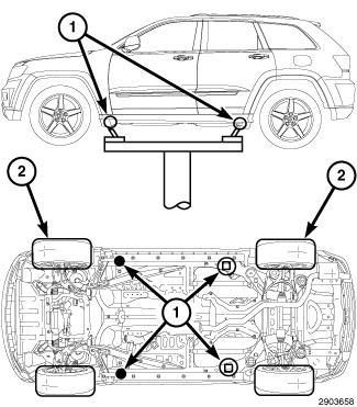
HOISTING > STANDARD PROCEDURE > STANDARD PROCEDURE - JACKING AND HOISTING LIFT POINTS
Courtesy of CHRYSLER GROUP, LLC
1 - FLOOR JACK, VEHICLE EMERGENCY JACK
1 - CHASSIS LIFT (DUAL POST)
1 - OUTBOARD LIFT (DUAL LIFT)
2 - DRIVE ON HOIST
Refer to Owner's Manual provided with vehicle for proper emergency jacking procedures.
WARNING:
The hoisting and jack lifting points provided are for a complete vehicle. When the engine or rear suspension is removed from a vehicle, the center of gravity is altered making some hoisting conditions unstable. Properly support or secure vehicle to hoisting device when these conditions exist. Failure to follow these instructions may result in personal injury or death.
WARNING:
Support the vehicle by supplemental means before performing any work on the air suspension system to prevent the vehicle from changing height. Before any given component is to be serviced it must be deflated. Servicing the air suspension system without supplemental su pport, or with pressure in the specific component, can cause possible serious or fatal injury.
NOTE:
The air suspension system will auto-disable when lifted on a frame hoist, or when jacking one corner of the vehicle. The air suspension may attempt to change height slightly prior to switching to auto-disable. A manual disable is also available by pressing the "Up" and "Down" switches of the terrain select switch simultaneously for more that 5 seconds. The air suspension system will return to normal operation when the vehicle speed reaches 25 kph (15 mph).
When properly positioned, a floor jack can be used to lift the vehicle and support the raised vehicle with jack stands.
A floor jack or any lifting device, must never be used on any part of the underbody other then the described areas.
CAUTION:
Do not attempt to lift a vehicle with a floor jack positioned under:
Aluminum differential.
A body side sill.
A steering linkage component.
A drive shaft.
The engine or transmission oil pan.
The fuel tank.
JUMP STARTING > STANDARD PROCEDURE > STANDARD PROCEDURE - JUMP STARTING
WARNING:
Review all safety precautions and warnings in the Battery System Service Information. Refer to BATTERY SYSTEM - SERVICE INFORMATION .
Do not jump start a frozen battery, personal injury can result.
If equipped, do not jump start when maintenance free battery indicator dot is yellow or bright color.
Do not jump start a vehicle when the battery fluid is below the top of lead plates.
Do not allow jumper cable clamps to touch each other when connected to a booster source.
Do not use open flame near battery.
Remove metallic jewelry worn on hands or wrists to avoid injury by accidental arcing of battery current.
When using a high output boosting device, do not allow battery voltage to exceed 16 volts. Refer to instructions provided with device being used.
Failure to follow these instructions may result in personal injury or death.
CAUTION:
When using another vehicle as a booster, do not allow vehicles to touch. Electrical systems can be damaged on either vehicle.
JUMP STARTING > STANDARD PROCEDURE > STANDARD PROCEDURE - JUMP STARTING > TO JUMP START A DISABLED VEHICLE:
Courtesy of CHRYSLER GROUP, LLC
On the disabled vehicle, remove the battery compartment lid from under the passenger seat and inspect the battery.
1.
Inspect the battery cable terminal clamps for damage. Replace any battery cable that has a damaged or deformed terminal clamp.
2.
3.
Inspect the battery tray and battery hold down hardware for damage. Replace any damaged parts.
Slide the thermal guard off of the battery case, if equipped. Inspect he battery case for cracks or other damage that could result in electrolyte leaks. Also, check the battery terminal posts for looseness. Batteries with damaged cases or loose terminal posts must be replaced.
4.
5.
Inspect the battery thermal guard for tears, cracks, deformation or oher damage. Replace any battery thermal guard that has been damaged.
Inspect the battery built-in test indicator sight glass (if equipped) for an indicaion of the battery condiion. If the battery is discharged, charge as required. Refer to BATTERY, AGM, STANDARD PROCEDURE .
2.
Raise hood on disabled vehicle and visually inspect engine compartment for: Generator drive belt condition and tension. 1.
CAUTION:
If the cause of starting problem on disabled vehicle is severe, damage to booster vehicle charging system can result.
3.
When using another vehicle as a booster source, park he booster vehicle within cable reach. Turn off all accessories, set the parking brake, place the automatic transmission in PARK or the manual transmission in NEUTRAL and turn the ignition OFF.
On disabled vehicle, place gear selector in park or neutral and set park brake. Turn off all accessories. 4.
5.
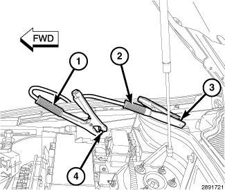
Connect jumper cables to booster battery. RED clamp to positive terminal (+). BLACK clamp to negative terminal (-). DO NOT allow clamps at opposite end of cables to touch, electrical arc will result. Review all warnings in this procedure.
6.
On the disabled vehicle, pull up and remove the protective cover over the remote positive (+) battery post (3).
Connect he RED jumper cable clamp (2) to positive (+) terminal (3). Connect BLACK jumper cable clamp (1) to engine ground (1). 7.
8.
Start the engine in the vehicle which has the booster battery, let the engine idle a few minutes, then start the engine in the vehicle with the discharged battery.
9.
CAUTION:
Do not crank starter motor on disabled vehicle for more than 15 seconds, starter will overheat and could fail.
Allow battery in disabled vehicle to charge to at least 12.4 volts (75% charge) before attempting to start engine. If engine does not start within 15 seconds, stop cranking engine and allow starter to cool (15 min.), before cranking again.
JUMP STARTING > STANDARD PROCEDURE > STANDARD PROCEDURE - JUMP STARTING > DISCONNECT CABLE CLAMPS AS FOLLOWS:
Disconnect BLACK cable clamp (1) from engine ground on disabled vehicle.
When using a Booster vehicle, disconnect BLACK cable clamp from battery negative terminal. Disconnect RED cable clamp from battery positive terminal.
Disconnect RED cable clamp (2) from battery positive terminal on disabled vehicle.
MAINTENANCE SCHEDULES > DESCRIPTION > MAINTENANCE SCHEDULES - NAFTA
Your vehicle is equipped with an automatic oil change indicator system. The oil change indicator system will remind you hat it is time to take your vehicle in for scheduled maintenance. Based on engine operation conditions, the oil change indicator message will illuminate. This means that service is required for your vehicle. Operating conditions such as frequent short trips, trailer tow, extremely hot or cold ambient temperatures, and E85 fuel usage will influence when the "Oil Change Required" message is displayed. Severe Operating Conditions can cause the change oil message to illuminate as early as 3, 500 miles (5, 600 km) since last reset. Have your vehicle serviced as soon as possible, within he next 500 miles (805 km).
NOTE:
Under no circumstances should oil change intervals exceed 10, 000 miles (16, 000 km), twelve months or 350 hours of engine run time, whichever comes first. The 350 hours of engine run or idle time is generally only a concern for fleet customers.
Oil
Change Indicator - RESET
Unless reset, this message continues to display each time you turn the igniion switch to the ON/RUN position. To turn off the message temporarily, press and release the Menu button. To reset the oil change indicator system (after performing the scheduled maintenance) perform the following procedure:
Turn the ignition switch to the "ON" position (Do not start the engine).
Fully depress the accelerator pedal slowly three times within 10 seconds.
Turn the ignition switch to the "LOCK" position.
NOTE:
If the indicator message illuminates when you start the vehicle, the oil change indicator system did not reset. If necessary repeat this procedure.
Severe Duty All Models
Change Engine Oil at 4, 000 miles (6, 500 km) if the vehicle is operated in a dusty and off road environment or is operated predominately at idle or only very low engine RPM's. This type of vehicle use is considered Severe Duty.
Once a Month Or Before a Long Trip
Check engine oil level
Check windshield washer fluid level
Check tire inflation pressures and look for unusual wear or damage.
Check the fluid levels of the coolant reservoir, brake master cylinder and fill as needed.
Check function of all interior and exterior lights.
At Every Oil Change Interval As Indicated By Oil Change Indicator System:
Change the engine oil filter.
Rotate the tires. Rotate at the first sign of irregular wear, even if it occurs before the oil indicator system turns on.
Inspect battery and clean and tighten terminals as required.
Inspect brake pads, shoes, rotors, drums, hoses and park brake.
Inspect engine cooling system protecion and hoses.
Inspect exhaust system.
Inspect engine air cleaner if using in dusty or off-road conditions.
MAINTENANCE CHART
or time
(whichever comes first)
Or Years:23456789101112131415
Kilometers:32,
Additional Inspections
Inspect the CV joints.
Inspect front suspension, tie rod ends, and replace if necessary.
Inspect the front and rear axle fluid, change if using your vehicle for police, taxi, fleet, off-road or frequent trailer towing.
Inspect the brake linings, parking brake function.
Inspect transfer case fluid.
Additional Maintenance
Replace engine air filter.
Replace the air conditioning filter.
Replace spark plugs.**
Flush and replace the engine coolant at 10 years or 150, 000 miles (240, 000 km) whichever comes first.
Change transfer case fluid.
Inspect and replace PCV valve if necessary.
** The spark plug change interval is mileage based only, yearly intervals do not apply.
MAINTENANCE
The Scheduled Maintenance services listed in this Service Information must be done at the times or mileages specified to protect your vehicle warranty and ensure the best vehicle performance and reliability. More frequent
maintenance may be needed for vehicles in severe operating conditions, such as dusty areas and very short trip driving. Inspection and service should also be done anytime a malfunction is suspected. The oil change indicator system will remind you that it is time to take your vehicle in for scheduled maintenance. The Driver Information Display (DID) will display an "Oil Change Required" message and a single chime will sound, indicating hat an oil change is necessary. Based on engine operation conditions, the oil change indicator message will illuminate. This means hat service is required for your vehicle. Have your vehicle serviced as soon as possible, within the next 500 miles (805 km).
NOTE:
The oil change indicator message will not monitor the time since the last oil change. Change your vehicle's oil if it has been six months since your last oil change, even if the oil change indicator message is NOT illuminated.
NOTE:
Change your engine oil more often if you drive your vehicle off-road for an extended period of time.
NOTE:
Under no circumstances should oil change intervals exceed 6, 000 miles (10, 000 km) or six months, whichever comes first.
Oil Change Indicator - RESET
Unless reset, this message continues to display each time you turn the igniion switch to the ON/RUN position. To turn off the message temporarily, press and release the Menu button. To reset the oil change indicator system (after performing the scheduled maintenance) perform the following procedure:
Turn the ignition switch to the "ON" position (Do not start the engine).
Fully depress the accelerator pedal slowly three times within 10 seconds.
Turn the ignition switch to the "LOCK" position.
NOTE:
If the indicator message illuminates when you start the vehicle, the oil change indicator system did not reset. If necessary repeat this procedure.
At Each Stop For Fuel
Check the engine oil level. Refer to "Maintenance Procedures/Engine Oil" in "Maintaining Your Vehicle" for further information.
Check the windshield washer solvent and add if required.
Once A Month
Check tire pressure and look for unusual wear or damage.
Inspect the battery, and clean and tighten the terminals as required.
Check the fluid levels of the coolant reservoir, engine oil, brake master cylinder, and add as needed.
Check all lights and other electrical items for correct operation.
At Each Oil Change
Change the engine oil filter.
Inspect the brake hoses and lines.
MAINTENANCE CHART
Or Months:6121824303642485460667278849096102108114120126
Change
oil filter. Rotate the tires, rotate at the first sign of irregular wear, even if it occurs before scheduled maintenance.
If using your vehicle for any of the following: dusty or off-road conditions.
Inspect the engine air cleaner filter; replace if necessary.
Inspect the brake linings; replace if necessary.
Inspect the CV joints.
Inspect the exhaust system.
Adjust the parking brake on vehicles equipped wih four wheel disc brakes.
Drain the transfer case and refill.
Inspect the accessory drive belts replace if necessary.
Inspect the front and rear axle fluid. Change if using your vehicle for any of the following: police, taxi, fleet, sustained high speed driving, off-road or frequent trailer towing.
Inspect front suspension, tie rod ends, and boot seals, for cracks or leaks and all parts for damage, wear, improper looseness or end play;
CLICK HERE TO DOWNLOAD THE COMPLETE MANUAL
• Thank you very much for reading the preview of the manual.
• You can download the complete manual from: www.heydownloads.com by clicking the link below
• Please note: If there is no response to CLICKING the link, please download this PDF first and then click on it.
CLICK HERE TO DOWNLOAD THE
replace if necessary.
Replace the engine air cleaner filter.
Replace the air conditioning filter.
Inspect and replace the PCV Valve if necessary X
Replace the spark plugs ** X
Flush and replace the engine coolant at 120 months if not done at 150, 000 miles (240, 000 km).
** The spark plug change interval is mileage based only, yearly intervals do not apply.
MAINTENANCE SCHEDULES > DESCRIPTION > MAINTENANCE SCHEDULES - EUROPEGASOLINE
The Scheduled Maintenance services listed in this Service Information must be done at the times or mileages specified to protect your vehicle warranty and ensure the best vehicle performance and reliability. More frequent maintenance may be needed for vehicles in severe operating conditions, such as dusty areas and very short trip driving. Inspection and service should also be done anytime a malfunction is suspected. The oil change indicator system will remind you that it is time to take your vehicle in for scheduled maintenance. On Electronic Vehicle Information Center (EVIC)/Driver Information Display (DID) equipped vehicles "Oil Change Required" will be displayed in the EVIC/DID and a single chime will sound, indicating that an oil change is necessary. The oil change indicator message will illuminate approximately 7, 000 miles (11, 200 km) after the most recent oil change was performed. Have your vehicle serviced as soon as possible, within 500 miles (800 km).
NOTE:
The oil change indicator message will not monitor the time since the last oil change. Change your vehicles oil if it has been 12 months since your last oil change even if the oil change indicator message is NOT illuminated.
NOTE:
Change your engine oil more often if you drive your vehicle off-road for an extended period of time.
NOTE:
Under no circumstances should oil change intervals exceed 7, 500 miles (12 000 km) or 12 months, whichever comes first.
Oil Change Indicator - RESET
Unless reset, this message continues to display each time you turn the igniion switch to the ON/RUN position. To turn off the message temporarily, press and release the Menu button. To reset the oil change indicator system (after performing the scheduled maintenance) perform the following procedure:
Turn the ignition switch to the "ON" position (Do not start the engine).
Fully depress the accelerator pedal slowly three times within 10 seconds. Turn the ignition switch to the "LOCK" position.
NOTE:
If the indicator message illuminates when you start the vehicle, the oil change indicator system did not reset. If necessary repeat this procedure.
At Each Stop for Fuel
Check the engine oil level about 5 minutes after a fully warmed engine is shut off. Checking the oil level while the vehicle is on level ground will improve the accuracy of the oil level reading. Add oil only when the level is at or below the ADD or MIN mark.
Check the windshield washer solvent and add if required.
Once a Month
Check tire pressure and look for unusual wear or damage. Rotate tires at the first sign of irregular wear.
Inspect the battery and clean and tighten the terminals as required.
Check the fluid levels of the coolant reservoir, brake master cylinder, and power steering; add fluid as needed.
Check all lights and other electrical items for correct operation.
At Each Oil Change
Change the engine oil filter.
Inspect the brake hoses and lines.
MAINTENANCE CHART
Mileage or time passed (whichever comes first)
Kilometers or time passed (whichever comes first):
If using your vehicle for any of the following: Dusty or off-road conditions. Inspect the engine air cleaner filter, replace if necessary.
Inspect the brake linings, replace if necessary.
Inspect exhaust system.
Inspect CV Joints.
Inspect the front suspension, tie rod ends and boot
seals, replace if necessary.
Inspect the front and rear axle fluid, change if using your vehicle for police, taxi, fleet, off road or frequent trailer towing.
Change brake fluid every 24 months if using DOT 4 brake fluid.
Replace the air conditioning filter.
Adjust parking brake on vehicles equipped wih four-wheel disc brakes.
Replace engine air cleaner filter.
Replace spark plugs *
Replace accessory drive belt(s).
Flush and replace the engine coolant at 120 months or 240, 000 km whichever comes first.
Inspect or change the transfer case fluid if using your vehicle for any of the following: police, taxi, fleet, or frequent trailer towing.
Change Transfer Case Fluid.
Inspect and replace PCV valve if X
necessary.+
* The spark plug change interval is mileage based only, yearly intervals do not apply.
+ This maintenance is recommended by the manufacturer to the owner, but is not required to maintain emissions warranty.
Severe Duty Condiions
++ Change the engine oil and engine oil filter at every 4500 miles (7, 500 km) or 12 months if using your vehicle under any of the following severe duty conditions:
Stop and go driving.
Driving in dusty conditions.
Short trips of less than 10 miles (16 km).
Trailer towing.
Taxi, police, or delivery service (commercial service).
Off-road or desert operation.
MAINTENANCE SCHEDULES > DESCRIPTION > MAINTENANCE SCHEDULES - EUROPEDIESEL
Your vehicle is equipped with an automatic oil change indicator system. The oil change indicator system will remind you hat it is time to take your vehicle in for scheduled maintenance. Based on engine operation conditions, the oil change indicator message will illuminate. This means that service is required for your vehicle. Operating conditions such as frequent short-trips, trailer tow, extremely hot or cold ambient temperatures will influence when the "Oil Change Required" message is displayed.
NOTE:
Under no circumstances should oil change intervals exceed 12, 500 miles (20 000 km) or 12 months, whichever comes first.
NOTE:
Flush and replace the engine coolant at 120 months or 150, 000 miles (240, 000 km) whichever comes first.
Oil Change Indicator - RESET
Unless reset, this message continues to display each time you turn the igniion switch to the ON/RUN position. To turn off the message temporarily, press and release the Menu button. To reset the oil change indicator system (after performing the scheduled maintenance) perform the following procedure:
Turn the ignition switch to the "ON" position (Do not start the engine).
Fully depress the accelerator pedal slowly three times within 10 seconds.
Turn the ignition switch to the "LOCK" position.
NOTE:
If the indicator message illuminates when you start the vehicle, the oil change indicator system did not reset. If necessary repeat this procedure.
At Each Stop for Fuel
Check the engine oil level about 5 minutes after a fully warmed engine is shut off. Checking the oil level while the vehicle is on level ground will improve the accuracy of the oil level reading. Add oil only when the level is at or below the ADD or MIN mark.
Check the windshield washer solvent and add if required.
Once a Month
Check tire pressure and look for unusual wear or damage. Rotate tires at the first sign of irregular wear.
Inspect the battery and clean and tighten the terminals as required.
Check the fluid levels of the coolant reservoir, brake master cylinder, and power steering; add fluid as needed.
Check all lights and other electrical items for correct operation.
At Each Oil Change
Change the engine oil filter.
Inspect the brake hoses and lines.
MAINTENANCE CHART
or time passed (whichever comes first):
Or Months:1224364860728496108120132144
Change engine oil and oil filter.
Completely fill the AdBlue tank.
Rotate tiresXXXXXXXXXXXX
If using your vehicle for any of the following: Dusty or off-road conditions. Inspect the engine air cleaner filter, replace if necessary.
Inspect the brake linings, replace if necessary.
Inspect exhaust system.XXXXXXX
Inspect CV JointsXXXXXX
Inspect the front suspension, tie rod ends and boot seals, replace if necessary.
Change brake fluid every 24 months if using DOT 4 brake fluid.
Inspect the front and rear axle fluid, change if using your vehicle for police, taxi, fleet, off road or frequent trailer towing.
Replace the fuel filter.XXXXXX
Adjust parking brake on vehicles equipped with four-wheel disc brakes.
Replace engine air cleaner filter.
Replace air conditioning/cabin air filter
Replace accessory drive belt(s).
Flush and replace the engine coolant at 10 years or 150, 000 miles (240, 000 km) whichever comes first.
Inspect or change the transfer case fluid if using your vehicle for any of the following: police, taxi, fleet, or frequent trailer towing.
Change the transfer case fluid
MAINTENANCE SCHEDULES > DESCRIPTION > MAINTENANCE SCHEDULES - PUERTO RICO
Your vehicle is equipped with an automatic oil change indicator system. The oil change indicator system will remind you hat it is time to take your vehicle in for scheduled maintenance. Based on engine operation conditions, the oil change indicator message will illuminate. This means that service is required for your vehicle. Operating conditions such as frequent short trips, trailer tow, extremely hot or cold ambient temperatures, and E85 fuel usage will influence when the "Oil Change Required" message is displayed. Severe Operating Conditions can cause the change oil message to illuminate as early as 3, 500 miles (5, 600 km) since last reset. Have your vehicle serviced as soon as possible, within he next 500 miles (805 km).
NOTE:
Under no circumstances should oil change intervals exceed 10, 000 miles (16, 000 km), twelve months or 350 hours of engine run time, whichever comes first. The 350 hours of engine run or idle time is generally only a concern for fleet customers.
Oil Change Indicator - RESET
Unless reset, this message continues to display each time you turn the igniion switch to the ON/RUN position. To turn off the message temporarily, press and release the Menu button. To reset the oil change indicator system (after performing the scheduled maintenance) perform the following procedure:
Turn the ignition switch to the "ON" position (Do not start the engine).
Fully depress the accelerator pedal slowly three times within 10 seconds.
Turn the ignition switch to the "LOCK" position.
NOTE:
If the indicator message illuminates when you start the vehicle, the oil change indicator system did not reset. If necessary repeat this procedure.
Severe Duty All Models
Change Engine Oil at 4, 000 miles (6, 500 km) if the vehicle is operated in a dusty and off road environment or is operated predominately at idle or only very low engine RPM's. This type of vehicle use is considered Severe Duty.
Once a Month Or Before a Long Trip
Check engine oil level
Check windshield washer fluid level
Check tire inflation pressures and look for unusual wear or damage.
Check the fluid levels of the coolant reservoir, brake master cylinder and fill as needed.
Check function of all interior and exterior lights.
At Every Oil Change Interval As Indicated By Oil Change Indicator System:
Change the engine oil filter.
Rotate the tires. Rotate at the first sign of irregular wear, even if it occurs before the oil indicator system turns on.
Inspect battery and clean and tighten terminals as required.
Inspect brake pads, shoes, rotors, drums, hoses and park brake.
Inspect engine cooling system protecion and hoses.
Inspect exhaust system.
Inspect engine air cleaner if using in dusty or off-road conditions.
MAINTENANCE CHART
or time passed (whichever comes first)
Or Years:23456789101112131415
Additional Inspections
Inspect the CV joints.
Inspect front suspension, tie rod ends, and replace if necessary.
Inspect the front and rear axle fluid, change if using your vehicle for police, taxi, fleet, off-road or frequent trailer towing.
Inspect the brake linings, parking brake function.
Inspect transfer case fluid.
Additional Maintenance
Replace engine air filter.
Replace the air conditioning filter.
Replace spark plugs.**
Flush and replace the engine coolant at 10 years or 150, 000 miles (240, 000 km) whichever comes first.
Change transfer case fluid.
Inspect and replace PCV valve if necessary.
** The spark plug change interval is mileage based only, yearly intervals do not apply.
MAINTENANCE SCHEDULES > DESCRIPTION > MAINTENANCE SCHEDULES - NAFTADIESEL FUEL UP TO B5 BIODIESEL
Your vehicle is equipped with an automatic oil change indicator system. The oil change indicator system will remind you hat it is time to take your vehicle in for scheduled maintenance. Based on engine operation conditions, the oil change indicator message will illuminate. This means that service is required for your vehicle. Operating conditions such as frequent short trips, trailer tow, extremely hot or cold ambient temperatures will influence when the "Oil Change Required" message is displayed. Severe Operaing Conditions can cause the change oil message to illuminate as early as 3, 500 miles (5, 600 km) since last reset. Have your vehicle serviced as soon as possible, within the next 500 miles (805 km).
NOTE:
Under no circumstances should oil change intervals exceed 10, 000 miles (16, 000 km) or twelve months, whichever comes first.
Oil Change Indicator - RESET
Unless reset, this message continues to display each time you turn the igniion switch to the ON/RUN position. To turn off the message temporarily, press and release the Menu button. To reset the oil change indicator system (after performing the scheduled maintenance) perform the following procedure:
Turn the ignition switch to the "ON" position (Do not start the engine).
Fully depress the accelerator pedal slowly three times within 10 seconds.
Turn the ignition switch to the "LOCK" position.
NOTE:
If the indicator message illuminates when you start the vehicle, the oil change indicator system did not reset. If necessary repeat this procedure.
Engine Oil Filter Replacement
Residual oil in the housing may spill from the housing when the new filter is installed if the residual oil is not either removed from the housing or enough ime has not elapsed to allow the oil to drain back into the engine. When servicing the oil filter on this engine, carefully remove he filter and use a suction gun to remove any residual oil left in he housing or wait about 30 minutes for the oil to drain back into the engine.
Once a Month Or Before a Long Trip
Check engine oil level
Check windshield washer fluid level
Check tire inflation pressures and look for unusual wear or damage.
Check the fluid levels of the coolant reservoir, brake master cylinder, and power steering and fill as needed
Check function of all interior and exterior lights.
At Every Oil Change Interval As Indicated By Oil Change Indicator System:
Change oil and filter.
Completely fill the Diesel Exhaust Fluid tank.
Drain water from fuel filter assembly.
Rotate the tires. Rotate at the first sign of irregular wear, even if it occurs before the oil indicator system turns on.
Inspect battery and clean and tighten terminals as required.
Inspect brake pads, shoes, rotors, drums, hoses and park brake.
Inspect engine cooling system protecion and hoses.
Inspect exhaust system.
Inspect engine air cleaner if using in dusty or off-road conditions.
MAINTENANCE CHART - DIESEL FUEL UP TO B5 BIODIESEL
comes first)
Additional Inspections
Completely fill the Diesel Exhaust Fluid tank.
Inspect the CV joints.
Inspect front suspension, tie rod ends, and replace if necessary.
Inspect the front and rear axle fluid, change if using your vehicle for police, taxi, fleet, off-road or frequent trailer towing.
Inspect the brake linings, parking brake function.
Inspect transfer case fluid.
Additional Maintenance
Drain water from fuel filter assembly.
Replace fuel filters and drain water from the fuel filter assembly.
Replace engine air filter.
Replace the air conditioning filter.
Flush and replace the engine coolant at 10 years or 150, 000 miles (240, 000 km) whichever comes first.
Replace accessory drive belt(s).
Change transfer case fluid.
MAINTENANCE SCHEDULES > DESCRIPTION > MAINTENANCE SCHEDULES - NAFTA - B6 TO B20 BIODIESEL
Your vehicle is equipped with an automatic oil change indicator system. The oil change indicator system will remind you hat it is time to take your vehicle in for scheduled maintenance. Based on engine operation conditions, the oil change indicator message will illuminate. This means that service is required for your vehicle. Operating conditions such as frequent short trips, trailer tow, extremely hot or cold ambient temperatures will influence when the "Oil Change Required" message is displayed. Severe Operaing Conditions can cause the change oil message to illuminate as early as 3, 500 miles (5, 600 km) since last reset. Have your vehicle serviced as soon as possible, within the next 500 miles (805 km).
NOTE:
Under no circumstances should oil change intervals exceed 10, 000 miles (16, 000 km) or twelve months, whichever comes first.
Oil Change Indicator - RESET
Unless reset, this message continues to display each time you turn the igniion switch to the ON/RUN position.
To turn off the message temporarily, press and release the Menu button. To reset the oil change indicator system (after performing the scheduled maintenance) perform the following procedure:
Turn the ignition switch to the "ON" position (Do not start the engine).
Fully depress the accelerator pedal slowly three times within 10 seconds.
Turn the ignition switch to the "LOCK" position.
NOTE:
If the indicator message illuminates when you start the vehicle, the oil change indicator system did not reset. If necessary repeat this procedure.
Engine Oil Filter Replacement
Residual oil in the housing may spill from the housing when the new filter is installed if the residual oil is not either removed from the housing or enough ime has not elapsed to allow the oil to drain back into the engine.
CLICK HERE TO DOWNLOAD THE COMPLETE MANUAL
• Thank you very much for reading the preview of the manual.
• You can download the complete manual from: www.heydownloads.com by clicking the link below
• Please note: If there is no response to CLICKING the link, please download this PDF first and then click on it.
CLICK HERE TO DOWNLOAD THE
When servicing the oil filter on this engine, carefully remove he filter and use a suction gun to remove any residual oil left in he housing or wait about 30 minutes for the oil to drain back into the engine.
Once a Month Or Before a Long Trip
Check engine oil level
Check windshield washer fluid level
Check tire inflation pressures and look for unusual wear or damage.
Check the fluid levels of the coolant reservoir, brake master cylinder, and power steering and fill as needed
Check function of all interior and exterior lights.
At Every Oil Change Interval As Indicated By Oil Change Indicator System:
Change oil and filter.
Completely fill the Diesel Exhaust Fluid tank.
Drain water from fuel filter assembly.
Rotate the tires. Rotate at the first sign of irregular wear, even if it occurs before the oil indicator system turns on.
Inspect battery and clean and tighten terminals as required.
Inspect brake pads, shoes, rotors, drums, hoses and park brake.
Inspect engine cooling system protecion and hoses.
Inspect exhaust system.
Inspect engine air cleaner if using in dusty or off-road conditions.
MAINTENANCE CHART - DIESEL FUEL B6 TO B20 BIODIESEL
Mileage or time passed (whichever comes first)
Or Years:123456789101112131415
Additional Inspections
Completely fill the Diesel Exhaust Fluid tank.
Inspect the CV joints.
Inspect front suspension, tie rod ends, and replace if necessary.
Inspect the front and rear axle fluid, change if using your vehicle for police, taxi, fleet, off-road or frequent trailer towing.
Inspect the brake linings, parking brake function.
Inspect transfer case fluid.
Additional B6 to B20 Maintenance
Drain water from fuel filter assembly.
Replace fuel filters and drain water from the fuel filter assembly.
Replace engine air filter.
Replace the air conditioning filter.
Flush and replace the engine coolant at 10 years or 150, 000 miles (240, 000 km) whichever comes first.
Replace accessory drive belt(s).
Change transfer case fluid.
NEW VEHICLE PREPARATION INSTRUCTIONS > STANDARD PROCEDURE > STANDARD
PROCEDURE - NEW VEHICLE PREPARATION
VEHICLE READINESS
NOTE:
Note: This document is for reference purposes only. The instructions are not VIN-specific, and it is not required to print or retain this document for each New Vehicle Prep performed.
Description Action
Keep All Protective Transit Film and Wheel Covers & Films on vehicle until sold, or up to 180 Days
Keep All Protecive Transit Film and Wheel Covers & Films on vehicle until sold, or up to 180 Days.
Turn the igniion key on (No engine cranking or running required) 1.
Turn on the hazard lamp (a/k/a/ emergency flashers) 2.
Place vehicle into Customer Mode
Inflate tire pressure to max side wall pressure (except Viper)
Verify vehicle is built as invoiced
Press the "Up Arrow" button on the steering wheel and hold for 5 seconds. 3.
4.
Mode is switched from "Shipping Mode" to "Customer Mode" - the EVIC display will update.
Turn off he hazard lamps 5.
Increase he tire pressure to maximum sidewall pressure if vehicle is going into lot storage.
Verify vehicle is built as invoiced
Install all "Shipped Loose" items (except Viper)Install all "Shipped Loose" items.
Install Front License Plate Bracket (if required)Install Front License Plate Bracket.
Install Antenna
Install Antenna.
Perform all Incomplete Recalls and RRTs Perform all Incomplete Recalls and RRTs
Install Wheel Center Caps
UNDERHOOD
Install Wheel Center Caps.
Description Action
Hood Latch and Safety Catch - Adjust as Needed
Verify the operation of the hood release system including the inside hood release lever and the outside hood secondary safety catch. Adjust if necessary. The safety
Battery State-of-Charge - document voltage
Loose Attachments, Routing and Clearance
All Fluid Levels
Top-Off Diesel Exhaust Fluid Reservoir (diesel equipped)
No Fluid Leaks present
UNDER VEHICLE
catch prevents the hood from going to the full open posiion until it is manually released. To test the safety catch, unlatch the hood with the interior hood release lever and attempt to raise the hood without operating the safety catch.
Check the battery state of charge by connecting a digital voltmeter at the jump-start locations. The battery voltage should be at least 12.4 volts (Fiat 500 BEV -100%). If charging is necessary, follow the service informaion procedures and recharge the battery. Record voltage on New Vehicle Prep (NVP) form.
Inspect the following for routing, loose attachments, connections, and clearance. Reroute and tighten as required: Brake Lines, Fuel Lines, Power Steering Hoses, Vacuum Hoses, Clutch Lines, Refrigerant Lines, Wiring, Belts.
Refer to the owner's manual or service information for proper fluid level inspection locations. Vehicles equipped with the eight-speed automatic transmission do not require the fluid to be checked. In addition, it is also not necessary to check the fluid of the manual transmission on Vipers and Challengers.
"Fill he DEF reservoir with DEF (diesel equipped). NOTE: TOP OFF THE DEF RESERVOIR PRIOR TO ANY ECU FLASH THAT MAY NEED TO BE PERFORMED. NOTE: DEF IS REIMBURSABLE DURING NEW VEHICLE PREPERATION"
Visually inspect the underhood area to ensure absence of fluid leaks. Check clamps for tightness an full engagement.
DescriptionAction
No Fluid Leaks present
All Fluid Levels
Loose Attachments, Routing, Clearance, Damage
ROAD TEST/OPERATIONAL TEST
Raise the vehicle on an appropriate hoist and check the following: Loose Attachments, Routing Clearance and Damage, Absence of Fluid Leaks. Refer to HOISTING for proper lift points. Check clamps for tightness and full engagement.
Refer to the owner's manual or service information for proper fluid level inspection locations. Vehicles equipped with the eight-speed automatic transmission do not require the fluid to be checked. In addition, it is also not necessary to check the fluid of he manual transmission on Vipers and Challengers models. Also, do not top off the axle fluid on Ram 1500, Challenger, Charger, 300, Durango, and Grand Cherokee models.
Raise the vehicle on an appropriate hoist and check the following: Loose Attachments, Routing Clearance and Damage, Absence of Fluid Leaks. Refer to HOISTING for proper lift points. Check clamps for tightness and full engagement.
DescriptionAction
Perform Road Test, Mileage: Before ______ After ______ NOTE: NOT REQUIRED ON VIPER.
Perform road test (8-10mile, 10-15km guideline) on a variety of road surfaces. Record mileage before and after road test.
Engine Starts with All KeysStart vehicle with all sets of keys.
All Warning Lights and Gauges / No DTCs Verify all warning lights and gauges are operating properly, and no fault codes exist.
Keyless Go
Engine Starts Only in Park & Neutral
Service and Parking Brakes
Ensure vehicle starts with push button, when key is inside vehicle.
Verify engine will only start while automatic transmission is in park or neutral.
Apply the service brakes while the car is in motion. Be sure the brake operation is smooth and positive. Make sure the vehicle stops in a straight line and wihout pulling to one side. Ensure there is no shudder or vibration when braking. Ensure that the parking brake is easy to operate. Make sure the parking brake does not drag.
Brake Transmission Shift Interlock
Automatic Transmission Shifting
Engine Performance - Cold
Steering and Handling
Noise, Vibration, Squeaks, or Rattles
Heater / Defrost- Front
Air Conditioning
Defrost - Rear
Blindspot Monitoring System (if equipped)
Cruise Control (if equipped)
Set Compass Variance / Calculaion (if equipped)
Transfer Case (if equipped)
Load Leveling Air Suspension (if equipped)
Tire Pressure Monitoring System
Engine Performance - Warm
Park Assist (if equipped)
Back-Up Camera (if equipped)
INTERIOR
Ensure hat the vehicle will only start when the brake is depressed on vehicles with automatic transmission.
Make sure that the park lock mechanism holds the vehicle. With the vehicle on a grade, put the automatic transmission in park and slowly release the service brake to check the operation of the park mechanism. Make sure the shift lever operates easily and smoothly. Check for smooth shifting. Check for proper upshifting and downshifting.
The engine should: start properly, idle smoothly and at proper speed, be free from stumbling or hesitation, produce sufficient power, be free of unusual noises, operate within the proper temperature range, and stop when the ignition key is shut off or stop button is depressed.
Check that he power assist works properly. Make sure that the steering wheel does not vibrate abnormally at idle or road speed. Ensure that the steering wheel is centered when traveling in a straight line. Check that the vehicle does not drift to either side on flat road surfaces. Make sure that the vehicle does not vibrate or shake abnormally.
Check that he vehicle is free of noise, vibrations, squeaks, or rattles. Tighten any loose fasteners.
Check the heater operation after the vehicle has reached operating temperature. Operate blower motor at all speeds. Operate the system in all modes. Check for hot air at all appropriate outlets. Check for temperature control operation.
Ensure hat the A/C system cools properly. Operate blower motor at all speeds. Check for cool air at all temperature outlets. Operate the system in all modes.
Ensure hat the electric heated rear defroster operates correctly. Turn on and feel for warmth.
While on road test, verify that the visual warning indicators located on the side view mirrors are operating properly when an object is within the detection zone.
Check the "on/off" switch. Check he "set" operation. Check the "resume" function. Check the "accelerate" and "decelerate" function. Check the "cancel" button. Check the brake/clutch release function. If equipped, verify operation of Adaptive Cruise Control function.
Refer to the service information on TechCONNECT for information regarding compass setting procedures.
Shift the transfer case through all ranges to make sure all shifting is smooth and operates properly.
Use the terrain select switch to change the ride height during normal driving conditions. Cycle through each selecion and verify proper operation of the air suspension system.
Verify that Tire Pressure Monitoring Indicator Light is not illuminated when tires are above minimum inflation recommendations. Ensure that indicator lamp is not flashing/chiming.
The engine should: start properly, idle smoothly and at proper speed, be free from stumbling or hesitation, produce sufficient power, be free of unusual noises, operate within the proper temperature range, and stop when the ignition key is shut off or stop button is depressed.
Put vehicle in reverse and slowly back up toward an object. Verify that Park Assist warning icon, lights and chimes operate properly as object is approached.
Put vehicle in reverse, verify that screen provides a clear and visible image from rear of vehicle.
DescriptionAction
Visually Inspect Interior Parts for Damage, Fit, etc.
From the interior of the vehicle, open and close all doors to ensure ease of operation. Fully open and close the
All Interior Lamps and Horn
Rear View Mirror
Front and Rear Wipers and Washers
All interior Door Locks including Child Locks
glove box to ensure proper operation. Fully open and close the console door to ensure proper operation. Check interior panels for proper fit and free from damage.
Operate and visually inspect all interior lights and switches, including: Dome/Map lamps, and if equipped the following: vanity mirror lamps, glove box lamps, ash tray lamp, cigar lighter lamp, radio lamps, door mounted lamps, illuminated entry system. Ensure hat the horn operates properly.
Check that the rearview mirror's day/night function Is operating properly.
Acivate front windshield wipers, and if equipped, rear window wipers and check for proper operation at all speeds. Activate the front and if equipped, he rear washer. Check the spray pattern for proper operation and aim. Check the intermittent wipe feature for proper operation.
Check all interior door locks for proper operation, including rear child safety door locks if equipped. Place in the unlocked position.
Steering Wheel Mounted ControlsCheck all steering wheel controls for proper operation.
Memory Mirror / Seat
Verify the proper operation of the memory mirror, radio (if equipped), adjustable pedals (if equipped), and seat system.
Cigar LighterCheck cigar lighter for proper operation.
Power Windows and Window Lock Switch
Fully open and close all power windows to ensure proper operation and sealing. Ensure that the windows operate properly at each door. Verify that window lock button is operating properly. Verify the operaion of the "One Touch Up/Down" feature if equipped.
Outside Power MirrorsCheck power mirrors for proper operation.
Power Folding Outside Mirrors
Press Power Folding Mirror button on driver side door trim panel. The switch is located between the Left and Right Power Mirror buttons.
Power Heated Mirrors (if equipped)Check power heated mirrors for proper operation.
Seats and Seat Belts - All Adjustments
Power Sunroof (if equipped)
Set Clock(s)
Audio System
Check for correct installation and operation of seat and shoulder belts, and retractors. Check that the restraint system safety labels regarding the use of seatbelts and airbags are in place. Fully cycle the seats for proper adjustments and verify that each seat is securely mounted. Fold down and latch the rear seats. Pull forward to check that the latches operate correctly. Check for proper head restraint operation. NOTE: ON GRAND CHEROKEE MODELS, MAKE SURE THE SECOND ROW SEATS ARE UNBUCKLED.
Cycle sunroof. Ensure that the sunroof opens and closes easily. Verify proper operation of one touch open/close feature if equipped.
Set all clocks to correct time. Refer to Owner's Manual for information regarding clock setting procedures.
Turn the radio on and check reception in both AM and FM modes. Check that the CD player operates properly. Check for good sound quality from all speakers.
Satellite Radio (if equipped)Turn on satellite radio and verify reception.
Confirm UCONNECT Language Set To Market Refer to User Guide to perform any radio updates/settings.
Confirm EVIC Set To Market Unit and Language Refer to User Guide to perform any radio updates/settings.
GPS NavigationVerify GPS Funcions.
Cycle Glovebox Lock
Video System (if equipped)
Using the key, ensure the Glovebox Lock operates properly.
Test the DVD player to ensure that a DVD will load properly and display on the screen.
Heated Steering Wheel (if equipped)Verify that heated steering wheel is functioning properly.
Power Outlet(s)Check all power outlets for proper operaion.
Integrated Child Seat / Belt
Check the child restraints and child seats for proper operation.
Storage bins properly seated around the spare tire
(Grand Cherokee only)
Heated Seats (if equipped)
Power Cooled Seats (if equipped)
Cargo Compartment Cover (if equipped)
Fuel Door Release
Tilt/Telescoping Steering Column
EXTERIOR
Verify that storage bins are properly seated.
Check for proper operation of heated seats on all power levels, on all equipped seats.
Check for proper operation of ventilated seats on all power levels, on all equipped seats.
Check the rear cargo compartment cover is operating properly.
Acivate the remote fuel door release to verify the fuel door will open.
Acivate the manual/power tilt mechanism. Activate the telescoping feature of the steering column.
DescriptionAction
Inspect Body and Paint for Damage and Fit/ Finish
Remove door edge protector for all doors (if equipped)
Exterior Lamps - Headlamps, Turn Signals, Hazards, Park/Tail/License Plate, Trunk Lights, etc.
Lock and Unlock all doors with all mechanical keys
Inspect the body exterior for damage, loose or missing items. During the inspection, ensure that no vehicle damage occurred from the time the vehicle was received and he beginning of the New Vehicle Preparation. Note: DO NOT TOUCH UP MATTE PAINT OR CUSTOM COLORS.
Pull the door edge protector off from each door (if equipped)
Operate and visually inspect the following: Headlamps (High/Low Beams), turn signals, hazard warning flashers, parking/tail/license plate lamps, reverse/back up lamps, fog lamps, stop lamps including center mounted stop lamp, daytime running lamps (if equipped), clearance lamps, cargo bed lamps, any oher lamps.
Verify all doors lock and unlock with all mechanical keys including the liftgate, tailgate, or trunk as equipped. In addition, verify that both Ram Boxes lock and unlock with all mechanical keys (if equipped).
Doors, Liftgate and Tailgate- Adjust Strikers as Needed
Power Liftgate - Inspect for fit and operation (if equipped)
Security Alarm Test (if equipped)
Open each door/liftgate/tailgate from the outside to check outside door handle operation. Check the door detent. Partially close all doors to check the open-door detent. Close all doors/liftgates/tailgates to check the operation of latches and strikers. Adjust strikers as required. Verify liftgate/tailgate ease of operation.
Verify all modes of operation of the power liftgate, including operating the liftgate using the inside switches and he Remote Keyless Entry transmitter.
Lock doors using the Remote Keyless Entry Transmitter. Verify the operation of the Vehicle Security System warning lamp.
Remote Keyless Entry (if equipped)Verify that doors unlock properly using all key FOBS.
Passive Entry/Keyless Go/Remote Proximity (if equipped)
Remote Start (if equipped)
VEHICLE STORAGE
Verify that the Keyless Enter-N-Go feature is operating properly, by grabbing the door handle of the locked vehicle, while the Remote Keyless Entry transmitter key is within 5 feet of the vehicle. The door should unlock automatically.
Verify that engine starts with all keys when using Remote Keyless Entry Transmitter.
DescriptionAction
Keep all protective transit film, wheel covers and films on Vehicle Until Sold or Up To 180 Days
Keep all protective transit film, wheel covers and films on Vehicle Until Sold or Up To 180 Days
Inflate tire pressure to max side wall pressure
Inflate ire pressure to max side wall pressure (except heavy duty trucks.) Periodically move vehicles to prevent Flat Spotting on tires
Periodically move vehicles to prevent Flat Spotting on tiresPeriodically move vehicles to prevent Flat Spotting on tires
Place vehicle into Ship Mode Turn the igniion key on (No engine cranking or running required)
Turn on the hazard lamp (a/k/a/ emergency 2.
FINAL DETAIL & INSPECTION
Inspect paint and body, touch up as needed
Perform all incomplete recalls and RRT's (Print a current VIP Report)
Place vehicle into Customer Mode
Test and record battery state of charge
flashers)
Press the "Up Arrow" button on the steering wheel and hold for 5 seconds. 3.
4.
Mode is switched from "Customer Mode" to "Shipping Mode" - the EVIC display will update.
Turn off he hazard lamps. 5.
Make sure that the body is free from paint chips or scratches. Touch up any chips/scratches using thin layers of paint. Ensure that the body is free from dings and dents. NOTE: ON VIPERS, DO NOT TOUCH UP MATTE PAINT OR CUSTOM COLORS.
Perform all incomplete recalls and RRT's (Print a current VIP Report).
Turn the ignition key on (No engine cranking or running required) 1.
Turn on he hazard lamp (a/k/a/ emergency flashers) 2.
Press the "Up Arrow" button on the steering wheel and hold for 5 seconds. 3.
4.
Mode is switched from "Shipping Mode" to "Customer Mode" - the EVIC display will update.
Turn off the hazard lamps 5.
Check the battery state of charge by connecting a digital voltmeter at the jump-start locations. The battery voltage should be at least 12.4 volts (Fiat 500 BEV -100%). If charging is necessary, follow the service information procedures and recharge he battery. Record voltage on New Vehicle Prep (NVP) form.
Adjust tire pressures including spare to door placardAdjust tire pressures including spare to door placard.
Ensure Center Caps are InstalledEnsure Center Caps are Installed
Top off Diesel Exhaust Fluid Reservoir (DEF Fluid IS reimbursable)
Remove interior and exterior Transportation Protective Covers
Wash and clean vehicle exterior
Clean vehicle interior
"Fill the Diesel Exhaust Fluid Reservoir located behind the cab on the driver's side of truck or behind the fuel filler door (DEF cap is clearly marked in blue) wih Mopar Diesel Exhaust Fluid prior to customer delivery. NOTE: TOP OFF DEF PRIOR TO PERFORMING ANY REQUIRED PCM FLASH."
Remove exterior protective coatings/coverings from vehicle, remove interior protective covers, grease markings on door jambs, unnecessary labels, etc.
Wash the entire vehicle. Clean the ire sidewalls and wheel/wheel covers (use non - acidic wheel cleaner). Clean exterior/interior glass surfaces.
Inspect the interior trim, seats, carpeing, and moldings. Clean as necessary. TOWING >
CAUTION:
DO NOT use sling-type equipment when towing. When securing the vehicle to a flatbed truck, do not attach to front or rear suspension components. Damage to your vehicle may result from improper towing.
CAUTION:
Towing this vehicle in violation of the below requirements can cause severe transmission damage. Damage from improper towing is not covered under the New Vehicle Limited Warranty.
NOTE:
This Service Information describes procedures for towing a disabled vehicle using a commercial wrecker service.
NOTE:
Vehicles equipped with Quadra-Lift must be placed in Transport mode, before tying them down (from the body) on a trailer or flatbed truck. Refer to the Owner's Manual section on Quadra-Lift for more information. If the vehicle cannot be placed in Transport mode (for example, engine will not run), tie-downs must be fastened to the axles (not to the body). Failure to follow these instructions may cause fault codes to be set and/or cause loss of proper tie-down tension.
Towing Condition Wheels OFF the Ground Two-Wheel Drive Models Four-Wheel Drive Models Without 4-LO Range
Four-Wheel Drive Models Wih 4-LO Range
See Instructions
Transmission in PARK
Transfer case in NEUTRAL (N)
Tow in forward direction
Towing A Disabled Vehicle
Proper towing or lifting equipment is required to prevent damage to your vehicle. Use only tow bars and other equipment designed for this purpose, following equipment manufacturer's instructions. Use of safety chains is mandatory. Attach a tow bar or other towing device to main structural members of the vehicle, not to bumpers or associated brackets. State and local laws regarding vehicles under tow must be observed.
If you must use the accessories (wipers, defrosters, etc.) while being towed, the ignition must be in the ON/RUN position, not the ACC position.
Two-Wheel Drive Models
The manufacturer recommends towing your vehicle with all four wheels OFF the ground using a flatbed.
If flatbed equipment is not available, and the transmission is operable, the vehicle may be towed (with rear wheels on the ground) under the following conditions:
The transmission must be in NEUTRAL. Refer to "Manual Park Release" in the appropriate Service Information for instrucions on shifting the transmission to NEUTRAL when the engine is off.
The towing speed must not exceed 30 mph (48 km/h).
The towing distance must not exceed 30 miles (48 km).
If the transmission is not operable, or he vehicle must be towed faster than 30 mph (48 km/h) or farther than 30 miles (48 km), tow with the rear wheels OFF the ground. Acceptable methods are to tow the vehicle on a flatbed, or with the front wheels raised and the rear wheels on a towing dolly, or (when using a suitable steering wheel stabilizer to hold the front wheels in the straight position) with the rear wheels raised and he front wheels on the ground.
Four-Wheel Drive Models
The manufacturer recommends towing with all wheels OFF the ground. Acceptable mehods are to tow the vehicle on a flatbed or with one end of vehicle raised and he opposite end on a towing dolly.
If flatbed equipment is not available, and the transfer case is operable, vehicles with a two-speed transfer case may be towed (in the forward direction, with ALL wheels on the ground), IF the transfer case is in NEUTRAL (N) and the transmission is in PARK . Refer to "Recreational Towing" in "Starting And Operating" for detailed instructions.
Vehicles equipped with a single-speed transfer case have no NEUTRAL position, and therefore must be towed with all four wheels OFF the ground.
Any diagnosis of the audio system should begin with the use of a diagnostic scan tool. Check for any Diagnostic Trouble Code (DTC) data. If a DTC is found, refer to the DTC INDEX article and perform the appropriate diagnostic procedure before proceeding. Refer to the appropriate wiring information.
WARNING:
To avoid serious or fatal injury on vehicl es equipped with airbags, disable the Supplemental Restraint System (SRS) before attempting any steering wheel, steering column, airbags, airbag curtains, knee blocker, seat belt tensioner, impact sensor or instrument panel component diagnosis or service. Refer to WARNING . Disconnect the IBS/negative battery cable assembly from the negative battery post, then wait two minutes for the system capacitor to discharge before performing further diagnosis or service. This is the only sure way to disable the SRS. Failure to take the proper precautions could result in accidental airbag deployment.
AUDIO SYSTEM DIAGNOSTIC TABLE
CONDITIONPOSSIBLE CAUSESCORRECTION
1. Fuse inoperative.Check radio fuse.
RADIO INOPERATIVE
NO AUDIO - BUT RADIO LIGHTS UP
2. Open wiring.
Check "No Response from Radio". Refer to NO RESPONSE FROM RADIO .
1. Antenna problem.Perform the "Poor or No AM/FM Audio Reception" test. Refer to POOR OR NO AM/FM AUDIO RECEPTION .
2. Radio or Amplifier (if equipped) connector damaged.
Check for loose or corroded radio/amplifier connector. Repair, as required.
3. Wiring damaged.Check for shorted or open wires. Repair wiring as required.
4. Radio or Amplifier (if equipped) ground damaged.
Check for continuity between radio chassis and a known good ground. There should be continuity. Repair ground as required.
5. Amplifier (if equipped) inoperative. Refer to the DTC INDEX article. .
6. Speakers inoperative.Refer to DIAGNOSIS AND TESTING .
NO RADIO DISPLAY1. Fuse inoperative.Check radio fuse, Replace fuses as required.
CLICK HERE TO DOWNLOAD THE COMPLETE MANUAL
• Thank you very much for reading the preview of the manual.
• You can download the complete manual from: www.heydownloads.com by clicking the link below
• Please note: If there is no response to CLICKING the link, please download this PDF first and then click on it.
CLICK HERE TO DOWNLOAD THE
POOR AM/FM RADIO RECEPTION
2. Radio connector damaged.
Check for loose or corroded radio connector. Repair as required.
3. Wiring damaged.Check for battery voltage at radio connector. Repair wiring as required.
4. Radio ground circuit damaged.
Check for continuity between radio chassis and a known good ground. There should be continuity. Repair ground as required.
5. Radio inoperative.Check "No Response from Radio". Refer to NO RESPONSE FROM RADIO .
6. Center stack screenRefer to DIAGNOSIS AND TESTING .
1. Antenna inoperative.Perform the "Poor or No AM/FM Audio Reception" test. Refer to POOR OR NO AM/FM AUDIO RECEPTION .
2. Radio ground damaged.Check for continuity between radio chassis and a known good ground. There should be continuity. Repair ground as required.
3. Radio inoperative.Refer to DIAGNOSIS AND TESTING or DIAGNOSIS AND TESTING .
POOR SDAR AUDIO RECEPTION
SOUND DISTORTION (VIBRATION FROM SPEAKER AREA, BUZZINGHUMMING)
1. SDAR antenna Inoperative.
Perform the "Poor or No Satellite Audio Reception" test. Refer to POOR OR NO SATELLITE AUDIO RECEPTION .
1. Door trim panel loose or missing fasteners. Inspect door trim panel and correct as necessary. Replace any missing fasteners.
2. Water shield loose or misaligned. Inspect water shield and adjust as required.
3. Items placed in door trim panel map pockets vibrating or moving from side to side.
Remove items from door trim panel. Ensure that vibration is no longer present.
DIAGNOSIS AND TESTING > POOR OR NO AM/FM AUDIO RECEPTION
For a complete wiring diagram, refer to appropriate SYSTEM WIRING DIAGRAMS article .
DIAGNOSIS AND TESTING > POOR OR NO AM/FM AUDIO RECEPTION > POSSIBLE CAUSES
Possible Causes
ANTENNA CONNECTION
OPEN OR SHORTED ANTENNA CABLE
ANTENNA
RADIO
DIAGNOSIS AND TESTING > POOR OR NO AM/FM AUDIO RECEPTION >
DIAGNOSTIC TEST
1.
CHECK THE ANTENNA CONNECTION
Turn the ignition off. 1.
3.
Disconnect the Radio C3 harness connector. 2. Inspect the Audio Antenna harness connection. Is the Antenna connection clean and secure?
Yes
Go To 2 1. No
Repair the Antenna connection as needed. 1. Perform the BODY VERIFICATION TEST. Refer to STANDARD PROCEDURE . 2.
2.
RADIO
Connect the (special tool #9977-6-FM, Antenna) to the Radio C3 component connector.
1. Place the test antenna base on the roof of the vehicle. 2. Turn the ignition on. 3. Drive the vehicle outside to an un-obstructed area. 4. Turn the Radio on and select several different known good stations from the AM and FM bands. 5. Note any of the following type of reception concerns being heard: Silence 1. Static 2. Noise 3. Popping 4. Screeching 5. Hissing 6. 6.
3.
Crackling 7. Humming 8.
Weak Signal 9. Interference 10.
Motor Sound 11.
Is the audio reception still poor or not available? Yes
Replace the Radio in accordance with the Service Information. 1.
Perform the BODY VERIFICATION TEST. Refer to STANDARD PROCEDURE . 2. No Go To 3 1.
ANTENNA
Turn the ignition off. 1.
Reconnect the Radio C3 harness connector. 2.
4.
Disconnect the Radio Antenna harness connector. 3. Connect the (special tool #9977-6-FM, Antenna) to the Radio Antenna harness connector.
5.
Turn the Radio on and select several different known good stations from the AM and FM bands.
Note any of the following type of reception concerns being heard: Silence 1. Static 2. Noise 3. Popping 4. Screeching 5. Hissing 6. Crackling 7. Humming 8. Weak Signal 9. Interference 10. Motor Sound 11. 6.
4.
Is the audio reception still poor or not available?
Yes
Go To 4 1.
No
Replace the Radio Antenna in accordance with the Service Information. 1. Perform the BODY VERIFICATION TEST. Refer to STANDARD PROCEDURE . 2.
ANTENNA CABLE
Fig 1: Special Tool Jumper & Antenna Harness Connector
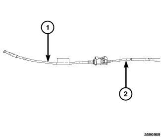
Courtesy of CHRYSLER GROUP, LLC
Turn the ignition off. 1.
2.
Disconnect the (special tool #9977-6-FM, Antenna) from the Radio Antenna harness connector.
3.
Connect the appropriate (special tool #9977-6-4, Jumper) (1) or (special tool #9977-6-2, Jumper) (1) to the Radio Antenna harness connector (2) at the Antenna.
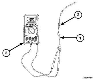
Courtesy of CHRYSLER GROUP, LLC
Disconnect the Radio C3 harness connector.
4. Connect the appropriate (special tool #9977-6-1, Adapter) (1) or (special tool #9977-6-3, Adapter) (1) to the Radio C3 harness connector (2).
6. DIAGNOSIS
5. Measure the resistance across the tool terminals. Is the resistance between 47.5 and 52.5 Ohms?
Yes
1.
The source of the poor reception is not caused by the Radio, Antenna Cable or Radio Antenna.
Perform the BODY VERIFICATION TEST. Refer to STANDARD PROCEDURE . 2. No
Replace the Antenna Cable in accordance with the Service Information. 1. Perform the BODY VERIFICATION TEST. Refer to STANDARD PROCEDURE . 2.
For a complete wiring diagram, refer to appropriate SYSTEM WIRING DIAGRAMS article
DIAGNOSIS AND TESTING > POOR OR NO SATELLITE AUDIO RECEPTION > POSSIBLE CAUSES
Possible Causes
SATELLITE AUDIO ANTENNA CONNECTION
OPEN OR SHORTED SATELLITE AUDIO ANTENNA
SATELLITE AUDIO ANTENNA
RADIO
DIAGNOSIS AND TESTING > POOR OR NO SATELLITE AUDIO RECEPTION >
DIAGNOSTIC TEST
CHECK THE ANTENNA CONNECTION
Turn the ignition off. 1.
Disconnect the Radio C6 harness connector. 2. Inspect the Satellite Audio Antenna harness connection. Is the Antenna connection clean and secure?
Yes
Go To 2 1.
No
Repair the Satellite Audio Antenna connection as needed. 1.
Perform the BODY VERIFICATION TEST. Refer to STANDARD PROCEDURE . 2. 3. 1.
RADIO
Turn the ignition on. 3. Drive the vehicle outside to an un-obstructed area. 4. Turn the Satellite Radio on and select several different known good stations. Is the reception still poor or not available? 5. 2.
Connect the (special tool #9977-6-SAT, Antenna) (1) to the Radio C6 component connector. 1. Place the test antenna base on the roof of the vehicle. 2.
3.
Replace the Radio in accordance with the Service Information. 1.
Perform the BODY VERIFICATION TEST. Refer to STANDARD PROCEDURE . 2. No Go To 3 1.
ANTENNA
Turn the ignition off. 1.
Reconnect the Radio C6 harness connector. 2.
Disconnect the Satellite Audio Antenna harness connector. 3.
4. Turn the Satellite Radio on and select several different known good stations. Is the reception still poor or not available?
Connect the (special tool #9977-6-SAT, Antenna) (1) to the Satellite Audio Antenna harness connector (2).
Perform the BODY VERIFICATION TEST. Refer to STANDARD PROCEDURE . 2. 5.
Yes
Go To 4 1.
No
Replace the Satellite Audio Antenna in accordance with the Service Information. 1.
ANTENNA CABLE 4.
Courtesy of CHRYSLER GROUP, LLC
Turn the ignition off. 1.
3.
2. Connect the appropriate (special tool #9977-6-4, Jumper) (1) or (special tool #9977-6-2, Jumper) (1) to the Satellite Audio Antenna harness connector (2) at the Antenna.
Disconnect the (special tool #9977-6-SAT, Antenna) from the Satellite Audio Antenna harness connector.
Courtesy of CHRYSLER GROUP, LLC
4. Measure the resistance across the tool terminals.
Connect the appropriate (special tool #9977-6-1, Adapter) (1) or (special tool #9977-6-3, Adapter) (1) to the Radio C6 harness connector (2).
5.
Is the resistance between 47.5 and 52.5 Ohms?
Yes
The source of the poor reception is not caused by the Radio, Satellite Antenna Cable or Satellite Antenna. 1.
Perform the BODY VERIFICATION TEST. Refer to STANDARD PROCEDURE . 2. No
Replace the Satellite Audio Antenna Cable in accordance with the Service Information. 1.
Perform the BODY VERIFICATION TEST. Refer to STANDARD PROCEDURE . 2.
DIAGNOSIS AND TESTING > POOR OR NO CELLULAR RECEPTION
CLICK HERE TO DOWNLOAD THE COMPLETE MANUAL
• Thank you very much for reading the preview of the manual.
• You can download the complete manual from: www.heydownloads.com by clicking the link below
• Please note: If there is no response to CLICKING the link, please download this PDF first and then click on it.
CLICK HERE TO DOWNLOAD THE
For a complete wiring diagram, refer to appropriate SYSTEM WIRING DIAGRAMS article
DIAGNOSIS AND TESTING > POOR OR NO CELLULAR RECEPTION > POSSIBLE CAUSES
Possible Causes
CELLULAR ANTENNA CONNECTION
OPEN OR SHORTED CELLULAR ANTENNA CABLES
OPEN OR SHORTED CELLULAR ANTENNA
CELLULAR ANTENNA
RADIO
DIAGNOSIS AND TESTING > POOR OR NO CELLULAR RECEPTION > DIAGNOSTIC TEST
1.
CHECK THE ANTENNA CONNECTION
Turn the ignition off. 1.
Disconnect the Radio C7 harness connector. 2. Inspect the Cellular Antenna harness connection. Is the Antenna connection clean and secure?
Yes
Go To 2 1. No
Repair the Cellular Antenna connection as needed. 1. Perform the BODY VERIFICATION TEST. Refer to STANDARD PROCEDURE . 2. 3.
2.
RADIO
(special tool #9977-6-CELL, Adapter, Cellular Antenna Diagnostic) Connect the (1) to the Radio C7 component connector. 1. Place the test antenna base on the roof of the vehicle. 2. Turn the ignition on. 3.
Drive the vehicle outside to an un-obstructed area. 4. Turn the Radio on. 5.
5. 3.
Is the reception still poor or not available?
Yes
Replace the Radio in accordance with the Service Information. 1.
Perform the BODY VERIFICATION TEST. Refer to STANDARD PROCEDURE . 2. No Go To 3 1.
ANTENNA
Turn the ignition off. 1.
Reconnect the Radio C7 harness connector. 2.
Disconnect the Cellular Antenna harness connector. 3.
4. Turn the Radio on and select several different known good APP/ Cellular functions.
Connect the (special tool #9977-6-CELL, Adapter, Cellular Antenna Diagnostic) (1) to the Radio C7 component connector.
Is the reception still poor or not available?
Yes
Go To 4 1. No
Replace the Cellular Antenna in accordance with the Service Information. 1.
Perform the BODY VERIFICATION TEST. Refer to STANDARD PROCEDURE . 2.
ANTENNA CABLE 4.
Courtesy of CHRYSLER GROUP, LLC
1.
2.
Turn the ignition off.
Connect the (special tool #9977-6-CELL, Adapter, Cellular Antenna Diagnostic) (1) to the Radio C7 component connector.
3.
Connect the appropriate (special tool #9977-6-4, Jumper) (1) or (special tool #9977-6-2, Jumper) (1) to the Cellular Antenna harness connector (2) at the Antenna.
5.
Courtesy of CHRYSLER GROUP, LLC
4. Measure the resistance across the tool terminals. Is the resistance between 47.5 and 52.5 Ohms?
Connect the appropriate (special tool #9977-6-1, Adapter) (1) or (special tool #9977-6-3, Adapter) (1) to the Radio C7 harness connector (2).
Yes
The source of the poor reception is not caused by the Radio, Cellular Antenna Cable or Cellular Antenna. 1.
Perform the BODY VERIFICATION TEST. Refer to STANDARD PROCEDURE . 2. No
Replace the Cellular Antenna Cable in accordance with the Service Information. 1.
Perform the BODY VERIFICATION TEST. Refer to STANDARD PROCEDURE . 2.
DIAGNOSIS AND TESTING > POOR OR NO GPS RECEPTION
For a complete wiring diagram, refer to appropriate SYSTEM WIRING DIAGRAMS article
DIAGNOSIS AND TESTING > POOR OR NO GPS RECEPTION > POSSIBLE CAUSES
Possible Causes
GPS ANTENNA CONNECTION
OPEN OR SHORTED GPS ANTENNA CABLES
OPEN OR SHORTED GPS ANTENNA
GPS ANTENNA
RADIO
DIAGNOSIS AND TESTING > POOR OR NO GPS RECEPTION > DIAGNOSTIC TEST
1.
CHECK THE ANTENNA CONNECTION
Turn the ignition off. 1.
2.
RADIO
3.
Disconnect the Radio C6 harness connector. 2. Inspect the GPS Antenna harness connection.
Is the Antenna connection clean and secure?
Yes
Go To 2 1.
No
Repair the GPS Antenna connection as needed. 1. Perform the BODY VERIFICATION TEST. Refer to STANDARD PROCEDURE . 2.
Connect the (special tool #9977-6-GPS, Adapter, GPS Antenna Diagnostic) (1) to the Radio C6 component connector. 1.
Place the test antenna base on the roof of the vehicle. 2. Turn the ignition on. 3.
Drive the vehicle outside to an un-obstructed area. 4.
Replace the Radio in accordance with the Service Information. 1. 5.
Turn the Satellite Radio on and select several different known good stations.
Is the reception still poor or not available?
Yes
Perform the BODY VERIFICATION TEST. Refer to STANDARD PROCEDURE . 2. No
Go To 3 1.
ANTENNA
Turn the ignition off. 1.
Perform the BODY VERIFICATION TEST. Refer to STANDARD PROCEDURE . 2. 5. 3. ANTENNA CABLE 4.
Reconnect the Radio C6 harness connector. 2.
Disconnect the GPS Antenna harness connector. 3.
4.
Connect the (special tool #9977-6-GPS, Adapter, GPS Antenna Diagnostic) (1) to the Radio C6 component connector.
Turn the Radio on.
Is the reception still poor or not available?
Yes
Go To 4 1. No
Replace the GPS Antenna in accordance with the Service Information. 1.
Courtesy of CHRYSLER GROUP, LLC
1.
2.
Turn the ignition off.
Connect the (special tool #9977-6-GPS, Adapter, GPS Antenna Diagnostic) (1) to the Radio C6 component connector.
3.
Connect the appropriate (special tool #9977-6-4, Jumper) (1) or (special tool #9977-6-2, Jumper) (1) to the GPS Antenna harness connector (2) at the Antenna.
5.
Courtesy of CHRYSLER GROUP, LLC
4. Measure the resistance across the tool terminals. Is the resistance between 47.5 and 52.5 Ohms?
Connect the appropriate (special tool #9977-6-1, Adapter) (1) or (special tool #9977-6-3, Adapter) (1) to the Radio C6 harness connector (2).
Yes
The source of the poor reception is not caused by the Radio, Satellite Antenna Cable or Satellite Antenna. 1.
Perform the BODY VERIFICATION TEST. Refer to STANDARD PROCEDURE . 2. No
Replace the GPS Antenna Cable in accordance with the Service Information. 1.
Perform the BODY VERIFICATION TEST. Refer to STANDARD PROCEDURE . 2.
DIAGNOSIS AND TESTING > DIAGNOSIS AND TESTING REAR CAMERA WITH RRM DISPLAY
For a complete wiring diagram, refer to appropriate SYSTEM WIRING DIAGRAMS article
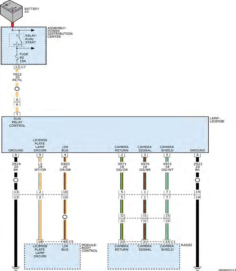
DIAGNOSIS AND TESTING > DIAGNOSIS AND TESTING REAR CAMERA WITH RRM DISPLAY > DIAGNOSIS AND TESTING - REAR CAMERA
CLICK HERE TO DOWNLOAD THE COMPLETE MANUAL
• Thank you very much for reading the preview of the manual.
• You can download the complete manual from: www.heydownloads.com by clicking the link below
• Please note: If there is no response to CLICKING the link, please download this PDF first and then click on it.
CLICK HERE TO DOWNLOAD THE
The hardwired circuits of the Rear View Camera (RVC) and those between the RVC and the Radio Receiver Module (RRM) may be diagnosed using conventional diagnostic tools and procedures. Refer to the appropriate wiring information. The wiring information includes wiring diagrams, proper wire and connector repair procedures, details of wire harness routing and retention, connector pin-out information and location views for the various wire harness connectors, splices and grounds.
However, conventional diagnostic methods will not prove conclusive in the diagnosis of the RVC or the Radio Receiver Module (RRM). The most reliable, efficient and accurate means to diagnose the electronic controls and communication related to Radio Receiver Module (RRM) operation, as well as the retrieval or erasure of a DTC requires the use of a diagnostic scan tool. Refer to the appropriate diagnostic information.
WARNING:
To avoid serious or fatal injury on vehicl es equipped with airbags, disable the Supplemental Restraint System (SRS) before attempting any steering wheel, steering column, airbag, seat belt tensioner, impact sensor, or instrument panel component diagnosis or service. Refer to WARNING . Disconnect and isolate the battery negative (ground) cable, then wait two minutes for the system capacitor to discharge before performing further diagnosis or service. This is the only sure way to disable the SRS. Failure to take the proper precautions could result in accidental airbag deployment.
NOTE:
Before performing tests it is important to check the vehicle sales codes or build configuration to verify if the Tailgate Camera or the optional Center High Mounted Stop Lamp (Chmsl) Camera supplies the image displayed on the Radio (RRM) screen.
NOTE:
Be certain to confirm both of the following prior to attempting any further diagnosis or testing of the RVC. Use a diagnostic scan tool to confirm the rear view camera is setup in the vehicle configuration.
CONDITIONPOSSIBLE CAUSESCORRECTION
NO VIDEO DISPLAY IN RADIODOES NOT DISPLAY CHECK ENTIRE SURROUNDINGS
MESSAGE BRIEFLY AFTER SHIFTING INTO REVERSE
1. Incorrect radio software.
2. Ineffective radio fuse.
3. Ineffective radio ground circuit.
1. Check to be certain that the radio has the latest software update installed. Install the radio software update if required.
2. Test and replace the radio fuses if required.
3. Check for loose or damaged wiring connections at the radio.
NO CAMERA IMAGE IN RADIO VIDEO DISPLAY AND NO BACKUP LAMPS IN REVERSE
4. Ineffective radio feed circuit.
5. Ineffective radio inputs or outputs.
Test and repair the open radio ground circuit if required.
4. Check for loose or damaged wiring connections at the radio. Test and repair the open radio feed circuit if required.
5. Use a diagnostic scan tool to test the radio inputs and outputs including those received over the CAN data bus. Refer to the appropriate diagnostic information.
6. Ineffective radio.
1. Backup lamps inoperative.
6. Use a diagnostic scan tool to test the radio. Refer to the appropriate diagnostic information.
1. Test and repair the open backup lamp switch output circuit between the right and left tail lamps if required.
2. Both backup lamps inoperative.
NO CAMERA IMAGE IN RADIO VIDEO DISPLAY - DOES DISPLAY CHECK ENTIRE SURROUNDINGS MESSAGE BRIEFLY AFTER SHIFTING INTO REVERSE AND BACKUP LAMPS DO OPERATE
3. Ineffective BCM inputs or outputs.
2. Test and repair the open backup lamp switch output circuit between the BODY CONTROL MODULE (BCM) and the tail lamps if required.
3. Use a diagnostic scan tool to test the BCM inputs and outputs. Check Reverse Gear input and check LIN bus voltages to rearview mirror. Refer to the appropriate diagnostic information.
1. Ineffective camera ground circuit.
2. Ineffective camera feed (backup lamp switch output) circuit.
1. Check for loose or damaged wiring connections at the camera, Tailgate light bar and Tailgate. Test and repair the open camera ground circuit if required.
2. Check for loose or damaged wiring connections at the camera, Tailgate light bar and upper Tailgate opening header. Test and repair the open camera feed (backup lamp switch output) circuit if required.
3. Ineffective camera shield circuit.
3. Check for loose or damaged wiring connections at the camera, Tailgate light bar, upper Tailgate
4. Ineffective camera return circuit.
opening header, right cowl side inner panel and radio. Test and repair the open or shorted camera shield circuit if required.
4. Check for loose or damaged wiring connections at the camera, Tailgate light bar, upper Tailgate opening header, right cowl side inner panel and radio. Test and repair the open or shorted camera feed circuit if required.
5. Ineffective camera signal circuit.
6. Ineffective camera.
5. Check for loose or damaged wiring connections at the camera, Tailgate light bar, upper Tailgate opening header, right cowl side inner panel and radio. Test and repair the open or shorted camera signal circuit if required.
6. Replace the ineffective camera if required.
DIAGNOSIS AND TESTING > DIAGNOSIS AND TESTING REAR CAMERA INOPERATIVE WITH RRM DISPLAY
For a complete wiring diagram, refer to appropriate SYSTEM WIRING DIAGRAMS article .
DIAGNOSIS AND TESTING > DIAGNOSIS AND TESTING REAR CAMERA INOPERATIVE WITH RRM DISPLAY > THEORY OF OPERATION
The Camera is activated when the ignition switch is in the RUN position. The (F923) circuit supplies power to the camera. The camera sends a video signal (std. NTSC i.e. TV) to the Radio Receiver
Module (RRM), using circuits (X970) camera signal, (X971) signal return and (X972) camera shield, which displays on the Radio Receiver Module (RRM) screen. The screen toggles functions displaying only one kind of image at a time. And in reverse, the rear camera has priority. The (Z923) circuit is ground for the system.
DIAGNOSIS AND TESTING > DIAGNOSIS AND TESTING REAR CAMERA
INOPERATIVE WITH RRM DISPLAY > WHEN MONITORED
Ignition on, vehicle in reverse.
DIAGNOSIS AND TESTING > DIAGNOSIS AND TESTING REAR CAMERA
INOPERATIVE WITH RRM DISPLAY > SET CONDITION
No rear picture is displayed on Radio Receiver Module (RRM) with the vehicle in reverse.
DIAGNOSIS AND TESTING > DIAGNOSIS AND TESTING REAR CAMERA
INOPERATIVE WITH RRM DISPLAY > POSSIBLE CAUSES
Possible Causes
(F923) FUSED RUN RELAY OUTPUT CIRCUIT
(Z923) GROUND CIRCUIT
(X970) CAMERA SIGNAL CIRCUIT
(X971) CAMERA RETURN CIRCUIT
(X972) CAMERA SHIELD
REAR VIDEO CAMERA ASSEMBLY
DIAGNOSIS AND TESTING > DIAGNOSIS AND TESTING REAR CAMERA
INOPERATIVE WITH RRM DISPLAY > DIAGNOSTIC TEST
VERIFY OPERATION OF THE RADIO AND BACKUP LAMPS
Verify the operation of the Radio and Backup Lamps.
Do the Radio and Backup Lamps operate correctly?
2.
Diagnose any problems with the Radio and Backup Lamps. 1.
Perform the BODY VERIFICATION TEST. Refer to STANDARD PROCEDURE . 2.
CHECK THE (F923) FUSED RUN RELAY OUTPUT CIRCUIT
Turn the ignition off. 1. Apply the parking brake. 2.
Disconnect the Rear Video Camera Assembly Harness Connector. 3.
Turn the ignition on. 4.
5.
Measure the voltage between the (F923) Fused Run Relay Output circuit and ground.
Is battery voltage present?
Yes
Go To 3 1.
No
Repair the (F923) Fused Run Relay Output circuit for an open or short to ground. 1.
Perform the BODY VERIFICATION TEST. Refer to STANDARD PROCEDURE . 2.
3.
CHECK THE (Z923) GROUND CIRCUIT
Turn the ignition off. 1.
2.
Measure the resistance between ground and the (Z923) Ground Circuit.
Is the resistance below 5.0 Ohms?
Yes
Go To 4 1. No
Repair the (Z923) Ground circuit for an open. 1.
Perform the BODY VERIFICATION TEST. Refer to STANDARD PROCEDURE . 2.
4.
CHECK THE (X970) CAMERA SIGNAL, THE (X971) RETURN, AND THE (X972) SHIELD CIRCUITS FOR AN OPEN CIRCUIT
Disconnect the Radio C1 harness connector. 1.
Yes 2.
Measure the resistance of the (X970) (X971) and (X972) circuits between the Rear Camera harness connector and Radio C1 harness connectors.
Is the resistance below 5.0 Ohms on the (X970) (X971) or (X972) circuits?
5.
Go To 5 1.
No
Repair the appropriate circuit for an open. 1.
Perform the BODY VERIFICATION TEST. Refer to STANDARD PROCEDURE . 2.
CHECK THE (X970) CAMERA SIGNAL, THE (X971) RETURN, AND THE (X972) SHIELD CIRCUITS SHORTED TO GROUND
Measure the resistance between ground and the (X970) (X971) and (X972) circuits. Is the resistance below 5.0 Ohms on the (X970) (X971) or (X972) circuits?
Yes
Repair the appropriate circuit for a short to ground. 1.
Perform the BODY VERIFICATION TEST. Refer to STANDARD PROCEDURE . 2. No
Replace the Rear Camera Assembly in accordance with the Service Information. 1.
Perform the BODY VERIFICATION TEST. Refer to STANDARD PROCEDURE . 2.
DIAGNOSIS AND TESTING
KIT
The MIT019 Multi-Media Test kit includes the tester, power outlet adaptor and a set of test tip cards. The MIT019 can be updated by connecting to any computer using the USB connector on the tester. The updates are supported through DealerConnect tech support. If the test cards are lost, a new set can be downloaded from the tool by connecting to any supporting computer. The test card information in the tool can be downloaded in one of 3 languages: English, Spanish or French.
TO DOWNLOAD THE TEST CARD INFORMATION:
1.
Connect the MIT019 to a USB port on a computer (which will power the tool and display the current software version).
Press the USB button on the MIT019. 2.
Once the computer recognizes the MIT019, it will display 3 files available. 3.
Select the file named "MANUAL". 4.
Download the section required to create the test cards needed. 5.
FOR UPDATES:
1.
While holding down the zero button on the MIT019, connect the MIT019 to a USB port on a computer (which will power the tool and display the current software version).
2.
If you are a Chrysler Group LLC Dealership, visit: https://dealerconnect.chrysler.com.
If you are a Non-Chrysler Group LLC Dealership, visit: www.techauthority.com. 3.
Locate the MIT019 software update page (verify that a newer software version is available). 4. Download the update file and run the.exe file. 5.
Follow the on-screen instructions to install the update. 6.
7.
Disconnect the MIT019 USB connection from the computer and the tool is ready to use.
DIAGNOSIS AND TESTING > MIT019 MULTI-MEDIA TESTER > MIT019 MULTI-MEDIA TESTER FUNCTIONALITY
The MIT019 Multi-Media Test kit was developed to help diagnose customer concerns with features of the Multi-Media systems in their vehicles. The purpose of this tool is to simulate the following:
A known good cell phone
A known good media source (Ipod®, Ipad®, or MP3 players)
Using this tester will determine if the cause of concern is related to a vehicle system concern or the customer`s device being used.
The MIT019 can be used to perform 7 different tests of specific operations:
Operation of the AUX port 1.
Operation of the USB port for both power and Audio input concerns 2.
Bluetooth phone pairing 3.
Bluetooth hands free calling (send & receive) phone book push test 4.
Bluetooth streaming audio 5.
Bluetooth SMS messaging - send 6.
Bluetooth SMS messaging - receive 7.
NOTE:
When testing functions of the audio/media system, it is important to verify whether or not the vehicle is equipped with an internal or external Hands Free Module. In some cases the external Hands Free Module controls the operation of the external AUX and USB ports along with the Uconnect functions.
It is important to determine what system features are supported by the audio system in the customer's vehicle and device. For information on the operation and supported features of the vehicle's media system, refer to the flowing websites:
Vehicle websites available to customers and dealership personnel:
http://www.dodge.com/en/uconnect
http://www.chrysler.com/en/uconnect
http://www.jeep.com/en/uconnect
http://www.ramtrucks.com/en/uconnect
http://www.fiatusa.com/en/BlueAndMe
http://www.driveuconnect.com
Vehicle information support websites for dealership personnel only:
DealerConnect
STAR cases
Technical Service Bulletins
wiTECH for radio updates
The MIT019 was designed to test the following Radio/Multi-Media systems:
2010 - present NTG4 Radio/Multi-Media systems
2011 - present PowerNet Radio/Multi-Media systems
2013 - present RRM Radio/Multi-Media systems
DIAGNOSIS AND TESTING > MIT019 MULTI-MEDIA TESTER > MIT019 FUNCTIONALITY TESTS
BELOW ARE THE 7 FUNCTIONALITY TESTS AVAILABLE USING THE MIT019 MULTI-MEDIA TESTER:
Go To 2 1. 1.
AUXILIARY INPUT JACK TEST
Go To 3 1. 2. BLUETOOTH PAIRING
USB INPUT/OUTPUT TEST
Go To 4 1. 3.
BLUETOOTH HANDS FREE CALLING/PHONEBOOK PUSH TEST
Go To 5 1.
BLUETOOTH STREAMING AUDIO TEST
CLICK HERE TO DOWNLOAD THE COMPLETE MANUAL
• Thank you very much for reading the preview of the manual.
• You can download the complete manual from: www.heydownloads.com by clicking the link below
• Please note: If there is no response to CLICKING the link, please download this PDF first and then click on it.
CLICK HERE TO DOWNLOAD THE
Go To 6 1.
6.
BLUETOOTH SMS MESSAGING - SEND
Go To 7 1.
7.
BLUETOOTH SMS MESSAGING - RECEIVE
Go To 8 1.
AUXILIARY INPUT JACK TEST
Check the Multi-Media ports for damaged connection points or debris in the 2. 3. 2.
NOTE:
This test is designed to validate the ability of the Audio/Media system to play audio from a customer's device that has been connected to the AUX port on the radio or externally through a UCI (Universal Customer Interface / Multi-Media) port.
NOTE:
The AUX port cannot supply power to a connected device.
Connect the USB and Auxiliary Cable into the vehicle's audio ports. 1. Verify the MIT019 is in AUX Mode. 2.
Using the vehicle controls, place the audio system into AUX (Line In) Mode. (Audio system may automatically enter into AUX Mode.)
Does the Radio play audio from the MIT019?
Yes
Audio playback confirms that the Auxiliary Input is working correctly, no system repairs are needed at this time. 1.
Check the condition of the customer`s cords and device being used. 2.
Check to make sure the customer`s device and cables are compatible with the vehicle system. 3.
Check the customer`s device for output and volume setting concerns. 4.
Check for updates for the customer`s device relating to the customer`s concern. 5. No
If Audio playback does not occur, refer to the appropriate Service Information. Refer to DIAGNOSIS AND TESTING . 1.
ports.
Check wiring circuits and connections to the AUX port for concerns. 3.
4.
Check for vehicle related system updates, STAR cases and TSBs related to the customer`s concern.
If no updates are available for the concern, replace the Radio or Hands Free Module in accordance with the Service Information. 5.
USB INPUT/OUTPUT TEST
NOTE:
This test is designed to validate the ability of the Audio/Media system to play audio from a customer's device that has been connected to the USB port on the radio or the external USB port (Universal Customer Interface (UCI) / Multi- Media port). By connecting the MIT019 to the USB ports it will also determine if the USB port can provide power to a connected device.
3. 3.
1. Place the MIT019 into USB Mode.
Connect the USB Cable into the vehicle's USB port.
2.
Using the vehicle controls, place the audio system into USB Mode. (Audio system may automatically enter into USB Mode.)
Does the Radio play audio from the MIT019?
Yes
1.
Audio playback confirms that the USB Input is working correctly, no system repairs are needed at this time.
Check the condition of the customer`s cords and device being used. 2.
3.
Check to make sure the customer`s device and cables are compatible with the vehicle system.
Check the customer`s device for output and volume setting concerns. 4.
Check for updates for the customer device relating to the customer`s concern. 5. No
1.
If Audio playback does not occur, refer to the appropriate Service Information. Refer to DIAGNOSIS AND TESTING .
2.
Check the Multi-Media ports for damaged connection points or debris in the ports.
Check wiring circuits and connections to the USB port for concerns. 3.
Check for vehicle related system updates, Star online cases and TSBs related to the customers concern. 4.
5.
If no updates are available for the concern, replace the Radio or Hands Free Module in accordance with the Service Information.
NOTE:
The radio and external USB ports can only supply 5 volts at 500 mAs. Check to see what the customer's device requires for operation or charging. Some vehicles are equipped with a standalone USB charging port that can supply 5 volts at 1.5 amps. For more information on system operation and supported features see the vehicle supporting website "For Owners Page" or the h ttp://www.driveuconnect.com.
BLUETOOTH PAIRING
Before testing it is important to check the total number of devices paired to the vehicles system. Each system has a limit to the number of items that can be paired to the system. For more information on system operation and supported features see the vehicle supporting website "For Owners Page" or the Driveuconnect website at http://www.driveuconnect.com. 4.
NOTE:
This test is designed to validate the pairing ability of the vehicles Audio/Media system. Pairing the MIT019 to the vehicle system will simulate the use of a known good compatible phone to test the system operation.
NOTE:
NOTE:
If the customer`s concern is the vehicle system was working with their device but then stopped working correctly, verify and perform the following:
Check to see if the device was recently updated. 1. Clear the device pairing from the system. 2.
3.
Reboot the customer`s device.
Re-pair the device to the vehicle system. 4. Check the operation. 5.
At times, cell providers will update the software or firmware in the customer`s device (without the customer knowing) causing it to become out of sync with the vehicle`s system.
NOTE:
During this test, use the power outlet adaptor supplied with the MIT019 Multi-Media Test kit to supply the power and ground to the tester. This will confirm and demonstrate the Bluetooth connection without anything connected to the Audio/Media system ports.
NOTE:
In order for the tool to function correctly, first plug the MIT019 power supply adapter into the 12 volt power outlet receptacle and confirm adapter power LED illuminates. Then connect the MIT019 to the power supply adapter.
1.
Connect the power outlet power adapter into the 12 volt receptacle.
2. Place the MIT019 into Bluetooth Mode.
Connect the USB Cable into the Power Outlet Power Adapter. (This assists in showing the customer that the tool is utilizing a Bluetooth connection.)
3.
Use the vehicle audio controls to place the audio system into ready to PAIR Mode. (Audio system may automatically enter into Bluetooth Mode.)
4. Press the PAIR button on the MIT019 the unit will identify the Vehicle Audio System.
5.
6.
When prompted, enter the Pairing Pin number on the MIT019 then press enter. The MIT019 will Pair and Connect to the vehicle audio system. Does the MIT019 pair to the Audio/Media system?
5.
1.
If the MIT019 pairs to the system, the Hands Free connection is working correctly, no part replacement is needed
2.
3.
Check the total number of devices paired to the customer`s device.
Check to make sure the customer`s device and cables are compatible with the vehicle system.
4.
Check to see if the customer`s device supports the vehicle feature being tested.
Check the customer`s device for concerns related to password locks, phone book transfer settings and data transfer locks/settings.
5. For more information on system operation and supported features see the vehicle supporting website "For Owners Page" or the Driveuconnect website at http://www.driveuconnect.com.
6. No
If Pairing does not occur, refer to the appropriate Service Information. Refer to DIAGNOSIS AND TESTING .
2.
1. Check for vehicle related system updates, STAR cases and TSBs related to the customers concern.
3.
If no updates are available for the concern, replace the Radio or Hands Free Module in accordance with the Service Information.
BLUETOOTH HANDS FREE CALLING / PHONE BOOK PUSH TEST
NOTE:
This test is designed to validate the ability of the Audio/Media system to place and receive phone calls. The MIT019 will change the radio display to show "MULTI-MEDIA TESTER" to confirm the phone-book-push was successful.
NOTE:
Before testing it is important to check the total number of devices paired to the vehicles system. Each system has a limit to the number of items that can be paired to the system. For more information on system operation and supported features see the vehicle supporting website "For Owners Page" or the Driveuconnect website at http://www.driveuconnect.com.
NOTE:
If the customer`s concern is the vehicle system was working with their device but
then stopped working correctly, verify and perform the following:
Check to see if the device was recently updated. 1. Clear the device pairing from the system. 2. Reboot the customer`s device. 3. Re-pair the device to the vehicle system. 4. Check the operation. 5.
At times, cell providers will update the software or firmware in the customer`s device (without the customer knowing) causing it to become out of sync with the vehicle`s system.
NOTE:
During this test use the Power outlet adaptor supplied with the MIT019 Multi-Media Test kit to supply the power and ground to the tester. This will confirm and demonstrate the Bluetooth connection without anything connected to the Audio/Media system ports.
NOTE:
In order for the tool to function correctly, first plug the MIT019 power supply adapter into the 12 volt power outlet receptacle and confirm adapter power LED illuminates. Then connect the MIT019 to the power supply adapter.
Be sure the MIT019 is properly paired. 1.
From MIT019 in Bluetooth Mode, press the CALL button. 2. The vehicle should announce an incoming call. 3. The media system will display "MULTI-MEDIA TESTER", confirming successful push of the phone book.
4. Using the vehicle controls, answer the call. 5.
6. Using the vehicle controls, end the call.
Audio playback will confirm the Hands Free connection is working correctly, no system part replacement is needed.
Yes 7.
Does the Media system playback the incoming audio and display "MULTI-MEDIA TESTER"?
6.
1. Check the total number of devices paired to the customer`s device.
3.
If Audio playback occurs and the system displays "MULTI-MEDIA TESTER", the system is working correctly; no part replacement is needed.
2. Check to make sure the customer`s device and cables are compatible with the vehicle system.
4.
Check to see if the customer`s device supports the feature that the customer is trying to use.
Check the customer`s device for concerns related to password locks, phone book transfer settings and data transfer locks/settings.
5. For more information on system operation and supported features see the vehicle supporting website "For Owners Page" or the Driveuconnect website at http://www.driveuconnect.com.
6. No
1.
If Audio playback does not occur, reference appropriate Service Information. Refer to DIAGNOSIS AND TESTING .
2. If no updates are available for the concern, replace the Radio or Hands Free Module in accordance with the Service Information.
Check for vehicle related system updates, STAR cases and TSBs related to the customers concern.
3. BLUETOOTH STREAMING AUDIO TEST
NOTE:
This test is designed to validate the ability of the Audio/Media system to play streamed audio by a Bluetooth connected device.
NOTE:
Before testing it is important to check the total number of devices paired to the vehicles system. Each system has a limit to the number of items that can be paired to the system. For more information on system operation and supported features see the vehicle supporting website "For Owners Page" or the Driveuconnect website at http://www.driveuconnect.com.
NOTE:
If the customer`s concern is the vehicle system was working with their device but then stopped working correctly, verify and perform the following:
Check to see if the device was recently updated. 1. Clear the device pairing from the system. 2. Reboot the customer`s device.
3. Re-pair the device to the vehicle system. 4. Check the operation. 5.
At times, cell providers will update the software or firmware in the customer`s device (without the customer knowing) causing it to become out of sync with the vehicle`s system.
NOTE:
During this test use the Power outlet adaptor supplied with the MIT019 Multi-Media Test kit to supply the power and ground to the tester. This will confirm and demonstrate the Bluetooth connection without anything connected to the Audio/Media system ports.
NOTE:
In order for the tool to function correctly, first plug the MIT019 power supply adapter into the 12 volt power outlet receptacle and confirm adapter power LED illuminates. Then connect the MIT019 to the power supply adapter.
Connect the power outlet power adapter into the 12 volt receptacle. 1.
2. Be sure the MIT019 is properly paired.
Connect the USB Cable into the Power Outlet Power Adapter. (This assists in showing the customer that the tool is utilizing a Bluetooth connection.)
3. Leave the MIT019 in Bluetooth Audio Mode after pairing is complete. 4.
Using the vehicle controls, place the audio system into Bluetooth Audio. Does the Radio play audio from the MIT019?
Check to make sure the customer`s device and cables are compatible with the vehicle system. 3. 5.
Yes
1. Check the total number of devices paired to the customer`s device. 2.
Audio playback will confirm that the Bluetooth Streaming Audio is working correctly, no system part replacement is needed.
7.
4.
Check to see if the customer`s device supports the vehicle feature being tested.
Check the customer`s device for concerns related to password locks, phone book transfer settings and data transfer locks/settings.
5. For more information on system operation and supported features see the vehicle supporting website "For Owners Page" or the Driveuconnect website at http://www.driveuconnect.com.
6. No
1.
If Audio playback does not occur, refer to the appropriate Service Information. Refer to DIAGNOSIS AND TESTING .
2.
Check for vehicle related system updates, STAR cases and TSBs related to the customers concern.
3.
If no updates are available for the concern, replace the Radio or Hands Free Module in accordance with the Service Information.
BLUETOOTH SMS MESSAGING- RECEIVE
NOTE:
This test is designed to validate the ability of the Audio/Media system to receive a SMS message.
NOTE:
Before testing it is important to check the total number of devices paired to the vehicles system. Each system has a limit to the number of items that can be paired to the system. For more information on system operation and supported features see the vehicle supporting website "For Owners Page" or the Driveuconnect website at http://www.driveuconnect.com.
NOTE:
If the customer`s concern is the vehicle system was working with their device but then stopped working correctly, verify and perform the following:
Check to see if the device was recently updated. 1. Clear the device pairing from the system. 2. Reboot the customer`s device. 3. Re-pair the device to the vehicle system. 4. Check the operation. 5.
CLICK HERE TO DOWNLOAD THE COMPLETE MANUAL
• Thank you very much for reading the preview of the manual.
• You can download the complete manual from: www.heydownloads.com by clicking the link below
• Please note: If there is no response to CLICKING the link, please download this PDF first and then click on it.
CLICK HERE TO DOWNLOAD THE
At times, cell providers will update the software or firmware in the customer`s device (without the customer knowing) causing it to become out of sync with the vehicle`s system.
NOTE:
During this test use the Power outlet adaptor supplied with the MIT019 Multi-Media Test kit to supply the power and ground to the tester. This will confirm and demonstrate the Bluetooth connection without anything connected to the Audio/Media system ports.
NOTE:
In order for the tool to function correctly, first plug the MIT019 power supply adapter into the 12 volt power outlet receptacle and confirm adapter power LED illuminates. Then connect the MIT019 to the power supply adapter.
Connect the Power outlet Power Adapter into the 12 volt receptacle. 1.
2.
Connect the USB Cable into the Power Outlet Power Adapter. (This assists in showing the customer that the tool is utilizing a Bluetooth connection.)
Be sure the MIT019 is properly paired. 3.
From Bluetooth Mode, press the SMS button. 4. MIT019 will send a new message to the vehicle audio system. 5. The vehicle audio system will confirm the receipt of a new message. 6.
Using the vehicle controls, retrieve the message to verify proper functionality. Does the Radio display the message "MULTI-MEDIA TESTER" from the MIT019?
Check the customer`s device for concerns related to password locks, phone book transfer settings and data transfer locks/settings. 5. For more information on system operation and supported features see the 6. 7.
Yes
If functioning correctly, no system part replacement is needed. 1.
Check the total number of devices paired to the customer`s device. 2.
Check to make sure the customer`s device and cables are compatible with the vehicle system. 3.
Check to see if the customer`s device supports the vehicle feature being tested. 4.
vehicle supporting website "For Owners Page" or the Driveuconnect website at http://www.driveuconnect.com.
If the Audio system does not display the new message, reference the appropriate Service Information on system operation and supported features. See the vehicle supporting website "For Owners Page" or the Driveuconnect website at http://www.driveuconnect.com.
2.
1. Check for vehicle related system updates, STAR cases and TSBs related to the customers concern.
If no updates are available for the concern, replace the Radio or Hands Free Module in accordance with the Service Information.
NOTE:
This test is designed to validate the ability of the Audio/Media system to send a SMS message from the list of preset messages.
NOTE:
Before testing it is important to check the total number of devices paired to the vehicles system. Each system has a limit to the number of items that can be paired to the system. For more information on system operation and supported features see the vehicle supporting website "For Owners Page" or the Driveuconnect website at http://www.driveuconnect.com.
NOTE:
If the customer`s concern is the vehicle system was working with their device but then stopped working correctly, verify the following:
Check to see if the device was recently updated. 1. Clear the device pairing from the system. 2.
Reboot the customer`s device. 3.
Re-pair the device to the vehicle system. 4.
Check the operation. 5.
At times, cell providers will update the software or firmware in the customer`s device (without the customer knowing) causing it to become out of sync with the vehicle`s system.
NOTE:
During this test use the Power outlet adaptor supplied with the MIT019 Multi-Media Test kit to supply the power and ground to the tester. This will confirm and demonstrate the Bluetooth connection without anything connected to the Audio/Media system ports.
NOTE:
In order for the tool to function correctly, first plug the MIT019 power supply adapter into the 12 volt power outlet receptacle and confirm adapter power LED illuminates. Then connect the MIT019 to the power supply adapter.
Connect the power outlet power adapter into the 12 volt receptacle. 1.
2.
Connect the USB Cable into the Power Outlet Power Adapter. (This assists in showing the customer that the tool is utilizing a Bluetooth connection.)
3.
Be sure the MIT019 is properly paired.
Using the vehicle controls, send a text message. 4.
If functioning correctly, no system part replacement is needed. 1. 5.
The MIT019 will display the chosen message. Does the MIT019 Multi-Media Tester display on the tool the message sent by the Multi-Media system?
Yes
2.
3.
Check the total number of devices paired to the customer`s device.
Check to make sure the customer`s device and cables are compatible with the vehicle system.
4.
Check to see if the customer`s device supports the vehicle feature being tested.
Check the customer`s device for concerns related to password locks, phone book transfer settings and data transfer locks/settings.
5. For more information on system operation and supported features see the vehicle supporting website "For Owners Page" or the Driveuconnect website at http://www.driveuconnect.com.
6. No
If the MIT019 does not display the new message, reference the appropriate Service Information on system operation and supported features. See the vehicle supporting website "For Owners Page" or the Driveuconnect website at http://www.driveuconnect.com.
2.
1. Check for vehicle related system updates, STAR cases and TSBs related to the customers concern.
3.
If no updates are available for the concern, replace the Radio or Hands Free Module in accordance with the Service Information.
DESCRIPTION > DESCRIPTION
Several combinations of radio receivers and speaker configurations are offered. The audio system uses an ignition switched source of battery current so that the system will only operate when the ignition switch is in the RUN or ACCESSORY positions.
The radios can be identified by sales code RA2, RA3, and RA4. An optional navigation radio (RA4) is available on this vehicle. For more information, see DESCRIPTION .
The RA2, RA3, and RA4 radios all have an internal Hands Free Module (HFM). There is no external HFM because all hands free functions are integrated into the head unit.
The audio system includes the following components:
Antenna (radio, satellite, GPS, cellular)
Power amplifier (with premium audio systems only) - Refer to AMPLIFIER, DESCRIPTION .
Radio noise suppression components - Refer to COMPONENTS, RADIO NOISE SUPPRESSION, DESCRIPTION .
Radio Receiver Module (RRM) - Refer to RADIO, DESCRIPTION .
Remote radio switches (if equipped) - Refer to SWITCH, REMOTE RADIO, OPERATION .
Speakers - Refer to SPEAKER, DESCRIPTION .
Media Hub - Refer to MEDIA HUB, DESCRIPTION .
Certain functions and features of the audio system rely upon resources shared with other electronic modules in the vehicle over the Controller Area Network (CAN-IHS) bus network. The data bus network allows the sharing of sensor information. For diagnosis of these electronic modules or of the data bus network, the use of a scan tool and the proper Diagnostic Procedures information is recommended.
OPERATION > OPERATION
The audio system components are designed to provide audio entertainment and information through the reception, tuning and amplification of locally broadcast or satellite, (if equipped) radio signals in both the Amplitude Modulating (AM) and Frequency Modulating (FM) commercial frequency ranges.
The audio system components operate on battery current received through a fuse in the Power Distribution Center (PDC) on a fused ignition switch output (run-acc) circuit so that the system will only operate when the ignition switch is in the Run or Accessory positions.
The optional navigation radio system receives GPS signals from up to eight satellites to display the position and direction of the vehicle. Map information is supplied through a DVD-ROM. An electronic gyro-sensor and the vehicle's speed sensor enable the system to display the present vehicle position even in locations where GPS signals may be blocked.
When a destination is selected, the navigation system uses information from the map to quickly
calculate a route. As the vehicle is driven along the chosen route, the operator is guided with pictorial displays and voice prompts.
On vehicles that are equipped with the optional remote radio switches, the Body Control Module (BCM) receives the input from the SCCM. The inputs are sent over the LIN from the remote radio switches to the SCCM. The programming in the BCM allows it to process those inputs and send the proper messages to the radio receiver over the CAN IHS network to control the radio volume up or down, station seek up or down, preset station advance, and mode advance functions.
DIAGNOSIS AND TESTING > VIDEO
VIDEO SYSTEM DIAGNOSIS
CONDITIONPOSSIBLE CAUSESCORRECTION
NO VIDEO (DVD PLAYER WILL NOT LOAD OR EJECT FROM RADIO)
1. Fuse inoperative.1. Check fuses. Replace fuses if required.
2. Loose or damaged radio connector
2. Check for loose or corroded radio connector. Repair or replace as required.
3. Ground connection damaged3. Check for continuity between radio and a known good ground. There should be continuity. Repair ground if required.
4. Radio damaged4. Exchange or replace radio if required.
5. DVD damaged.
NOTE:
Avoid using CD's or DVD's that have adhesive type labels, as they may cause the disc to become jammed.
5. Insert known good DVD and test operation.
NO DISPLAY. AUDIO HEARD THROUGH SPEAKERS
1. Loose or damaged connectors
1. Check for loose or corroded radio connector. Check for loose or corroded video screen connector. Repair if required. Check for loose or damaged in-line connector.
2. Wiring damaged2. With harness connected, check for video signal voltage at radio and at video screen harness. Place known good DVD into the radio. Place positive lead of voltmeter on video signal of the connector. Place negative lead on video ground. Readings should be between
0.1v to 2v dc.
3. Video screen damaged3. Exchange or replace video screen if required.
WHITE DISPLAY1. Low voltage1. Check for battery voltage (9v-16v) at the radio. Display will be white if voltage drops below 6v.
DARK OR BRIGHT SPOTS ON SCREEN
2. Video screen damaged2. Exchange or replace video screen if required.
1. Brightness setting requires adjustment.
BRIGHT OR DARK DISPLAY
1. Video screen display pixel defect.
1. Adjust brightness setting of video screen by pressing buttons on side of video screen until desired level is reached. Start with a black screen, then press button up 16-20 times. There are 64 total steps of brightness.
1. The acceptable level of dots on the screen is (green-1, red-2) or a total (green+red+blue+white+black) = 8. Replace or exchange video screen if necessary.
VIDEO SELECTIONS DO NOT APPEAR FULL SCREEN WIDTH
1. Aspect ratio is set incorrectly.1. Using mode button, adjust until video appears correctly.
2. Some DVD's are two sided. One side is wide screen format and the other is full screen or there may be a wide screen or standard screen format on the disc.
2. Ensure that DVD is inserted correctly.
BUTTONS ON VIDEO SCREEN INOPERATIVE
1. Video screen damaged.1. Place known good DVD into radio. Once image appears on video screen, press top button on side of video screen to adjust width of display. Press bottom buttons to adjust brightness. Once DVD menu appears on video screen, press middle button on video screen. Highlighted selection will begin to play. If any of the buttons do not function, replace or exchange video screen.
DIAGNOSIS AND TESTING > DIAGNOSIS AND TESTING - AUDIO
Any diagnosis of the audio system should begin with the use of a diagnostic scan tool. Check for any Diagnostic Trouble Code (DTC) data. If a DTC is found, refer to DIAGNOSTIC CODE INDEX and perform the appropriate diagnostic procedure before proceeding in this service information . Refer to the appropriate wiring information.
WARNING:
To avoid serious or fatal injury on vehicl es equipped with airbags, disable the Supplemental Restraint System (SRS) before attempting any steering wheel, steering column, airbags, airbag curtains, knee blocker, seat belt tensioner, impact sensor or instrument panel component diagnosis or service. Disconnect the IBS/negative battery cable assembly from the negative battery post, then wait two minutes for the system capacitor to discharge before performing further diagnosis or service. This is the only sure way to disable the SRS. Failure to take the proper precautions could result in accidental airbag deployment.
AUDIO SYSTEM DIAGNOSTIC TABLE
CONDITIONPOSSIBLE CAUSESCORRECTION
1. Fuse inoperative.Check radio fuse.
RADIO INOPERATIVE
NO AUDIO - BUT RADIO LIGHTS UP
2. Open wiring.
Check "No Response from Radio". Refer to DIAGNOSIS AND TESTING .
1. Antenna problem.Perform the "Poor or No AM/FM Audio Reception" test. Refer to DIAGNOSIS AND TESTING .
2. Radio or Amplifier (if equipped) connector damaged.
Check for loose or corroded radio/amplifier connector. Repair, as required.
3. Wiring damaged.Check for shorted or open wires. Repair wiring as required.
4. Radio or Amplifier (if equipped) ground damaged.
5. Amplifier (if equipped) inoperative.
Check for continuity between radio chassis and a known good ground. There should be continuity. Repair ground as required.
For Base, refer to DIAGNOSTIC CODE INDEX . For Premium, refer to DIAGNOSTIC CODE INDEX .
6. Speakers inoperative.Refer to DIAGNOSIS AND TESTING .
NO RADIO DISPLAY1. Fuse inoperative.Check radio fuse, Replace fuses as required.
2. Radio connector damaged.
Check for loose or corroded radio connector. Repair as required.
3. Wiring damaged.Check for battery voltage at radio connector. Repair wiring as required.
4. Radio ground circuit damaged.
Check for continuity between radio chassis and a known good ground. There should be continuity. Repair ground as required.
5. Radio inoperative.Check "No Response from Radio". Refer to DIAGNOSIS AND TESTING .
POOR AM/FM RADIO RECEPTION
POOR SDAR AUDIO RECEPTION
SOUND DISTORTION (VIBRATION FROM SPEAKER AREA, BUZZINGHUMMING)
6. Center stack screenRefer to DIAGNOSIS AND TESTING .
1. Antenna inoperative.Perform the "Poor or No AM/FM Audio Reception" test. Refer to DIAGNOSIS AND TESTING .
2. Radio ground damaged.Check for continuity between radio chassis and a known good ground. There should be continuity. Repair ground as required.
3. Radio inoperative.Refer to DIAGNOSIS AND TESTING or DIAGNOSIS AND TESTING .
1. SDAR antenna Inoperative.
1. Door trim panel loose or missing fasteners.
2. Water shield loose or misaligned.
3. Items placed in door trim panel map pockets vibrating or moving from side to side.
AMPLIFIER > DESCRIPTION > DESCRIPTION
Perform the "Poor or No Satellite Audio Reception" test. Refer to DIAGNOSIS AND TESTING .
Inspect door trim panel and correct as necessary. Replace any missing fasteners.
Inspect water shield and adjust as required.
Remove items from door trim panel. Ensure that vibration is no longer present.
CLICK HERE TO DOWNLOAD THE COMPLETE MANUAL
• Thank you very much for reading the preview of the manual.
• You can download the complete manual from: www.heydownloads.com by clicking the link below
• Please note: If there is no response to CLICKING the link, please download this PDF first and then click on it.
CLICK HERE TO DOWNLOAD THE
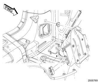
Courtesy of CHRYSLER GROUP, LLC
Vehicles equipped with the Premium Alpine System package have a separate amplifier unit. The amplifier is rated at 506 watts. The amplifier is mounted to the left rear quarter panel behind the quarter trim panel.
AMPLIFIER > DIAGNOSIS AND TESTING > DIAGNOSIS AND TESTING - AMPLIFIER
Any diagnosis of the Audio system should begin with the use of a scan tool and the appropriate Diagnostic Service information.
For complete circuit diagrams, refer to SYSTEM WIRING DIAGRAMS .
The amplifier unit should be checked if there is no sound output noted from the speakers. For diagnosis of the power amplifier, refer to SPEAKER, DIAGNOSIS AND TESTING .
AMPLIFIER > REMOVAL > REMOVAL
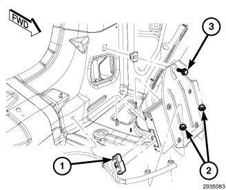
Courtesy of CHRYSLER GROUP, LLC
Disconnect and isolate the battery negative cable. 1. Remove the left quarter trim panel. Refer to PANEL, QUARTER TRIM, REMOVAL . 2.
Disconnect the two wire harness connectors (1) from the amplifier. 3. Remove the mounting fasteners (2) (3). 4. Remove the amplifier. 5.
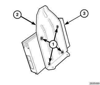
Courtesy of CHRYSLER GROUP, LLC
Remove the retainers (1) from the amplifier bracket (2). 6.
AMPLIFIER > INSTALLATION > INSTALLATION
Courtesy of CHRYSLER GROUP, LLC
Install the retainers (1) to the amplifier and amplifier bracket (2). 1.
Courtesy of CHRYSLER GROUP, LLC
2.
Position the amplifier into place.
3.
Install and tighten the mounting fasteners (2) (3).
Connect the two wire harness connectors (1).
4. Install the left quarter trim panel. Refer to PANEL, QUARTER TRIM, INSTALLATION .
5.
6.
Connect the battery negative cable.
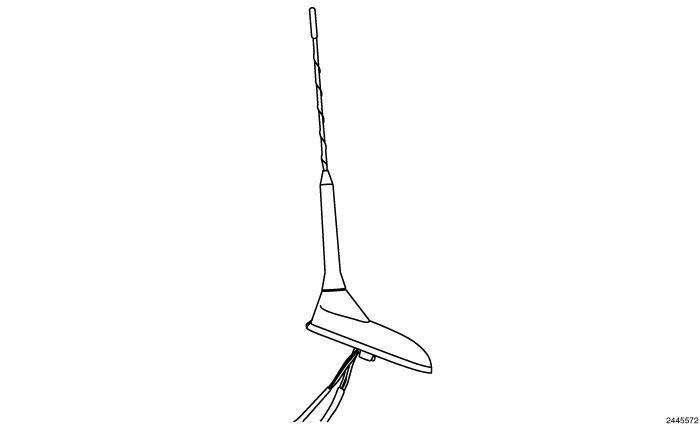
If the vehicle is equipped with satellite audio, a combined antenna for AM/FM and satellite and navigation is used. For AM/FM only, the antenna looks similar and is mounting in the same location. For more information, refer to ANTENNA, SATELLITE, REMOVAL .
For information on how to use (special tool #9977-6, Kit, Radio Antenna Diagnostic) refer to the DTC DIAGNOSIS AND TESTING or Non DTCs DIAGNOSIS AND TESTING .
ANTENNA, SATELLITE > REMOVAL > REMOVAL
CAUTION:
Do not stand on the tire or the bumper while servicing the antenna. Failure to follow the instructions will cause pers onal injury and/or vehicle damage.
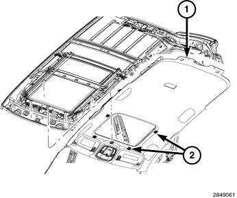
Courtesy of CHRYSLER GROUP, LLC
Disconnect and isolate the battery negative cable. 1.
Lower the rear portion of the rear headliner (1) as necessary to access underside of antenna. Refer to HEADLINER, REMOVAL . 2.
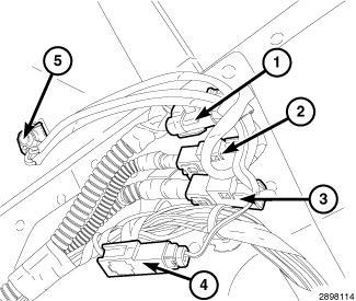
Courtesy of CHRYSLER GROUP, LLC
3.
Disconnect the navigation (1), SDAR (2), AM/FM (3) and the 5 volt power (4) wire harness connectors from the antenna.
4.
5.
Remove the antenna mounting retainer (5).
From inside the vehicle, and using a flat bladed tool, depress one of the retaining tabs on the antenna. Push up the one side of the antenna connector through the roof panel. Depress the other side of the connector and remove the antenna.
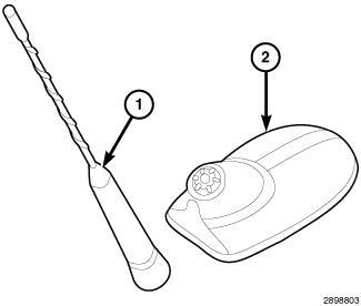
Courtesy of CHRYSLER GROUP, LLC
Remove the antenna mast (1) from the antenna base (2). 6.
ANTENNA, SATELLITE > INSTALLATION > INSTALLATION
CAUTION:
Do not stand on the tire or the bumper while servicing the antenna. Failure to follow the instructions will cause pers onal injury and/or vehicle damage.
CLICK HERE TO DOWNLOAD THE COMPLETE MANUAL
• Thank you very much for reading the preview of the manual.
• You can download the complete manual from: www.heydownloads.com by clicking the link below
• Please note: If there is no response to CLICKING the link, please download this PDF first and then click on it.
CLICK HERE TO DOWNLOAD THE
Courtesy of CHRYSLER GROUP, LLC
Install the antenna mast (1) to the antenna base (2). 1.
Insert wire harness through hole in roof panel. Press antenna into position until both retainers snap into place. 2.
Courtesy of CHRYSLER GROUP, LLC
3. Install the retaining fastener.
Connect the navigation (1), SDAR (2), AM/FM (3) and the 5 volt power (4) wire harness connectors to the antenna.
4.
Tighten to 6 N.m (53 In. Lbs.)
5. Connect the battery negative cable.
Install the headliner (1). Refer to HEADLINER, INSTALLATION .
6.
CABLE, ANTENNA, INSTRUMENT PANEL > REMOVAL > REMOVAL
WARNING:
Disable the airbag system before attempting any steering wheel, steering column, seat belt tensioner, side airbag or instrument panel component diagnosis or service. Disconnect and isolate the negative battery (ground) cable. Wait two minutes for the airbag system capacitor to discharge before performing further diagnosis or service. This is the only sure way to disable the airbag system. Failure to follow thes e instructions may result in accidental airbag deployment and possible serious or fatal injury.
1: Removing/Installing Radio Connectors
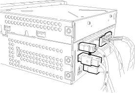
Courtesy of CHRYSLER GROUP, LLC
1. Remove radio. Refer to RADIO, REMOVAL .
Disconnect and isolate the battery negative cable.
2.
CAUTION:
Pulling the antenna cable straight out of the radio without pulling on the locking antenna connector could damage the cable or radio.
3. Remove the glove box.
Disconnect the antenna cable by pulling the locking antenna connector (2) away from the radio (1).
4.
5.
Remove instrument panel side panel.
Disconnect instrument panel cable (1) from antenna body and cable (2). 6.
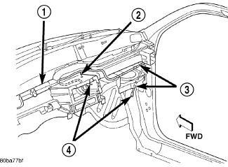
Courtesy of CHRYSLER GROUP, LLC
Remove the antenna retaining straps and remove antenna cable (4). 7.
CABLE, ANTENNA, INSTRUMENT PANEL > REMOVAL > REMOVAL > EXPORT
WARNING:
Disable the airbag system before attempting any steering wheel, steering column, seat belt tensioner, side airbag or instrument panel component diagnosis or service. Disconnect and isolate the negative battery (ground) cable. Wait two minutes for the airbag system capacitor to discharge before performing further diagnosis or service. This is the only sure way to disable the airbag system. Failure to follow thes e instructions may result in accidental airbag deployment and possible serious or fatal injury.
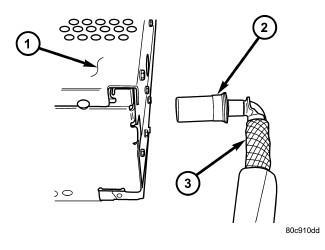
Disconnect and isolate the battery negative cable. 1.
2.
Remove the instrument panel. Refer to PANEL, INSTRUMENT, REMOVAL .
CAUTION:
Pulling the antenna cable straight out of the radio without pulling on the locking antenna connector could damage the cable or radio.
3.
Disconnect the antenna cable by pulling the locking antenna connector (2) away from the radio (1).
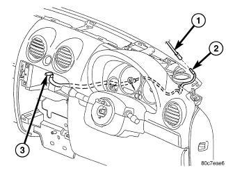
Disengage each of the retainers that secure the cable (2) to the instrument panel and remove cable. 4.
CABLE, ANTENNA, INSTRUMENT PANEL > INSTALLATION > INSTALLATION > DOMESTIC
of CHRYSLER GROUP, LLC
Install cable (3) to instrument panel and secure into place. 1.
Connect instrument panel cable (1) to antenna body and cable (2). 2.
Install instrument panel side panel. 3.
Install glove box. 4.
Courtesy of CHRYSLER GROUP, LLC
5. Install radio. Refer to RADIO, INSTALLATION .
Connect instrument panel cable (3) to radio (1).
6.
Connect battery negative cable.
7. CABLE, ANTENNA, INSTRUMENT PANEL > INSTALLATION > INSTALLATION > EXPORT
CLICK HERE TO DOWNLOAD THE COMPLETE MANUAL
• Thank you very much for reading the preview of the manual.
• You can download the complete manual from: www.heydownloads.com by clicking the link below
• Please note: If there is no response to CLICKING the link, please download this PDF first and then click on it.
CLICK HERE TO DOWNLOAD THE
Install instrument panel cable (2) to instrument panel and secure into place. 1.
Courtesy of CHRYSLER GROUP, LLC
Connect instrument panel cable (3) to radio. 2.
Install the instrument panel. Refer to PANEL, INSTRUMENT, INSTALLATION . 3.
Connect the battery negative cable. 4.
CAMERA, REAR > DESCRIPTION > DESCRIPTION
The Rear View Camera (RVC) (4) (also known as ParkView™), is a camera on chip device utilizing Complementary Metal Oxide Semiconductor (CMOS) technology. CMOS technology is used for a wide variety of digital or analog circuits. In this application, it supports the analog image sensor of the RVC. The RVC function is to provide a wide angle video image of the area behind the vehicle, including areas that might not be normally visible from the seated position of the vehicle operator, only while the transaxle gear selector is in the Reverse position or the camera delay is enabled and the gear selector goes from Reverse to Neutral or Drive. This video image then displays to the vehicle operator within the display screen of the audio system receiver unit near the center of the instrument panel. The image includes guideline overlay to aid operator the perception of distance. The active guidelines change direction with the steering wheel position to indicate the path of the vehicle to aid in parking. The guideline pattern also includes a center line to assist in trailer alignment.
The RVC is intended to be an auxiliary viewing aid and is not promoted as an obstacle detection or
safety device. It does not remove vehicle operator responsibility to recognize and obey official traffic laws or regulations or to take sensible precautions and care to avoid pedestrians, other vehicle traffic or both fixed and moving obstacles through the habitual use of safe and defensive driving techniques.
The RVC is mounted to the light bar assembly. The camera lens is visible on the vehicle center line, while the body of the camera and the camera connections are concealed within the liftgate. A wire harness routes into the interior of the liftgate where it connects the RVC to the vehicle electrical system.
Hardwired circuitry connects the RVC to the electrical system of the vehicle. These hardwired circuits are integral to several wire harnesses, which routes throughout the vehicle and retained by many different methods. These circuits may be connected to each other and to the vehicle electrical system through the use of a combination of soldered splices, splice block connectors, and many different types of wire harness terminal connectors and insulators. Refer to the appropriate wiring information. The wiring information includes wiring diagrams, proper wire and connector repair procedures, further details on wire harness routing and retention, as well as pin-out and location views for the various wire harness connectors, splices and grounds.
The RVC cannot be adjusted or repaired. If the RVC is damaged or ineffective, it must be replaced.
CAMERA, REAR > OPERATION > OPERATION
The Rear View Camera receives power from a run relay control output circuit located in the Power Distribution Center (PDC). The imager built into the rear view camera is active when the transmission is shifted into the Reverse position or with the camera delay feature on. When the transmission is shifted into the reverse position, the BCM sends a signal over the LIN bus to the rear view camera that excites the imager internal to the camera. The camera will then use hard wired video signal output circuits to provide the radio video display unit with compatible National Television System Committee (NTSC)
standard composite video M format data, or NTSC-M. These camera output circuits run through the entire length of the vehicle and are arranged in tandem as a twisted pair. Portions of these video signal wires are contained within the body wire harness and a jumper harness located between the radio and the body harness connector below the instrument panel located at the right cowl side inner panel. Data signal protection from corruption and interference is provided by a grounded foil jacket shield which is terminated only at the video display (radio).
CAMERA, REAR > DIAGNOSIS AND TESTING > DIAGNOSIS AND TESTING - REAR CAMERA
The hardwired circuits of the Rear View Camera (RVC) and those between the RVC and the Radio may be diagnosed using conventional diagnostic tools and procedures. Refer to the appropriate wiring information. The wiring information includes wiring diagrams, proper wire and connector repair procedures, details of wire harness routing and retention, connector pin-out information and location views for the various wire harness connectors, splices and grounds.
However, conventional diagnostic methods will not prove conclusive in the diagnosis of the RVC or the radio. The most reliable, efficient and accurate means to diagnose the electronic controls and communication related to radio operation, as well as the retrieval or erasure of a DTC requires the use of a diagnostic scan tool. Refer to the appropriate diagnostic information.
WARNING:
To avoid serious or fatal injury on vehicl es equipped with airbags, disable the Supplemental Restraint System (SRS) before attempting any steering wheel, steering column, airbag, seat belt tensioner, impact sensor, or instrument panel component diagnosis or service. Disconnect and isolate the battery negative (ground) cable, then wait two minutes for the system capacitor to discharge before performing further diagnosis or service. This is the only sure way to disable the SRS. Failure to take the proper precautions could result in accidental airbag deployment.
NOTE:
Be certain to confirm the following prior to attempting any further diagnosis or testing of the RVC. Use a diagnostic scan tool to confirm the rear view camera is setup in the vehicle configuration.
NOTE:
Before proceeding with the diagnostic steps below, use the scan tool to check the Body Control Module (BCM) for any camera or LIN bus related Diagnostic Trouble Codes (DTC). Repair as necessary.
VIDEO IMAGE IS BLURRY OR OBSTRUCTIVE
1. Dirt, smear, fingerprints on RVC lens.
1. Inspect lens for foreign material, and clean lens as required, using the lens cleaning procedure.
NO VIDEO DISPLAY IN RADIODOES NOT DISPLAY CHECK ENTIRE SURROUNDINGS
MESSAGE BRIEFLY AFTER SHIFTING INTO REVERSE
2. Ineffective camera shield circuit.
NO CAMERA IMAGE IN RADIO
VIDEO DISPLAY - DOES DISPLAY CHECK ENTIRE SURROUNDINGS MESSAGE BRIEFLY AFTER SHIFTING INTO REVERSE AND BACKUP LAMPS DO OPERATE
3. Moisture buildup on the inside of the lens.
2. Check for loose or damaged wiring connections at the camera, light bar, upper liftgate opening header, right cowl side inner panel and radio. Test and repair the open or shorted camera shield circuit if required.
3. Replace the ineffective camera as required.
1. Incorrect radio software.
2. Ineffective radio fuse.
3. Ineffective radio ground circuit.
1. Check to be certain that the radio has the latest software update installed. Install the radio software update if required.
2. Test and replace the radio fuses if required.
3. Check for loose or damaged wiring connections at the radio. Test and repair the open radio ground circuit if required.
4. Ineffective radio feed circuit.
5. Ineffective radio inputs or outputs.
4. Check for loose or damaged wiring connections at the radio. Test and repair the open radio feed circuit if required.
5. Use a diagnostic scan tool to test the radio inputs and outputs including those received over the CAN bus. Refer to the appropriate diagnostic information.
6. Ineffective radio.
1. Ineffective camera ground circuit.
6. Use a diagnostic scan tool to test the radio. Refer to the appropriate diagnostic information.
1. Check for loose or damaged wiring connections at the camera, light bar and liftgate. Test and repair the open camera ground circuit if required.
2. Ineffective camera feed (Run relay) circuit.
2. Check for loose or damaged wiring connections at the camera,
NO GRIDLINES BEING OVERLAID ON IMAGE
3. Ineffective camera return circuit.
light bar and upper liftgate opening header. Test and repair the open camera feed (Run relay) circuit if required.
3. Check for loose or damaged wiring connections at the camera, light bar, upper liftgate opening header, right cowl side inner panel and radio. Test and repair the open or shorted camera feed circuit if required.
4. Ineffective camera signal circuit.
5. Ineffective camera.
1. Setting is not checked in the radio settings screen.
2. Message be received is incorrect.
3. LIN connection is broken.
Disconnect and isolate the negative battery cable.
4. Check for loose or damaged wiring connections at the camera, light bar, upper liftgate opening header, right cowl side inner panel and radio. Test and repair the open or shorted camera signal circuit if required.
5. Replace the ineffective camera if required.
1. Adjust setting in radio settings screen.
2. Use a diagnostic scan tool to check for DTC's within other modules. Refer to appropriate diagnostic information for that DTC.
3. Refer to wiring diagrams and repair wiring as necessary.
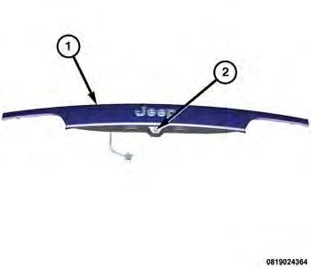
Courtesy of CHRYSLER GROUP, LLC
2.
Remove the lamp bar (1) to gain access to the rear camera (2). Refer to LAMP BAR, EXTERIOR HANDLE, REMOVAL .
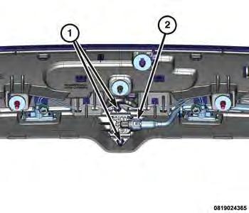
Courtesy of CHRYSLER GROUP, LLC
3.
Disconnect the electrical harness connector (2).
Remove the two rear camera mounting fasteners (1). 4.
Remove the rear camera from the lamp bar. 5.
CAMERA, REAR > INSTALLATION > INSTALLATION
Install the rear camera to the lamp bar. 1.
Install the two rear camera mounting fasteners (1). 2.
3.
Connect the electrical harness connector (2).
CLICK HERE TO DOWNLOAD THE COMPLETE MANUAL
• Thank you very much for reading the preview of the manual.
• You can download the complete manual from: www.heydownloads.com by clicking the link below
• Please note: If there is no response to CLICKING the link, please download this PDF first and then click on it.
CLICK HERE TO DOWNLOAD THE
Courtesy of CHRYSLER GROUP, LLC
Install the lamp bar (1). Refer to LAMP BAR, EXTERIOR HANDLE, INSTALLATION . 4. Connect the negative battery cable. 5.
COMPONENTS, RADIO NOISE SUPPRESSION > DESCRIPTION > DESCRIPTION
Radio noise suppression devices are installed on this vehicle. Radio Frequency Interference (RFI) and ElectroMagnetic Interference (EMI) can be produced by any on-board or external source of electromagnetic energy. These electromagnetic energy sources can radiate electromagnetic signals through the air, or conduct them through the vehicle electrical system.
When the audio system converts RFI or EMI to an audible acoustic wave form, it is referred to as radio noise. This undesirable radio noise is generally manifested in the form of "buzzing," "hissing," "popping," "clicking," "crackling," and/or "whirring" sounds. In most cases, RFI and EMI radio noise can be suppressed using a combination of vehicle and component grounding, filtering and shielding techniques. This vehicle is equipped with radio noise suppression devices that were designed to minimize exposure to typical sources of RFI and EMI; thereby, minimizing radio noise complaints.
Radio noise suppression is accomplished primarily through circuitry or devices that are integral to the radios, audio power amplifiers and other on-board electrical components such as generators, wiper motors, blower motors, and fuel pumps that have been found to be potential sources of RFI or EMI. External radio noise suppression devices that are used on this vehicle to control RFI or EMI, and can be serviced, include the following:
Engine-to-bulkhead ground strap - This length of braided ground strap has an eyelet terminal connector crimped to each end. One end is secured to the engine cylinder heads. The other is secured to the bulkhead.
Resistor-type spark plugs - This type of spark plug has an internal resistor connected in series between the spark plug terminal and the center electrode to help reduce the production of electromagnetic radiation that can result in radio noise.
Exhaust-to-frame ground strap - This length of braided ground strap has an eyelet terminal connector crimped to each end. One end is secured to the exhaust pipe. The other is secured to the frame.
COMPONENTS, RADIO NOISE SUPPRESSION > OPERATION > OPERATION
There are two common strategies that can be used to suppress Radio Frequency Interference (RFI) and ElectroMagnetic Interference (EMI) radio noise. The first suppression strategy involves preventing the production of RFI and EMI electromagnetic signals at their sources. The second suppression strategy involves preventing the reception of RFI and EMI electromagnetic signals by the audio system components.
The use of braided ground straps in key locations is part of the RFI and EMI prevention strategy. These ground straps ensure adequate ground paths, particularly for high current components such as many of those found in the starting, charging, ignition, engine control and transmission control systems. An insufficient ground path for any of these high current components may result in radio noise caused by induced voltages created as the high current seeks alternative ground paths through components or circuits intended for use by, or in close proximity to the audio system components or circuits.
Preventing the reception of RFI and EMI is accomplished by ensuring that the audio system components are correctly installed in the vehicle. Loose, corroded or improperly soldered wire harness connections, improperly routed wiring and inadequate audio system component grounding can all contribute to the reception of RFI and EMI. A properly grounded antenna body and radio chassis, as well as a shielded antenna coaxial cable with clean and tight connections will each help reduce the potential for reception of RFI and EMI.
COMPONENTS, RADIO NOISE SUPPRESSION > REMOVAL > ENGINE TO BODY
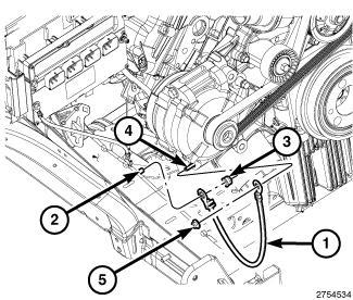
Courtesy of CHRYSLER GROUP, LLC
Remove the lower front generator mounting retainer (5). 1.
2.
3.
Remove the retainer (3) from the body ground stud (2).
Remove the ground strap (1) from the lower front generator mounting stud (4) and the body ground stud (2).
COMPONENTS, RADIO NOISE SUPPRESSION > REMOVAL > EXHAUST TO BODY
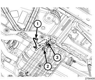
Courtesy of CHRYSLER GROUP, LLC
Raise the hoist. 1.
2.
Unclip the ground strap (1) from the exhaust body hanger (3) to the exhaust hanger (2) on the catalytic converter.
COMPONENTS, RADIO NOISE SUPPRESSION > REMOVAL > HOOD TO BODY
CLICK HERE TO DOWNLOAD THE COMPLETE MANUAL
• Thank you very much for reading the preview of the manual.
• You can download the complete manual from: www.heydownloads.com by clicking the link below
• Please note: If there is no response to CLICKING the link, please download this PDF first and then click on it.
CLICK HERE TO DOWNLOAD THE
Fig 1: Two Retainers, Fender Stud & Ground Strap
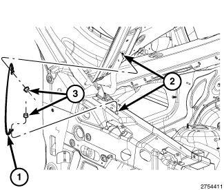
Courtesy of CHRYSLER GROUP, LLC
2.
Open the hood. 1. Remove the two retainers (3) from the hood and fender stud (2) and remove the ground strap (1).
COMPONENTS, RADIO NOISE SUPPRESSION > REMOVAL > PCM TO BODY TO ENGINE
NOTE:
The ground strap is V shaped and attaches to three different locations.
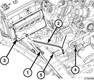
Courtesy of CHRYSLER GROUP, LLC
1.
Remove the retainer (1) attaching the ground strap (2) to the PCM (3).
2.
Remove the retainer (4) attaching the ground strap (2) to the body ground stud (5).
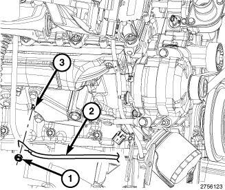
3.
Remove the retainer (1) attaching the ground strap (2) to the engine stud (3).
COMPONENTS, RADIO NOISE SUPPRESSION > INSTALLATION > ENGINE TO BODY
1. Install the retainer (3) onto the body ground stud (2).
Install the ground strap (1) on the body stud (2) and to the front lower generator stud (4).
2. Install the retainer (5) to the front lower generator stud (4).
Tighten to 23 N.m (17 Ft. Lbs).
3. COMPONENTS,
Tighten to 23 N.m (17 Ft. Lbs).
CLICK HERE TO DOWNLOAD THE COMPLETE MANUAL
• Thank you very much for reading the preview of the manual.
• You can download the complete manual from: www.heydownloads.com by clicking the link below
• Please note: If there is no response to CLICKING the link, please download this PDF first and then click on it.
CLICK HERE TO DOWNLOAD THE