UNITSOFMEASURE
ThismanualadoptstheunitsofmeasurebasedonInternationalSystem. TheMKSAsystemunitsofmeasureareindicatedwithinbracketsaftertheunitsofmeasureoftheInternational System.
Example:24.5MPa(250kgf/cm2)
ThefollowingtableconvertstheInternationalSystemunitsofmeasureinsomeofthemainunitsbelongingtoother system.
QuantityToconvert from(IS) Into (Others)MultiplybyQuantityToconvert from(IS) Into (Others)Multiplyby
Lenght mmin0.03937 PressureMPakgf/cm210.197 mmft0.003281MPapsi145.0
Volume LUSgal0.2642PowerkWCV-PS1.360 LUSqt1.057kWHP1.341 m3yd31.308Temperature°C°F°Cx1.8+32 Masskglb2.205Speedkm/hmph0.6214
ForceNkgf0.10197 min-1rpm1.0 Nlbf0.2248
CapacityL/minUSgpm0.2642
TorqueN.mkgf.m0.10197mL/revcc/rev1.0 N.mlbf.ft0.7375
GeneralInformation Contents
GeneralInformation.......................0A-2
ServicePrecautions......................0A-2
Readingthemodel.......................0A-6
Generalinformation......................0A-7
ServicePrecautions
Inordertocarryoutworksafely
1.Alwaysuseanenginestandwhentakingthe enginedownfromthevehicle. Donotplacetheenginedirectlyontotheground, orplaceinamannerthatinterfereswiththeoil pan.
2.Ifyouareworkingtogetherwithothers,alwayspay attentiontoeachother'ssafety.
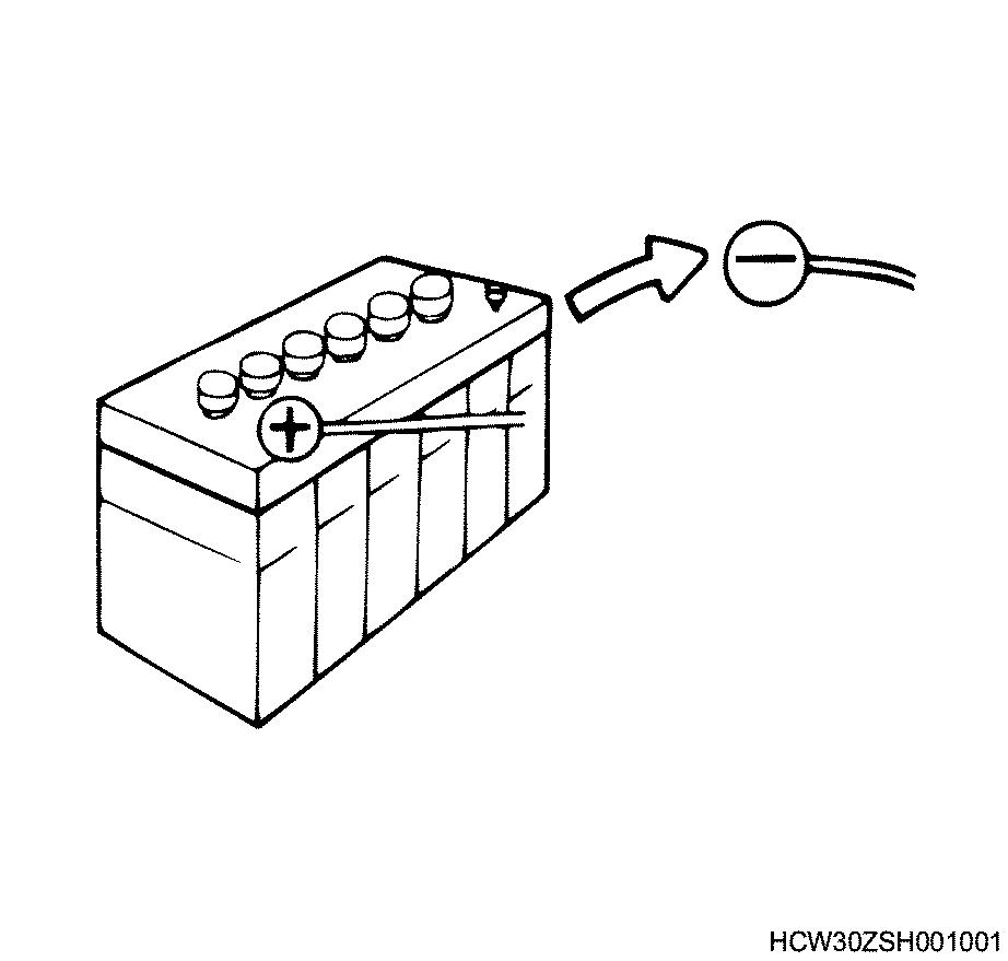
3.Ifyouarerepairinganypartoftheelectrical system,alwaysremovetheminussidecablefrom thebatteryterminalbeforestartingwork.Ifyouare removingthebatterycover,alwaysremovethe coverinaplacethatisawayfromsourcesoffire/ heat.
4.Donotperformpaintingworkorleavetheengine runningforlongperiodsoftimeinanenclosedor badlyventilatedindoorworkshop.
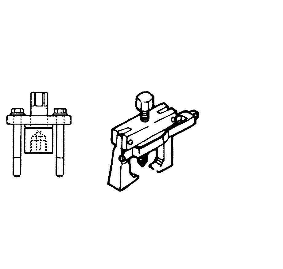
5.Alwaysusethecorrectspecializedtoolindicatedin theinstructions.Usingtheincorrecttoolmay causedamagetothepartsorinjurytotheperson usingthetool.
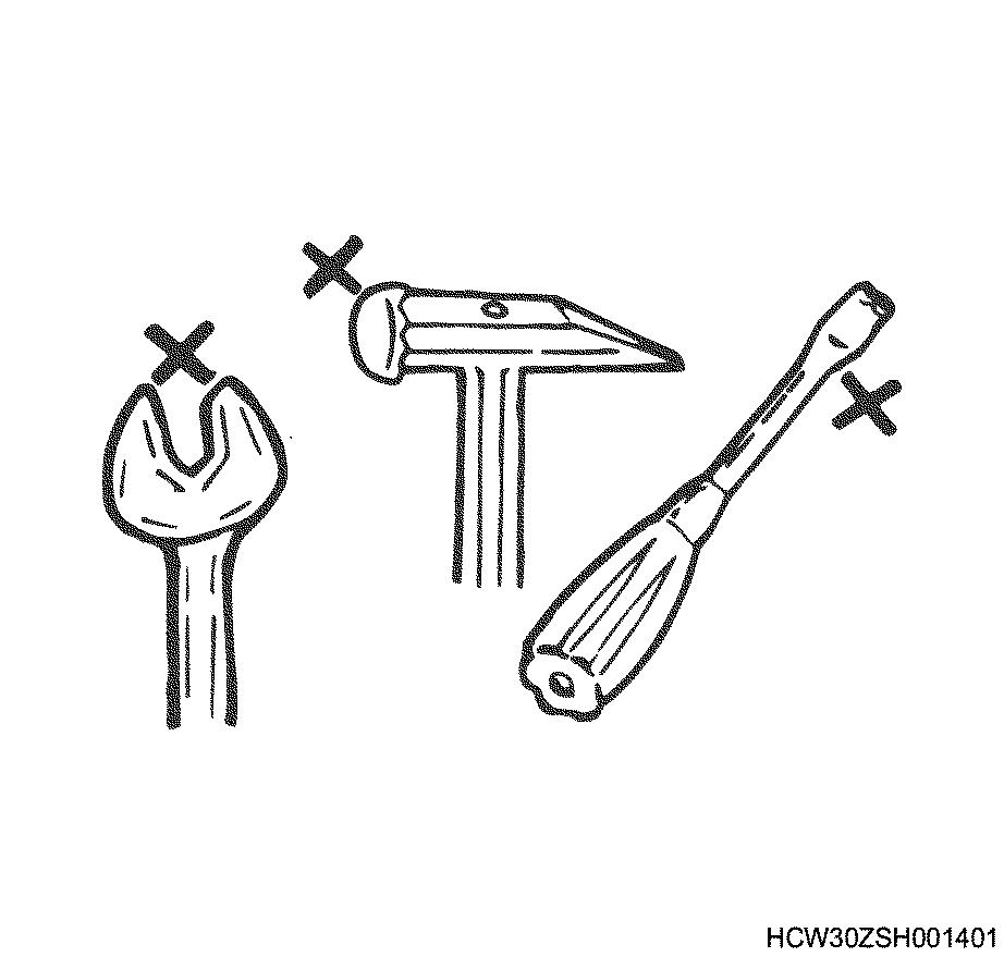
6.Allregulartools,gaugesandspecialtoolsshould beregularlyinspected,andpreparedbefore startingwork.Donotusebentspanners,hammers withdamagededges,chippedchisels,oranyother faultyordamagedtools.
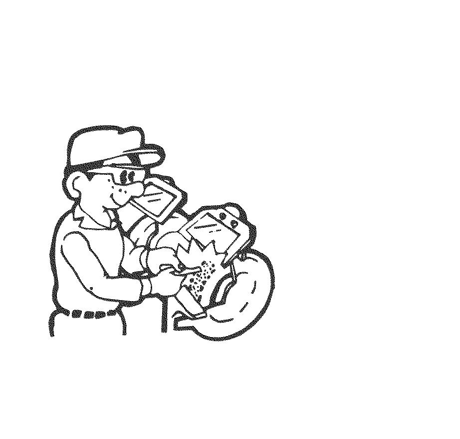
7.Alwayspaycloseattentiontosafetyandhandling requirementswhenusinggrinders,cranes, welders,andothersuchequipment. Moreover,alwayswearthecorrectprotective garmentsandusethenecessarysafetytoolsfor thejobinhand.
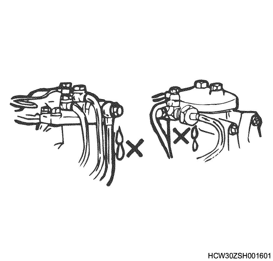
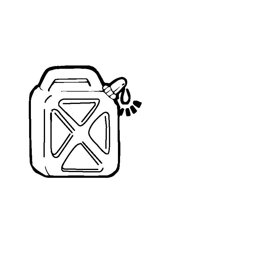
8.Alwayscheckthattherearenofuelleakswhen performingmaintenanceworkonthefuelsystem. (Itmaycauseafire.)
9.Paycloseattentiontotheriskofignitionifyouare handlingpartsthatcarryahighvoltage. Furthermore,anyoilorfatspiltontorubberparts mustbewipedoffimmediately,asitwillcause deteriorationoftherubber.
Replacementpartsandpartnumbers.
1.Alwaysreplacepacking,oilseals,o-rings,caulking locknuts,foldinglockplates,splitpinsandother suchpartswithbrandnewparts.
2.Thepartsnumberscontainedinthismanualmay notrepresentthesupplyconditionoftheparts,and thepartnumbersmaybechangeddueto revisions.Therefore,partsshouldalwaysbe checkedagainstapartscataloguebeforeuse.
Liquidgasket
1.Eachtimeyoudisassemblepartsthatuseliquid gasket,completelyremovetheoldgasketresidue fromeachofthepartsandmatchingsectionsusing ascraper,thencleaneachofthepartsto completelyremoveoil,water,anddirtetc.fromthe varioussurfaces.Usingthespecifiedtypeofliquid gasket,applynewliquidgaskettoeachofthe surfacesbeforereassemblingtheparts.
2.Inordertomakeiteasiertocleanliquidgasket surfaces,applygasketremoverliquid(Pando391DmadebyThreeBondCo.,Ltd.)andleave theparttostandforapproximately10minutes, afterwhichtheoldliquidgasketresiduewillbe easiertoremove.
However,thisshouldnotbeusedonresin componentsorpaintedcomponents.
3.Pleasetakecarenottoapplytoomuchortoolittle liquidgasket.
Also,youshouldalwaysre-applytheliquidgasket uponitselfwhenyoustartandfinishapplication.
4.Makesurethattherearenogapswhenreinstallingtheliquidgasketpartstoeachother.If therearegapsbetweenthetwoparts,re-applythe liquidgasket.Someparts,especiallytheoilpan, usethesamesizestudsasaguidetoeliminatethe needforknockpinpositioningetc.
5.Re-installthesepartswithin7minutesofapplying theliquidgasket.
0A-4GeneralInformation
Ifmorethan7minutespasses,removethe previousliquidgasketandre-applyit.
6.Pleasewaitforatleast30minutessincethelast partisinstalledbeforestartingtheengine.
Liquidgasket
SealsectionProductnameManufacturer'sname
BetweencylinderblockandFlywheelhousing1207BThreeBond BetweencylinderblockandFlywheelhousingand Crankcase 1207BThreeBond
BetweencylinderblockandCrankcase1207BThreeBond BetweencylinderblockandFrontcover1207BThreeBond Cylinderblock,headplugnipple,unit,switches262Loctite
Alwaysusetheliquidgasketproductslistedabove, oraliquidgasketidenticaltotheoneslistedabove.
Usethecorrectquantityofliquidgasket.Always followthehandlinginstructionsforeachproduct.
Applicationprocedure
1.Wipethecontactsurfacescleanofallwater,fator oil.Thecontactsurfacesshouldbedry.
2.Applyaregularbeadwidthofliquidgaskettoone ofthecontactsurfaces.Makesurethatthebead doesnotbreakatthispoint.
Notes:
Iftherearespecialregulationsconcerningthe applicationprocedureintherepairdocument,please followthoseregulations.
Workprocedure
1.Wipethejointsurfacesofthebolt,bolthole,and screwthreadsectioncleanofwater,fat,andoil. Thecontactsurfacesshouldbedry.
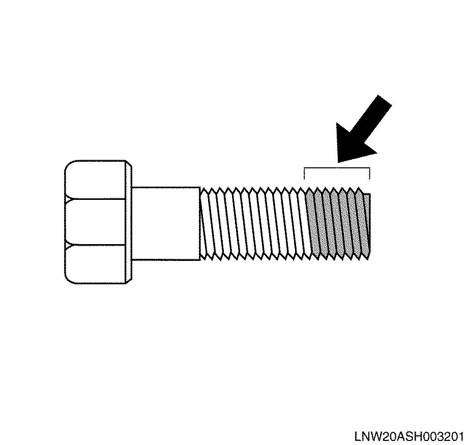
2.ApplyLoctitetothetop1/3ofthescrew.
3.Tightenthebolttothecorrecttighteningtorque.
Important:
Aftertighteningthebolt,donotapplyexcessivetorque ortrytorotatetheboltuntilatleastonehourhas passed,andtheLoctitehashardened.
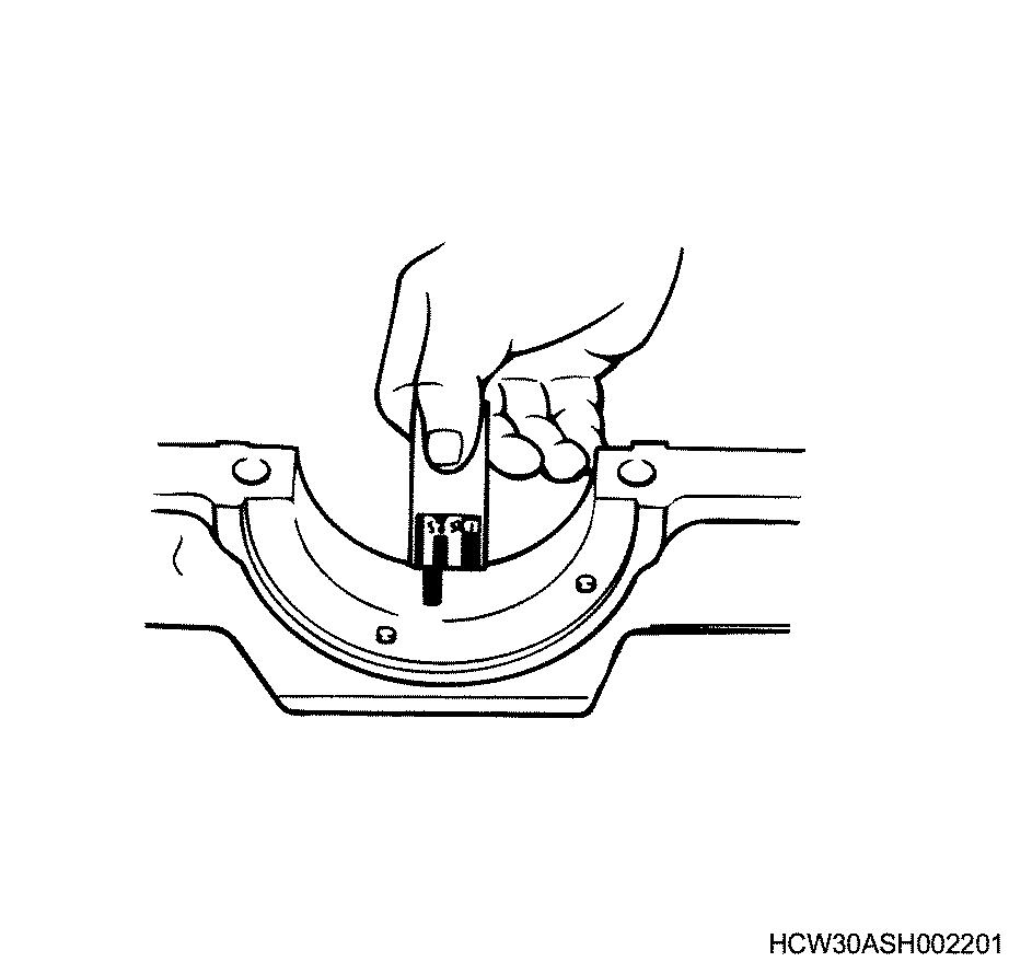
ProcedureforusingthePlastiguage
TypeMeasurablerangemm(in)
PG-1(Green)0.0250.076(0.0010.003)
PR-1(Red)0.0510.152(0.0020.006)
PB-1(Blue)0.1020.229(0.0040.009)
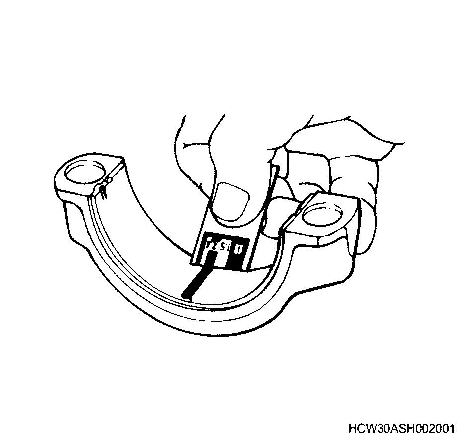
Example:Procedureformeasuringtheclearance betweentheconnectingrodbearingandcrankpin.
Cleantheconnectingrodandbearing,andinstall thebearingtotherod.
Cuttheplastiguagetothesamewidthasthecrank pin,andwhileavoidingtheoilporeofthecrankpin laythegaugeparalleltothepin.
Lineupthemarksontheconnectingrodandcap andinstallthecrankpin,applymolybdenum disulphidetothethreadsectionandbearing surfaceofthefasteningbolt,androtatebothcap andbolttothecorrecttorque.
Important:
Donotmovetheconnectingrodwhileusingthe plastiguage.
Gentlyremovethecapandconnectingrod,and measurethecrushedwidthoftheplastiguage (clearancebetweenrodandpin)usingthescale printedonthebag.
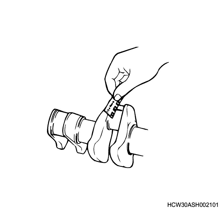
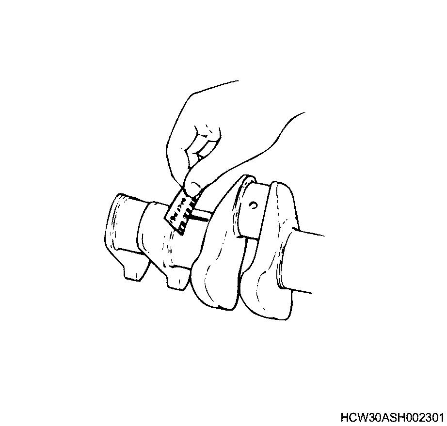
Example:Measuringtheclearancebetweenthecrank bearingandcrankjournal
Cleantheclampfaceofthecylinderblockand crankcasebearing,andalsothebearing,and installthecylinderblocktothecrankcase.
Gentlyrestthecrankshaftonthecylinderblock, androtateitapproximately30degreetostabilizeit.
Cuttheplastiguagetothesamesizeasthejournal width,andwhileavoidingtheoilporeofthejournal laythegaugeparalleltothejournal.
Gentlyrestthecrankcaseonthecylinderblock, applymolybdenumdisulphidetothethreadsection andbearingsurfaceofthefasteningbolt,and tighteninsequencetothecorrecttorque.
Important:
Donotrotatethecrankshaftwhileusingthe plastiguage.
Gentlyremovethecrankcase,andmeasurethe crushedwidthoftheplastiguage(clearance betweenbearingandjournal)usingthescale printedonthebag.
Readingthemodel
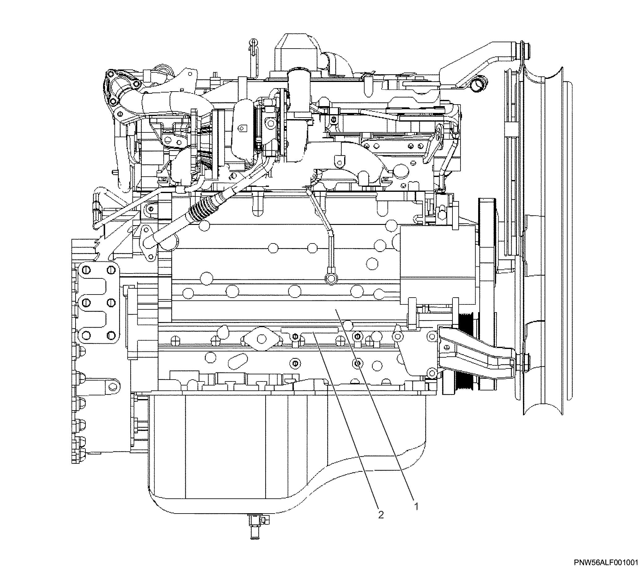
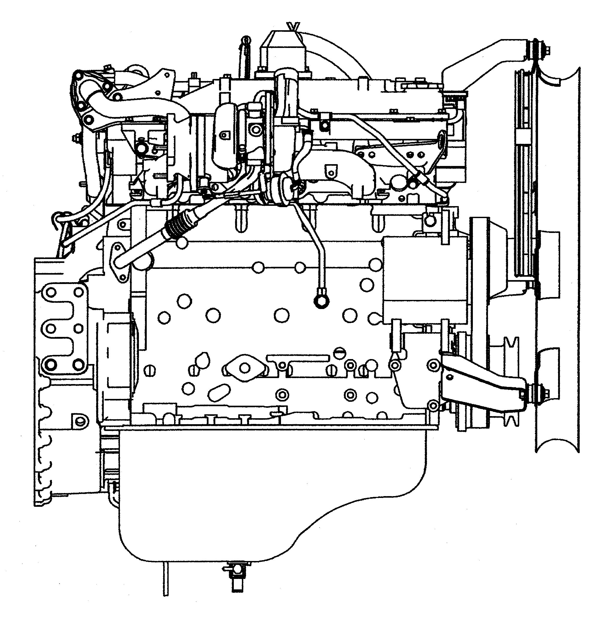
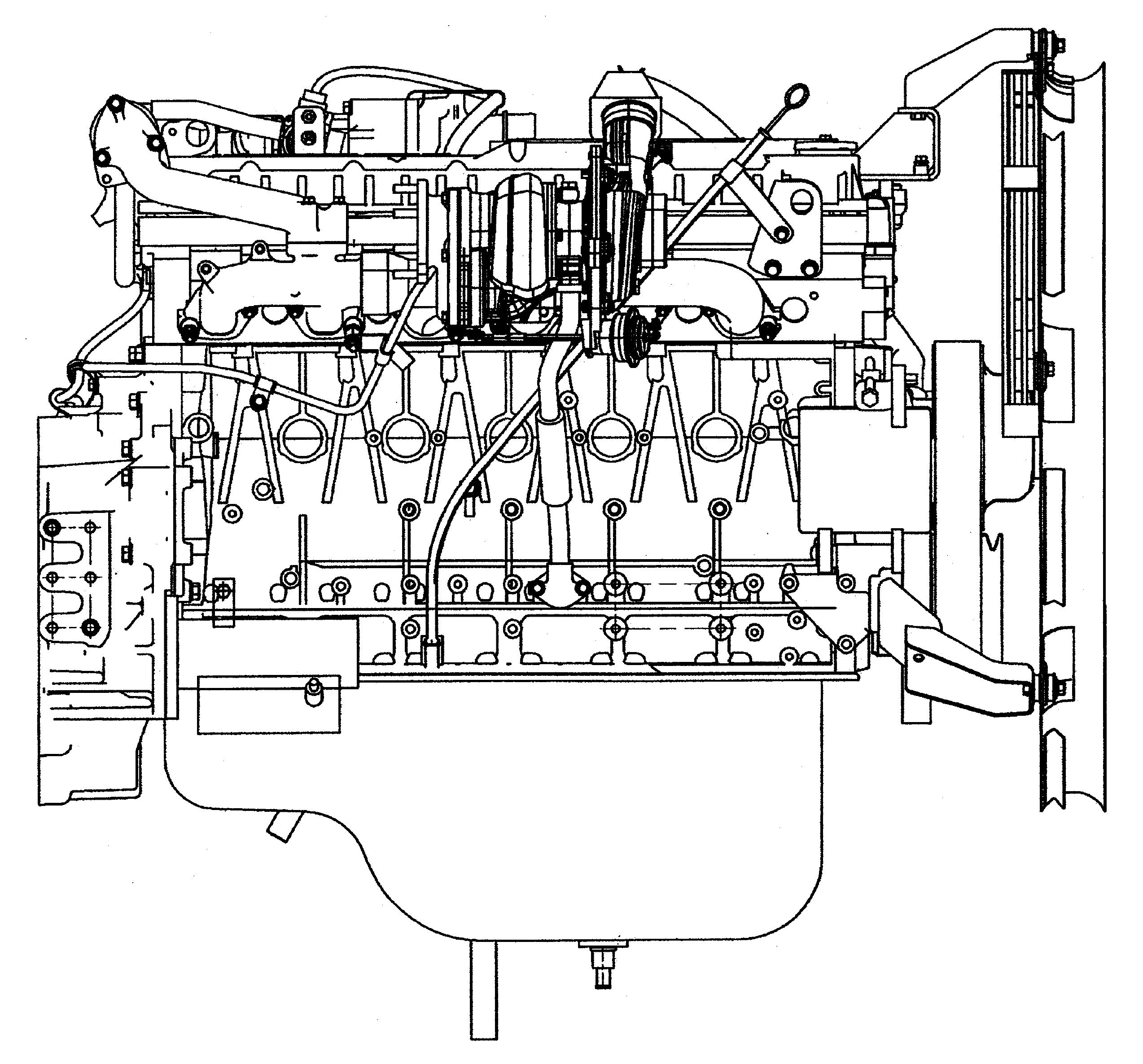
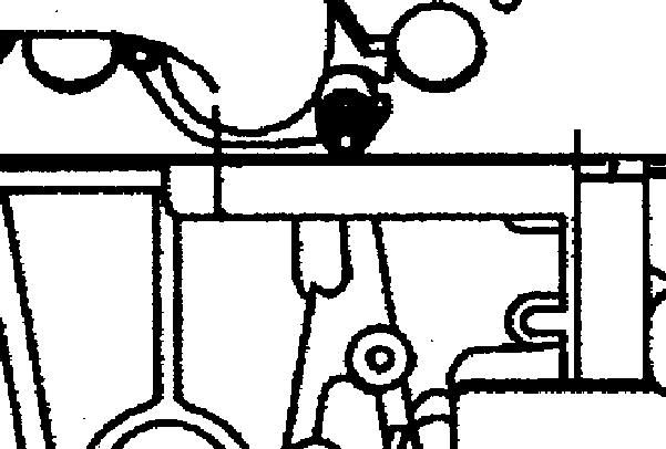
Enginenumberstampingposition
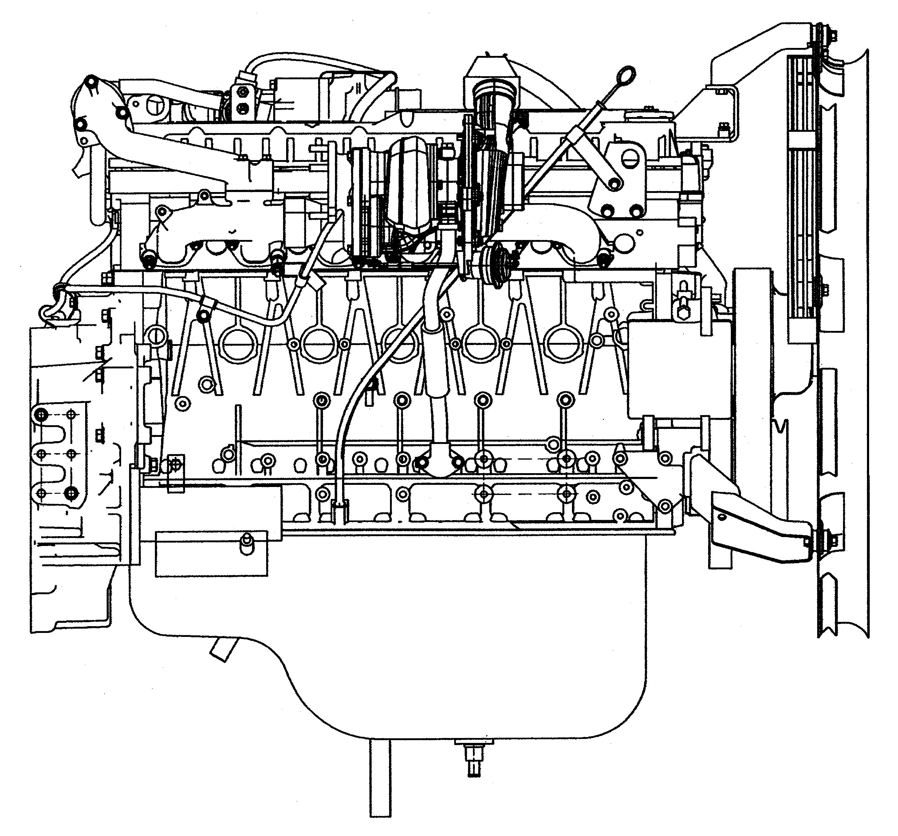
4HK1
Generalinformation
Terminology,descriptionofabbreviations
Terminologydefinitions
TermExplanation
MaintenancestandardThegenericnameforreferencevaluesrequiredformaintenance,suchasnominal dimension,selectionofareferencepoint,andlimit.
NominaldimensionShowsthestandardvalueatthepointofmanufacturethatdoesnotincludethe commondifference.
SelectionofareferencepointShowsthestandardvalueafterassembling,repairing,oradjusting.
LimitWhenthisvalue(dimensions)isreached,itshowsthattheparthasreacheditsfull limitandmustbereplacedorrepaired.
Frontrear,leftright,upper lower Theseshoweachorientationsofpartsinstalledtothevehiclewhenlookingfrom thevehicle'sforwarddirection.
UnitUnitswrittentoSIconventions(mainlytorque,pressure,force) [Example]Length:mm,Torque:Nm{kgfm}
WarningItemsthatcarrythewarningmarkposeadangertolifeorthreatofseriousinjuryif notstrictlyobserved.
CautionItemsthatcarrythecautionmarkmaycauseinjuryorleadtoaccidentsifnotstrictly observed.
ImportantItemsthatcarrytheimportantmarkmaycausethevehicletobreakdown,ormay preventtheguaranteednormaloperationofthesystemorrelatedpartsifnotstrictly observed.
0A-8GeneralInformation
TermExplanation
NotesItemsthatshouldreceivespecialmentionwithinaworkprocedure.
Descriptionofabbreviations
AbbreviationDescription
ACAlternatingCurrent AlternatingCurrent
ACCAccessory Accessory
ACGAlternatingCurrentGenerator Alternatingcurrentgenerator
APIAmericanPetrolInstitute AmericanPetroleumInstitute
ASM(Assy)Assembly Assembly
ATDCAfterTopDeadCenter AfterTopDeadCenter
BAT,BATTBattery Battery
BRG,BrgBearing Bearing
BKT,BRKTBracket Bracket
BTDCBeforeTopDeadCenter BeforeTopDeadCenter
COCarbonOxide CarbonMonoxide
CONNConnector Connector
CPUCentralProcessingUnit Centralprocessingunit
C/UControlUnit Controlunit
DCDirectCurrent Directcurrent
DIDirectInjection Directinjection
ECUEngineControlUnit/ElectronicControl Unit
Enginecontrolunit/controlunit
ECMEngineControlModule Enginecontrolmodule
EGRExhaustGasRecirculation
Exhaustgasrecirculation
Exh,EXHExhaust Exhaust
Ft,FRTFront Front
AbbreviationDescription
FWDForward Forward
F/CFuelCut FuelCut
GNDGround Earth
ICIntegratedCircuit Integratedcircuit
IDPlateIdentificationplate Identificationplate,IDplate
INIntake,Intake Intake
ISOInternationalOrganizationfor Standardization InternationalOrganizationfor Standardization
I/PUMPInjectionPump InjectionPump
JISJapaneseIndustrialStandard JapaneseIndustrialStandard
L/H,LHLeftHand Lefthandside
M/VMagneticValve Magneticvalve
NOxNitrogenOxide NitrogenOxide
N-TDCNumber-TopDeadCenter Topdeadcenterrotationalfrequency
OPTOption Option
PPole(S) Pole
PCVPumpControlValve/Positive CrankcaseVentilation Pumpcontrolvalve/Positivecrankcase ventilation
PMParticulateMatter Particulatematter
PSPre-Stroke Pre-stroke
PTOPowerTakeOff Powertakeoff
QOSQuickOnSystem Rapidpreheatingsystem
Rr,RRRear
Rear
AbbreviationDescription
R/H,RHRightHand Righthandside
R/LRelay
Relay
STDStandard Standard
SWSwitch Switch
TICSTiming&InjectionrateControlSystem
Atypeofinjectionsystem
VGSTurboVariableGeometryturbocharger System
Adjustableturbo,VGSturbo
W/LWarningLamp Warninglamp
SI(InternationalSystemofUnits)
WithregardstheconversiontoSI(International SystemofUnits)
TheintroductionoftheSIsystemsaimsto internationallyunifythemetricsystemandthevarious unitsusedbydifferentcountries(traditionalweights andmeasures,thefootpoundmethodetc.),andto curbtheconfusionthatoccursbetweenthedifferent units(conversioncalculationsetc.).
ThenewcalculatingmethodwhichadoptedSIunits wascompletelyadoptedinJapanin1992,andis standardizedbyJIS-Z-8203.
Alloftheunitsinthismanualarewritteninlinewiththe InternationalSystemofUnitsSIunits,andconventional unitsarewrittenin{}brackets.
SI
French)AbbreviatednameofLeSystemeInternational dUnites
ConnectionbetweenmainSIunitsandconventionalunits
SIConventionalUnitItem,unitconversion
LengthmmSameastheconventionalunit
Weight(Mass)kgkgSameastheconventionalunit
ForceN*kg,kgf1kgf=9.80665N
TorqueNm*kgm,gfm1kgfm=9.80665Nm
PressurePa*kg/cm2,mmHg1kgf/cm2=9.80665kPa,1mmHg=133.3Pa
Dynamicforce,horsepowerWPS1PS=0.74kW
Capacity,airvolumedisplacementm3Litle,L,cc1Litle=1dm3,1cc=1mLitle=1cm3
Fuelconsumptiong/(kWh)g/(PSh)1g/(PSh)=1.360g/(kWh)
*1Publishedservicedatamayconvenientlyusekgfor forceandmass(weight)insteadofkgf.
*2Someconversionresultsmayberoundedoffto1or 2decimalplaces.
Convertingexpressionsofquantity
Whenconverting,prefixessuchask(kilo)orm(mili) areused.
200kgf/cm2=19,620kPa=19.6MPa
40mmHg=5,332Pa=5.3kPa
TableofstandardIsuzutighteningtorque
Thetighteningtorquevaluesinthetablebelowapplyto allsituationsunlessaspecialtighteningtorqueis specified.
Isuzustandardbolts,nuts
Bolthead sectionshapeHexagonheadboltFlangeboltHexagonheadboltFlangebolt
*M101.519.6~33.3{2.0~3.4}22.3~37.2{2.3~3.8}27.5~45.1{2.8~4.6}30.3~50.4{3.1~5.1}
M121.2549.0~73.5{5.0~7.5}54.9~82.3{5.6~8.4}60.8~91.2{6.2~9.3}68.1~102.1{6.9~ 10.4}
*M121.7545.1~68.6{4.6~7.0}51.0~76.5{5.2~7.8}56.9~84.3{5.8~8.6}62.7~94.0{6.4~9.6} M141.576.5~114.7{7.8~ 11.7} 83.0~124.5{8.5~ 12.7}
*M14271.6~106.9{7.3~ 10.9} 77.2~115.8{7.9~ 11.8} 88.3~131.4{9.0~ 13.4} 94.9~142.3{9.7~ 14.5}
M161.5104.0~157.0{10.6~ 16.0} 115.6~173.3{11.8~ 17.7}
23.0}
*M162100.0~149.1{10.2~ 15.2} 109.4~164.2{11.2~ 16.7} 129.4~194.2{13.2~ 19.8} 142.5~213.8{14.5~ 21.8}
M181.5151.0~225.6{15.4~ 23.0}
*M182.5151.0~225.6{15.4~ 23.0}
M201.5206.0310.0{21.0~ 31.6}
*M202.5190.2~286.4{19.4 29.2}
M221.5251.1413.8{25.6~ 42.2}
*M222.5217.7~327.5{22.2~ 33.4}
M242358.9~539.4{36.6~ 55.0}
*M243338.3~507.0{34.5~ 51.7}
195.2~293.2{19.9~ 29.9}
196.1~294.2{20.0~ 30.0}
269.7~405.0{27.5~ 41.3}
249.1~374.6{25.4~ 38.2}
362.8~544.3{37.0~ 55.5}
338.3~507.0{34.5~ 51.7}
430.5~711.0{43.9~ 72.5}
406.0~608.0{41.4~ 62.0}
The*markindicateswheresoftmaterialshavebeenusedforinternalthreadsections,suchascastings.
Strengthclassification8.8
The*markindicateswheresoftmaterialshavebeenusedforinternalthreadsections,suchascastings. Nm{kgfm}
M61 5.6~11.2{0.6~ 1.1} 6.6~12.2{0.6~ 1.2}
M81.2513.4~25.7{1.4~ 2.6}
2.9}
3.1}
3.4} M101.2531.3~52.5{3.2~ 5.4}
*M121.7564.8~96.1{6.6~ 9.8} 71.4~107.2{7.3~ 10.9}
12.2} M141.5106.2~158.8{10.8 ~16.2} 114.9~172.3{11.7 ~17.6}
*M142100.6~149.8{10.3 ~15.3} 108.2~162.2{11.1 ~16.6}
M161.5154.3~232.5{15.7 ~23.7} 171.1~256.7{17.4 ~26.2}
*M162147.6~221.4{15.0 ~22.6} 162.5~243.8{16.6 ~24.9}
M181.5222.5~334.3{22.7 ~34.1}
*M182.5223.6~335.4{22.8 ~34.2}
M201.5307.4~461.7{31.4 ~47.1}
*M202.5284.0~472.1{29.0 ~43.5}
M221.5413.6~620.5{42.2 ~63.3}
*M222.5385.7~578.0{39.3 ~58.9}
M242490.8~810.5{50.0 ~82.7}
*M243462.8~693.1{47.2 ~70.7}
~17.4}
~16.3}
~24.5}
~18.9}
~17.7}
~27.1}
~23.4} 168.5~252.7{17.2 ~25.8}
229.5~345.2{23.4 ~35.2}
230.5~346.2{23.6 ~35.3}
316.8~475.6{32.3 ~48.5}
293.2~440.3{29.2 ~44.9}
424.6~636.5{43.3 ~64.9}
394.2~592.3{40.0 ~60.4}
554.1~830.6{56.5 ~84.7}
520.7~781.6{53.1 ~79.7}
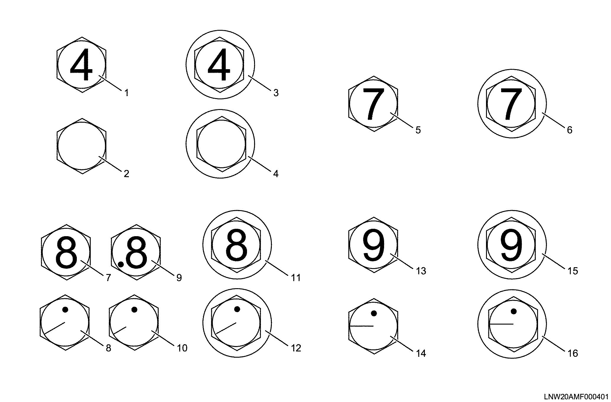
DesignationsforIsuzustandardboltheads
Legend
1.Hexagonheadbolt(4.8,4T)
2.Hexagonheadbolt(4.8,4T)
3.Flangebolt(4.8,4T)
4.Flangebolt(4.8,4T)
5.Hexagonheadbolt(7T)
6.Flangebolt(7T)
7.Hexagonheadbolt(refined8.8)
8.Hexagonheadbolt(refined8.8)
Flarenut
9.Hexagonheadbolt(Un-refined8.8)
10.Hexagonheadbolt(Un-refined8.8)
11.Flangebolt(8.8)
12.Flangebolt(8.8)
13.Hexagonheadbolt(9.8,9T)
14.Hexagonheadbolt(9.8,9T)
15.Flangebolt(9.8,9T)
16.Flangebolt(9.8,9T)
Pipediametertighteningtorque (formediumandlarge sizevehicles)
Flarenut2sidewidth(mm)
Flarenuttighteningtorque(service standardvalue)Nm{kgfm} 4.76mm12.8~18.6{1.3~1.9}1414 6.35mm23.5~49{2.4~5.0}1717 8.0mm23.5~49{2.4~5.0}1917 10.0mm44.1~93.2{4.5~9.5}2219 12.0mm58.8~137.3{6.0~14.0}2724 15.0mm78.5~156.9{8.0~16.0}3030
Taperscrewfromconnectors(brass) Nm{kgfm}
ScrewsizePT(R)1/8PT(R)1/4PT(R)3/8PT(R)1/12
2.0~14.7 (0.2~1.5)
(0.5~1.6)