

PC300LL-7E0
LOGGING/ROADBUILDER EXCAVATOR
ThismaterialisproprietarytoKomatsuAmericaCorp.andisnottobereproduced,used,ordisclosedexceptinaccordance withwrittenauthorizationfromKomatsuAmericaCorp..
Itisourpolicytoimproveourproductswheneveritispossibleandpracticaltodoso.Wereservetherighttomakechangesor addimprovementsatanytimewithoutincurringanyobligationtoinstallsuchchangesonproductssoldpreviously.
Duetothiscontinuousprogramofresearchanddevelopment,periodicrevisionsmaybemadetothispublication.Itis recommendedthatcustomerscontacttheirdistributorforinformationonthelatestrevision.
MEMORANDUM
10STRUCTURE,FUNCTIONANDMAINTENANCESTANDARD
20TESTING,ADJUSTINGANDTROUBLESHOOTING.
30DISASSEMBLYANDASSEMBLY.
90OTHER.
SAFETYNOTICE
IMPORTANTSAFETYNOTICE
Properserviceandrepairisextremelyimportantforthesafeoperationofyourmachine.Theserviceandrepairtechniques recommendedanddescribedinthismanualarebotheffectiveandsafemethodsofoperation.Someoftheseoperations requiretheuseoftoolsspeciallydesignedforthepurpose.


Topreventinjurytoworkers,thesymbolsandareusedtomarksafetyprecautionsinthismanual.Thecautions accompanyingthesesymbolsshouldalwaysbefollowedcarefully.Ifanydangeroussituationarisesormaypossiblyarise, firstconsidersafety,andtakethenecessaryactionstodealwiththesituation.
GENERALPRECAUTIONS
00
Mistakesinoperationareextremelydangerous.ReadtheOPERATION&MAINTENANCEMANUALcarefullyBEFORE operatingthemachine.
1.Beforecarryingoutanygreasingorrepairs,readalltheprecautionsgivenonthedecalswhicharefixedtothemachine.
2.Whencarryingoutanyoperation,alwayswearsafetyshoesandhelmet.Donotwearlooseworkclothes,orclotheswith buttonsmissing.
•Alwayswearsafetyglasseswhenhittingpartswithahammer.
•Alwayswearsafetyglasseswhengrindingpartswithagrinder,etc.
3.Ifweldingrepairsareneeded,alwayshaveatrained,experiencedweldercarryoutthework.Whencarryingoutwelding work,alwayswearweldinggloves,apron,glasses,capandotherclothessuitedforweldingwork.
4.Whencarryingoutanyoperationwithtwoormoreworkers,alwaysagreeontheoperatingprocedurebeforestarting. Alwaysinformyourfellowworkersbeforestartinganystepoftheoperation.Beforestartingwork,hangUNDER REPAIRsignsonthecontrolsintheoperator'scompartment.
5.Keepalltoolsingoodconditionandlearnthecorrectwaytousethem.
6.Decideaplaceintherepairworkshoptokeeptoolsandremovedparts.Alwayskeepthetoolsandpartsintheircorrect places.Alwayskeeptheworkareacleanandmakesurethatthereisnodirtoroilonthefloor.Smokeonlyintheareas providedforsmoking.Neversmokewhileworking.
PREPARATIONSFORWORK
1.Beforeaddingoilormakingrepairs,parkthemachineonhard,levelground,andblockthewheelsortrackstopreventthe machinefrommoving.
2.Beforestartingwork,lowerblade,ripper,bucketoranyotherworkequipmenttotheground.Ifthisisnotpossible,insert thesafetypinoruseblockstopreventtheworkequipmentfromfalling.Inaddition,besuretolockallthecontrollevers andhangwarningsignsonthem.
3.Whendisassemblingorassembling,supportthemachinewithblocks,jacksorstandsbeforestartingwork.
4.Removeallmudandoilfromthestepsorotherplacesusedtogetonandoffthemachine.Alwaysusethehandrails,laddersorstepswhengettingonoroffthemachine.Neverjumponoroffthemachine.Ifitisimpossibletousethehandrails, laddersorsteps,useastandtoprovidesafefooting.
PRECAUTIONSDURINGWORK
1.Whenremovingtheoilfillercap,drainplugorhydraulicpressuremeasuringplugs,loosenthemslowlytopreventtheoil fromspurtingout.Beforedisconnectingorremovingcomponentsoftheoil,wateroraircircuits,firstremovethepressure completelyfromthecircuit.
2.Thewaterandoilinthecircuitsarehotwhentheengineisstopped,sobecarefulnottogetburned.Waitfortheoiland watertocoolbeforecarryingoutanyworkontheoilorwatercircuits.
3.Beforestartingwork,removetheleadsfromthebattery.ALWAYSremovetheleadfromthenegative(-)terminalfirst.
4.Whenraisingheavycomponents,useahoistorcrane.Checkthatthewirerope,chainsandhooksarefreefromdamage. Alwaysuseliftingequipmentwhichhasamplecapacity.Installtheliftingequipmentatthecorrectplaces.Useahoistor craneandoperateslowlytopreventthecomponentfromhittinganyotherpart.Donotworkwithanypartstillraisedby thehoistorcrane.
5.Whenremovingcoverswhichareunderinternalpressureorunderpressurefromaspring,alwaysleavetwoboltsinpositiononoppositesides.Slowlyreleasethepressure,thenslowlyloosentheboltstoremove.
6.Whenremovingcomponents,becarefulnottobreakordamagethewiring.Damagedwiringmaycauseelectricalfires.
7.Whenremovingpiping,stopthefueloroilfromspillingout.Ifanyfueloroildripsontothefloor,wipeitupimmediately. Fueloroilonthefloorcancauseyoutoslip,orcanevenstartfires.
8.Neveruseflammableliquidstocleanparts.Useonlynon-flammableapprovedcleaningsolutionstocleanparts.
9.Besuretoassembleallpartsagainintheiroriginalplaces.Replaceanydamagedpartwithnewparts.
•Wheninstallinghosesandwires,besurethattheywillnotbedamagedbycontactwithotherpartswhenthemachine isbeingoperated.
10.Wheninstallinghighpressurehoses,makesurethattheyarenottwisted.Damagedtubesaredangerous,sobeextremely carefulwheninstallingtubesforhighpressurecircuits.Alsocheckthatconnectingpartsarecorrectlyinstalled.
11.Whenassemblingorinstallingparts,alwaysusethespecifiedtighteningtorques.Wheninstallingprotectivepartssuchas guardsorpartswhichvibrateviolentlyorrotateathighspeed,beparticularlycarefultocheckthattheyareinstalledcorrectly.
12.Whenaligningtwoholes,neverinsertyourfingersorhand.Becarefulnottogetyourfingerscaughtinahole.
13.Whenmeasuringhydraulicpressure,checkthatthemeasuringtooliscorrectlyassembledbeforetakinganymeasurements.
14.Takecarewhenremovingorinstallingthetracksoftrack-typemachines.Whenremovingthetrack,thetrackseparates suddenly,soneverletanyonestandateitherendofthetrack.
00
Thisshopmanualhasbeenpreparedasanaidtoimprovethequalityofrepairsbygivingtheservicemananaccurateunderstandingoftheproductandbyshowinghimthecorrectwaytoperformrepairsandmakejudgements.Makesureyouunderstandthecontentsofthismanualanduseittofulleffectateveryopportunity.
Thisshopmanualmainlycontainsthenecessarytechnicalinformationforoperationsperformedinaserviceworkshop.For easeofunderstanding,themanualisdividedintothefollowingsections.Thesesectionsarefurtherdividedintoeachmain groupofcomponents.
GENERAL
Thissectionliststhegeneralmachinedimensions,performancespecifications,componentweights,andfuel,coolantand lubricantspecificationcharts.
STRUCTUREANDFUNCTION
Thissectionexplainsthestructureandfunctionofeachcomponent.Itservesnotonlytogiveanunderstandingofthe structure,butalsoservesasreferencematerialfortroubleshooting.
TESTING,ADJUSTINGANDTROUBLESHOOTING
Thissectionexplainscheckstobemadebeforeandafterperformingrepairs,aswellasadjustmentstobemadeatcompletionofthechecksandrepairs.Troubleshootingchartscorrelating“Problems”to“Causes”arealsoincludedinthissection.
DISASSEMBLYANDASSEMBLY
Thissectionexplainstheordertobefollowedwhenremoving,installing,disassemblingorassemblingeachcomponent, aswellasprecautionstobetakenfortheseoperations.
MAINTENANCESTANDARD
Thissectiongivesthejudgementstandardswheninspectingdisassembledparts.
NOTICE
Thespecificationscontainedinthisshopmanualaresubjecttochangeatanytimeandwithoutanyadvancenotice.Contact yourdistributorforthelatestinformation.
Inthewiringdiagrams,variouscolorsandsymbolsareemployedtoindicatethethicknessofwires.Thiswirecodetablewill helpyouunderstandWIRINGDIAGRAMS.
Example:05WBindicatesacablehavinganominalnumber05andwhitecoatingwithblackstripe.
CLASSIFICATION
0.85110.320.882.412Starting,lighting,signaletc. 2260.322.093.120Lighting,signaletc. 5650.325.234.637Chargingandsignal 15840.4513.367.059Starting(Glowplug) 40850.8042.7311.4135Starting 601270.8063.8413.6178Starting 1002170.80109.117.6230Starting
12 HOWTOREADTHESHOPMANUAL
VOLUMES
Shopmanualsareissuedasaguidetocarryingoutrepairs.Theyaredividedasfollows:
Chassisvolume:Issuedforeverymachinemodel
Enginevolume:Issuedforeachengineseries
Electricalvolume:Eachissuedasonetocoverallmodels
Attachmentvolume:Eachissuedasonetocoverallmodels
Thesevariousvolumesaredesignedtoavoidduplicationofinformation.Thereforetodealwithallrepairsforanymodel,itis necessarythatchassis,engine,electricalandattachmentbeavailable.
DISTRIBUTIONANDUPDATING
Anyadditions,amendmentsorotherchangeswillbesenttoyourdistributors.Getthemostup-to-dateinformationbeforeyou startanywork.
FILINGMETHOD
1.Seethepagenumberonthebottomofthepage.Filethepagesincorrectorder. 2.Followingexamplesshowhowtoreadthepagenumber: Example: 10-3
Itemnumber(10.StructureandFunction)
Consecutivepagenumberforeachitem
3.Additionalpages:Additionalpagesareindicatedbyahyphen(-)andnumberedafterthepagenumber.Fileasinthe example. Example:
REVISEDEDITIONMARK
Whenamanualisrevised,aneditionmark(…)isrecordedonthebottomoutsidecornerofthepages.
REVISIONS
RevisedpagesareshownattheLISTOFREVISEDPAGESbetweenthetitlepageandSAFETYpage.
SYMBOLS
Sothattheshopmanualcanbeofamplepracticaluse,importantplacesforsafetyandqualityaremarkedwiththefollowing symbols.
SymbolItemRemarks

SafetySpecialsafetyprecautionsarenecessarywhenperformingthework.
Caution
Weight
Specialtechnicalprecautionsorotherprecautionsforpreservingstandardsare necessarywhenperformingthework.
Weightofpartsorsystems.Cautionnecessarywhenselectinghoistingwireor whenworkingpostureisimportant,etc.
TighteningtorquePlacesthatrequirespecialattentionfortighteningtorqueduringassembly.
CoatPlacestobecoatedwithadhesivesandlubricantsetc.
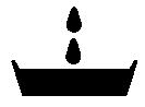
Oil,waterPlaceswhereoil,waterorfuelmustbeadded,andthecapacity.
DrainPlaceswhereoilorwatermustbedrained,andquantitytobedrained.
00
12 HOISTINGINSTRUCTIONS
HOISTING

WARNING!Heavyparts25kg(55lb)ormore)mustbeliftedwithahoistetc.IntheDISASSEMBLY ANDASSEMBLYsection,everypartweighing25kg(55lb)ormoreisindicatedclearly withthesymbol.
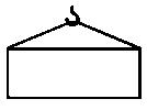
Ifapartcannotbesmoothlyremovedfromthemachinebyhoisting,thefollowingchecksshouldbemade:
1.Checkforremovalofallboltsfasteningtheparttotherelativeparts.
2.Checkforexistenceofanotherpartcausinginterfacewiththeparttoberemoved.
WIREROPES
1.Useadequateropesdependingontheweightofpartstobehoisted,referringtothetablebelow:
Wireropes (Standard“Z”or“S”twistropeswithoutgalvanizing)
11.2(0.44)13.71.4 12.5(0.49)15.71.6 14(0.55)21.62.2 16(0.63)27.52.8 18(0.71)35.33.6 20(0.79)43.14.4
Theallowableloadvalueisestimatedtobe1/6or1/7ofthebreakingstrengthoftheropeused.
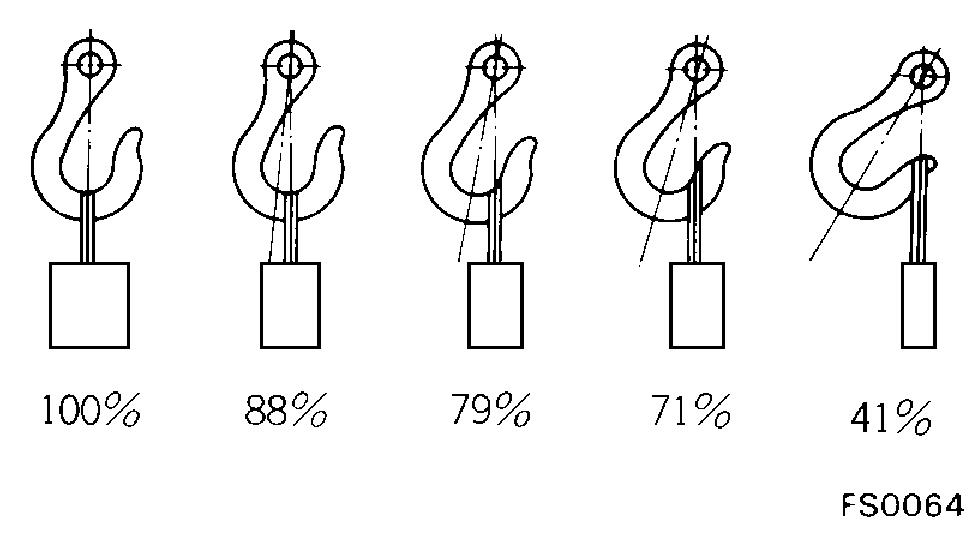
12 2.Slingwireropesfromthemiddleportionofthehook. Slingingneartheedgeofthehookmaycausetheropeto slipoffthehookduringhoisting,andaseriousaccident canresult.Hookshavemaximumstrengthatthemiddle portion.
3.Donotslingaheavyloadwithoneropealone,butsling withtwoormoreropessymmetricallywoundontothe load.

WARNING!Slingingwithoneropemay causeturningoftheloadduring hoisting,untwistingoftherope, orslippingoftheropefromits originalwindingpositiononthe load,whichcanresultinadangerousaccident.
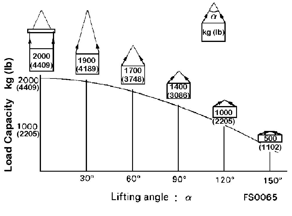
4.Donotslingaheavyloadwithropesformingawidehanginganglefromthehook.Whenhoistingaloadwithtwoor moreropes,theforcesubjectedtoeachropewillincrease withthehangingangles.Thetableshowsthevariationof allowableloadkg(lb)whenhoistingismadewithtwo ropes,eachofwhichisallowedtoslingupto1000kg (2205lb)vertically,atvarioushangingangles.Whentwo ropesslingaloadvertically,upto2000kg(4409lb)of totalweightcanbesuspended.Thisweightbecomes1000 kg(2205lb)whentworopesmakea120°hangingangle. Ontheotherhand,tworopesaresubjecttoanexcessive forceaslargeas4000kg(8818lb)iftheyslinga2000kg (4409lb)loadataliftingangleof150°.
12 PUSHPULLCOUPLER
WARNING!Beforecarryingoutthefollowingwork, releasetheresidualpressurefromthe hydraulictank.Fordetails,seeTESTING ANDADJUSTING,ReleaseRemaining PressureinHydraulicCircuit.
WARNING!Eveniftheresidualpressureisreleasedfrom thehydraulictank,somehydraulicoilflows outwhenthehoseisdisconnected. Accordingly,prepareanoilreceiving container.
TYPE1
DISCONNECTION
1.Releasetheresidualpressurefromthehydraulictank.Fordetails, seeTESTINGANDADJUSTING,ReleaseRemainingPressurein HydraulicCircuit.
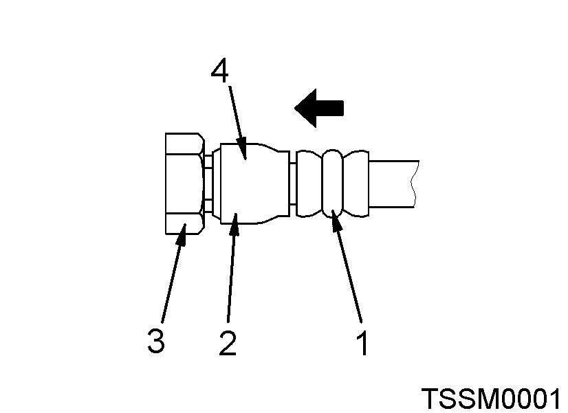
2.Holdtheadapter(1)andpushthehosejoint(2)intothemating adapter(3).Theadaptercanbepushedinabout3.5mm(0.14in). Donotholdtherubbercapportion(4).
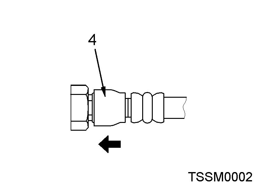
3.Afterthehosejoint(2)ispushedintotheadapter(3),pressthe rubbercapportion(4)againsttheadapteruntilitclicks.
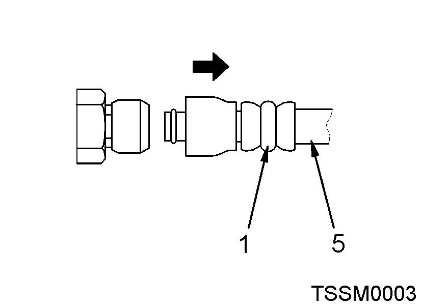
4.Holdthehoseadapter(1)orhose(5)andpullitout.Sincesome hydraulicoilflowsout,prepareanoilreceivingcontainer.
CONNECTION
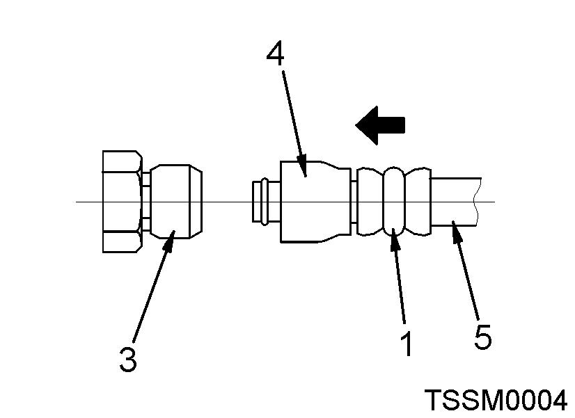
1.Holdthehoseadapter(1)orhose(5)andinsertitinthemating adapter(3),aligningthemwitheachother.Donotholdtherubber capportion(4).
2.Afterinsertingthehoseinthematingadapter,pullitbacktocheck itsconnectingcondition.Whenthehoseispulledback,therubber capportionmovestowardthehoseabout3.5mm(0.14in).This doesnotindicateanabnormality.
TYPE2
DISCONNECTION
1.Holdthemouthpieceofthetighteningportionandpushbody(2)in straightuntilslidingpreventionring(1)contactscontactsurfacea ofthehexagonalportionatthemaleend.
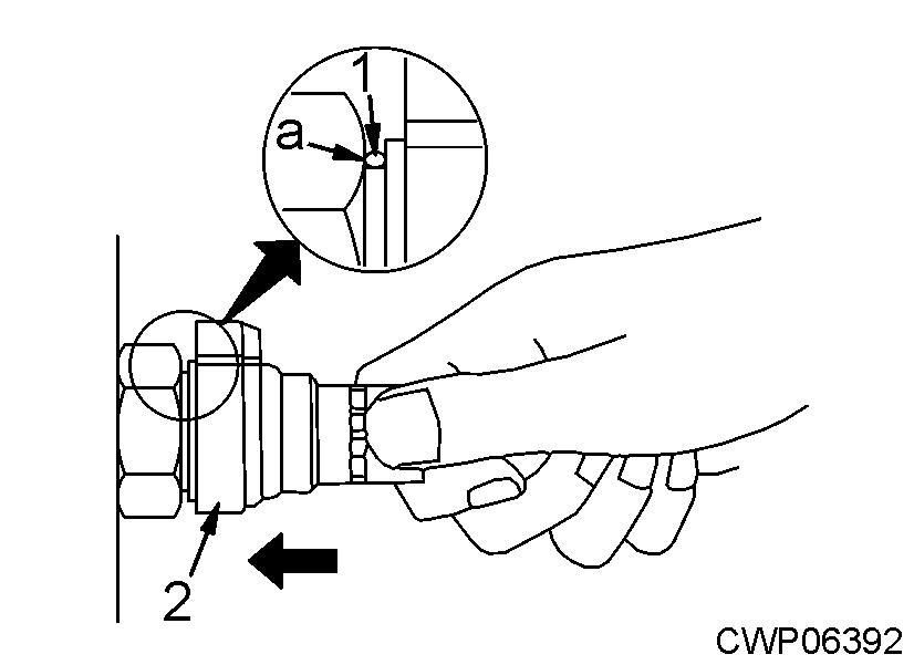
2.HoldintheconditioninStep1,andturnthelever(4)totherightclockwise.
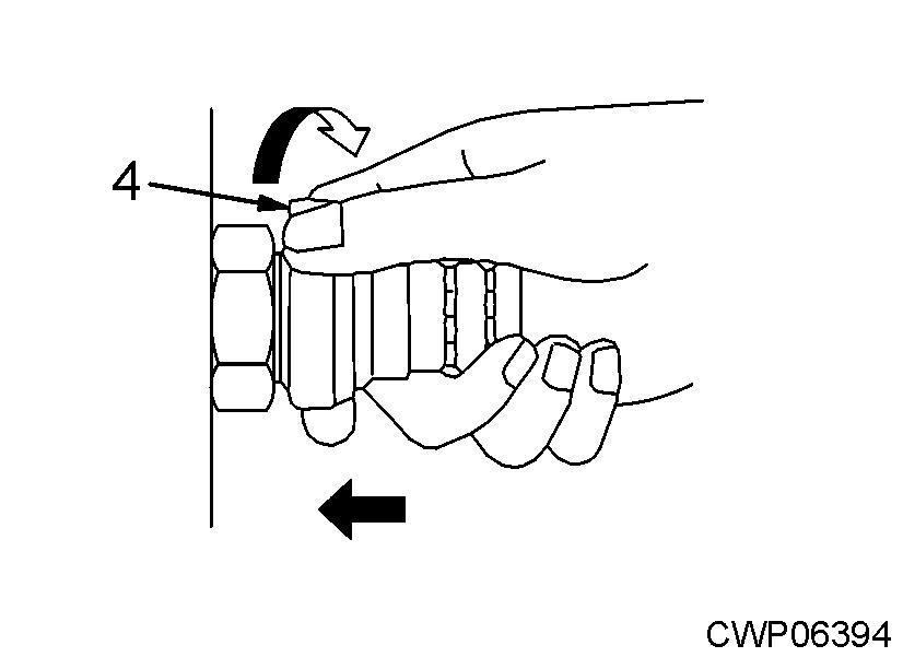
3.HoldintheconditioninSteps1and2,andpulloutthewholebody (2)todisconnectit.
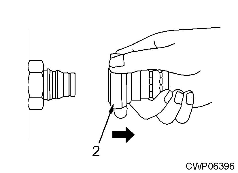
CONNECTION
1.Holdtheconnectorofthetighteningportionandpushbody(2)in straightuntilslidingpreventionring(1)contactssurface(a)ofthe hexagonalportionatthemaleendtoconnectit.
12 TYPE3
DISCONNECTION
1.Holdtheconnectorofthetighteningportionandpushthebody(2) instraightuntilslidingpreventionring(1)contactssurface(a)of thehexagonalportionatthemaleend.
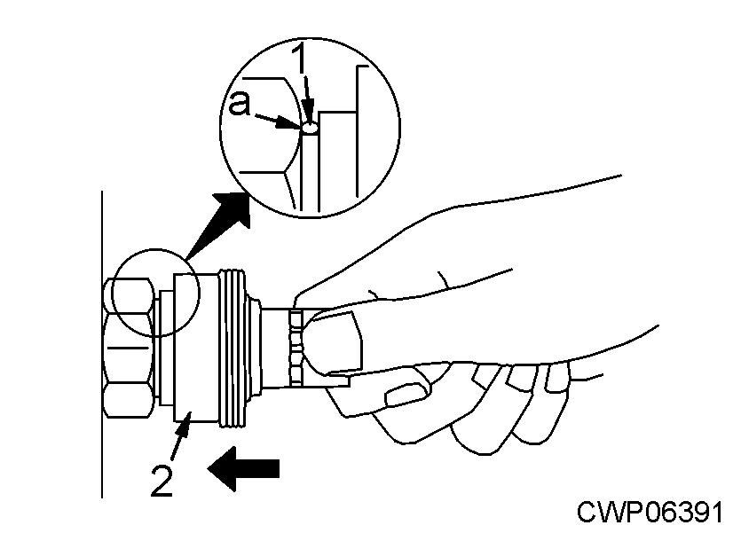
2.HoldintheconditioninStep1,andpushuntilthecover(3)contactssurface(a)ofthehexagonalportionatthemaleend.
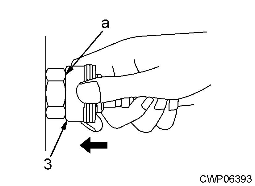
3.HoldintheconditioninSteps1and2,andpulloutthewholebody (2)todisconnectit.
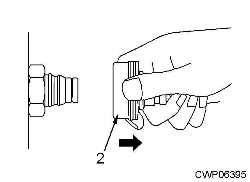
CONNECTION
1.Holdtheconnectorofthetighteningportionandpushthebody(2) instraightuntiltheslidepreventionring(1)contactssurface(a)of thehexagonalportionatthemaleendtoconnectit.