

SR4 GENERATOR


Product: GENERATOR
Model: SR4 GENERATOR 9AB
Configuration: GENERATOR MOUNTED CONTROL PANEL EMCP II 9AB00001-UP
Disassembly and Assembly
SR4 Generator with VR3 or VR4 Voltage Regulator
-SENR3985-02
Bearing - Remove and Install
SMCS - 4471-010
Removal Procedure
Start By:
A. Remove the exciter field and remove the exciter armature. Refer to Disassembly and Assembly, "Exciter - Remove and Install" and Disassembly and Assembly, "RotorRemove and Install".
Table 1
1H-3107 Push-Puller 1
1H-3108 Push-Puller Leg 2
1H-3110 Bearing Pulling Attachment 1
i01643729
Illustration 1
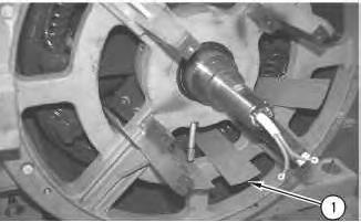
(1) Protective strip
1. Put protective strips (1) of cardboard, plastic or curved sheet metal between the rotor assembly and the stator assembly. The pieces should be as long as the rotor assembly. During removal of the end housing, these pieces protect the rotor and the stator from damage.
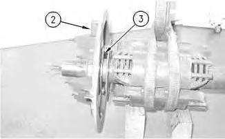
2. The generator bearing is retained in the generator end housing. On the inside of the generator end housing, a bearing cap or retaining bars are used to retain the bearing.
(2) Bolts
(3) Retaining Bars
3. If the generator end housing is equipped with retaining bars (3), remove the four bolts (2) that fasten the retaining bars to the generator end housing. Remove the retaining bars.
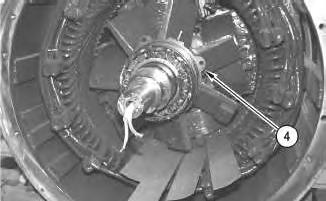
Illustration 2
g00854020
Illustration 3
g00854023
This is the sample of the manual click on the download link for complete manual
DOWNLOAD LINK
For some reason if link does not work download this pdf and then click
4. If the generator end housing is equipped with bearing cap (4), remove the necessary bolts which fasten the bearing cap to the generator end housing. Pry the bearing cap out of the generator end housing. The bearing cap remains with the rotor shaft. If a bearing lube line is attached to the bearing cap, remove the lube line.
4
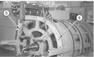
(5) End Housing (6) Bolts
Note: The weight of end housing (5) varies with the size of the generator. Larger end housings require the use of a hoist.
5. Attach a hoist to end housing (5). Remove bolts (6) that fasten end housing (5) to the generator. Use a pry bar to separate the end housing from the generator. Some end housings have provisions which allow the use of forcing screws. Lift the end housing from the generator and remove the end housing from the generator.
5 g00854021
Illustration
g00854025
Illustration
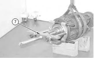
6. Attach tooling (7). Remove the bearing.
Two-Bearing Generator
Table 2
TOOLS NEEDED
Part Number Tool Quantity
1U-6415 Puller Group (40 ton) 1
Note: On two-bearing generators, there is a bearing on each end of the generator. To remove the bearing that is located at the drive end of the generator, use the following procedure.
For removal of the bearing at the drive end of the generator, begin by removing the drive coupling. Refer to Disassembly and Assembly, "Coupling - Remove".
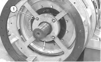
1. The generator bearing is retained in the generator end housing. On the inside of the generator end housing, a bearing cap retains the bearing.
Remove bolts (1) which fasten the bearing cap to the generator end housing. Pry the bearing cap out of the generator end housing. The bearing cap remains with the rotor shaft. If a bearing lube line is attached to the bearing cap, remove the lube line.
2. Put a mark on the drive end housing and the generator housing. This will ensure proper alignment during installation.
Illustration 6
g00615814 (1) Bolts
7
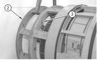
(2) End Housing
(3) Bolts
3. Attach a hoist to end housing (2). Remove bolts (3) which fasten end housing (2) to the generator. Use a pry bar to separate the end housing from the generator. Some end housings have provisions which allow the use of forcing screws. Lift the end housing from the generator and remove the end housing from the generator.
8
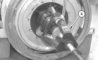
(4) Removal Tool 1U-6415
4. Attach tooling (4). Remove the bearing.
Illustration
g00615816
Illustration
g00615820
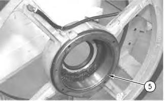
Illustration 9
g00615824
Replaceable bearing wear sleeve (inside view of end housing)
(5) Bearing wear sleeve
Some end housings have a bearing wear sleeve (4) which is replaceable.
Installation Procedure
To install the bearing that is located at the exciter end of the generator, use the following procedure.
1. Use a bearing induction heater in order to heat the bearing to 149 °C (300.2 °F).
2. While the bearing is 149 °C (300.2 °F), place the bearing on the shaft.
3. Install the generator end housing. If the generator end housing is equipped with a bearing cap, attach the bearing cap to the end housing. Install bolts and tighten the bolts.
4. If equipped, attach bearing lube line to the bearing cap.
5. If the generator end housing is equipped with retaining bars, attach the retaining bars to the end housing. Install the bolts and tighten the bolts.
Two-Bearing Generator
Note: On two-bearing generators, there is a bearing on each end of the generator. To install the bearing on the drive end of the generator, use the following procedure.
1. Use a bearing induction heater in order to heat the bearing to 149 °C (300.2 °F).
2. While the bearing is 149 °C (300.2 °F), place the bearing on the shaft.
3. Attach a hoist to the generator end housing. Attach the generator end housing to the generator. Install the bolts and tighten the bolts.
4. Attach the bearing cap to the end housing. Install the bolts and tighten the bolts.
5. If equipped, attach bearing lube line to bearing cap.
Copyright 1993 - 2024 Caterpillar Inc.
Rights Reserved.
Network For SIS Licensees. Wed Dec 18 09:25:56 UTC+0530 2024
Product: GENERATOR
Model: SR4 GENERATOR 9AB
Configuration: GENERATOR MOUNTED CONTROL PANEL EMCP II 9AB00001-UP
Disassembly and Assembly
SR4 Generator with VR3 or VR4 Voltage Regulator
Media Number -SENR3985-02
Publication Date -01/09/2003 Date Updated -23/09/2003
Coupling - Install
SMCS - 4456-012
Drive Hub Installation for Some Applications
Note: Not all applications require the information or installation fixture discussed in this procedure. Refer to Systems Operation, Test and Adjust, and Disassembly and Assembly, SENR5359, "Coupling - Remove" for drive hub location on the main rotor shaft.
i05193438
Use the following information in Illustration 1 only if your application requires the use of the stop fixture to provide location of the drive hub.
Table 1
TOOLS NEEDED
Tool Quantity
Stop Fixture. Refer to Illustration 1. 1
Make note of the position of the original drive hub. The important dimension is measured from the face of the drive hub flange to the (machined) face of the adaptor. If a new drive hub is used, ensure that dimension is the same as the original drive hub.
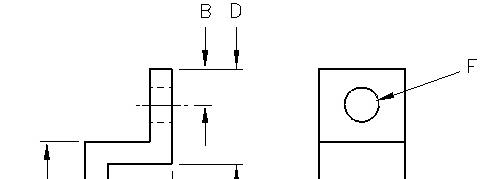
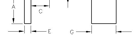
Illustration 1 g00615434
Stop fixture
(A) 114.3 mm (4.50 inch)
(B) 19.7 mm (0.78 inch)
(C) To be determined by measurement for the drive hub before removal for either the SR4B or the SR4 application.
(D) 50.8 mm (2.00 inch)
(E) 12.7 mm (0.50 inch)
(F) 19.1 mm (0.75 inch)
(G) 50.8 mm (2.00 inch)
Note: The drive hub is a heavy shrink fit installation.
1. Evenly heat the drive hub to 400 °C (752.0 °F). An oven is the preferred method for heating the drive hub.
Always wear protective gloves when handling parts that have been heated.
2. Place the drive hub on a work bench.
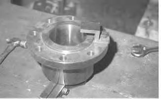
Illustration 2
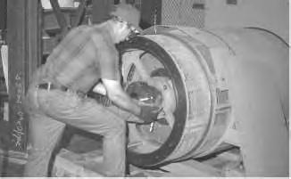
A drive hub with a stop fixture attached.
3. Attach the stop fixture to the drive hub.
3
4. Slide the drive hub on the rotor shaft. Continue to slide the drive hub until the stop fixture contacts the rotor shaft.
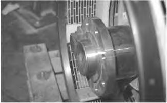
4
5. Remove the stop fixture from the drive hub.
g00615500
Illustration
g00615513
Illustration
g00615518
Drive Hub Installation for Other Applications
Drive Hub Installation
Installation Process with Torch
1. Allow the rotor shaft to cool completely to the ambient temperature after removal of the hub.
2. Clean all scratches, grooves, and imperfections on the shaft and on the hub carefully. The appropriate tools must be used to clean the inside diameter of the hub properly.
Note: This step assumes that the original drive hub will be installed again.
3. Install a link assembly on the drive hub to support the hub for installation.
4. Install the appropriate stop that will locate the hub properly upon installation onto the rotor shaft.
5. Use an appropriate lifting devise to place the drive hub at approximately the same height of the rotor shaft. (The lifting device will allow less distance for the hub to be moved after the heat is removed.) Refer to Illustration 5.
6. During drive hub installation, since there will be no direct flame on the main rotor shaft, a wet (cool/cold) towel can be wrapped around the rotor shaft, near the lip seal and shaft bearing. The towel will help reduce the heat exposure of the lip seal and bearing to the heat that is conducted from the drive hub through the rotor shaft.
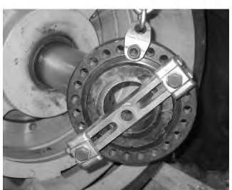
Illustration 5 g02164086
Drive hub example. The drive hub in this illustration is not from a SR4 or SR4B application.
7. Use one of the rose bud torches to heat the inside bore of drive hub. Constantly move the torch around the ID of the hub to heat the hub as evenly as possible. Monitor the external temperature of the hub with the infrared thermometer. Refer to Illustration 6.
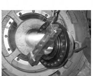
Illustration 6 g02164087
8. Once the external surface of the drive hub reaches approximately 371° C (700° F), the hub can be installed on the rotor shaft.
a. Any adjustments to the hub location must be done quickly.
b. After the hub is in place, the external temperature of the hub may continue to rise for a short time.
c. Once the external temperature dropped to 343° C (650° F), the hub will adhere to the rotor shaft.
9. After the drive hub is installed in the proper location, use directional fans to assist cooling the drive hub and rotor shaft.
Installation Process with Oven
Always wear protective gloves when handling parts that have been heated.
Allow the rotor shaft to cool to ambient temperature after removal of the hub.
1. Observe all safety information.
2. Clean all scratches, grooves, and imperfections on the shaft and on the hub carefully. The appropriate tools must be used to clean the inside diameter of the hub properly.
Note: This step assumes that the original drive hub will be installed again.
3. Install the appropriate stops that will provide the correct position for the drive hub upon installation.
Note: Correct drive hub location should have been recorded before the original hub was removed.
4. Evenly heat the hub to 370 °C (700 °F) for 2 to 3 hours. An oven is the preferred method for heating the hub.
Note: In order to minimize the loss of heat, the generator and the oven must be located near each other.
Note: During drive hub installation, since there will be no direct flame on the main rotor shaft, a wet (cool/cold) towel can be wrapped around the rotor shaft, near the lip seal and shaft bearing. The towel will help reduce the heat exposure of the lip seal and bearing to the heat that is conducted from the drive hub through the rotor shaft.
5. After the appropriate amount of preheat time, remove the drive hub from the oven and then slide the hub into the required position on the rotor shaft.
6. After the drive hub has cooled, remove the stops if used.
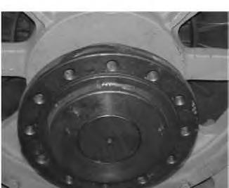
Illustration 7 g02164160 Typical example of drive hub installed
Product: GENERATOR
Model: SR4 GENERATOR 9AB
Configuration: GENERATOR MOUNTED CONTROL PANEL EMCP II 9AB00001-UP
Disassembly and Assembly
SR4 Generator with VR3 or VR4 Voltage Regulator
Coupling -
Remove
SMCS - 4456-011
Removal Procedure
Start By:
A. Remove the generator. Refer to Disassembly and Assembly, "Generator - Remove".
Table 1 TOOLS NEEDED
i01699927
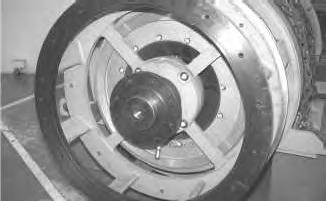
1. Simultaneously, heat the two opposite ends of the drive coupling. Use two acetylene torches that are equipped with rosebud tips. This method will quickly heat the coupling. Heat the coupling for three to five minutes. Do not overheat the coupling.
Always wear protective gloves when handling parts that have been heated.
2
2. Slide the coupling off the rotor shaft. Copyright 1993 - 2024 Caterpillar Inc. All Rights Reserved. Private Network For SIS Licensees. Wed Dec 18 09:27:07 UTC+0530 2024
Illustration
g00615513
Product: GENERATOR
Model: SR4 GENERATOR 9AB
Configuration: GENERATOR MOUNTED CONTROL PANEL EMCP II 9AB00001-UP
Disassembly and Assembly
SR4 Generator with VR3 or VR4 Voltage Regulator
Media Number -SENR3985-02 Publication Date -01/09/2003 Date Updated -23/09/2003
Coupling - Remove
SMCS - 4456-011
Two Bearing Flexible Coupling Removal
Start By:
i06188920
A. Remove the terminal box and generator if needed. Refer to Systems Operation Testing and Adjusting Disassembly and Assembly, SENR5359, "Generator - Remove" for a generic description to remove the terminal box and generator.
Note: The coupling may be serviced without the complete removal of the generator if desired. The generator can be pushed rearward on the generator set base rail. After the generator is pushed away from the engine, there should be enough clearance to service the coupling if desired.
Remove the Rubber in Shear Type of Coupling
Note: The flexible coupling does not require disassembly when removing the generator. The inner flexible element will slide out of the outer coupling ring as the generator is pushed away from the engine.
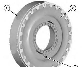
Illustration 1
Rubber in Shear Type Coupling
(1) Outer Ring
(2) Rubber Flexible Element
(3) Hardness Specification
1. Remove the outer ring mounting bolts for the coupling. If necessary, remove the outer ring of the coupling from the engine flywheel.
Note: Care must be taken in the process of removing the ring. The ring may need to be pried off.
2. Remove the mounting bolts for the inner member of the coupling. Carefully pry the rubber flexible element flange of the coupling from the generator hub.
Note: The coupling flexible element components weigh approximately 22.7 kg (50 lb). The outer ring weight is approximately 5 kg (11 lb).
Generator Drive Hub Removal
NOTICE
Care must be taken to avoid damage to the main rotor shaft of the generator.
Note: The drive hub is a heavy shrink fit installation. If the hub cannot be removed by heating, then the destructive method may be used.
The following procedure is written to provide information for the removal and installation of the drive hub (10) for the SR4 generators. The following procedure applies to two bearing generators.
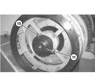
Illustration 2
(10) Drive hub machined face
(11) Main rotor shaft
g03327768
Always wear protective gloves when handling parts that have been heated.
The exact process and tooling for each application may vary. That is, the process that is documented in this publication was performed on a generator that was removed from the engine. If the generator is left on the generator base rails for servicing, the working distance will determine the puller assembly that can be used.
Even if the generator is moved away from the engine as far as possible, but left on the generator base rails, the working distance may not provide enough working space for the puller that is written about in this publication.
Important Safety Information
Work safely. Most accidents that involve product operation, maintenance, and repair are caused by failure to observe basic safety rules or precautions. An accident can often be avoided by recognizing potentially hazardous situations before an accident occurs.
A person must be alert to potential hazards. This person should also have the necessary training, skills, and tools in order to perform these functions properly.
Safety precautions and warnings are provided in this instruction and on the product. If these hazard warnings are not heeded, bodily injury or death could occur to you or to other persons. Caterpillar cannot anticipate every possible circumstance that might involve a potential hazard.
Therefore, the warnings in this publication and the warnings that are on the product are not all inclusive. If tools or procedures not recommended by Caterpillar are used, ensure that all of the tools and procedures are safe to use.
Ensure that the product will not be damaged or become unsafe due to the use of tools or procedures not recommended by Caterpillar.
The following warning must be heeded due the flames, gas, and heat of the process.
Personal injury or death can result from fumes, gases and ultraviolet rays from the weld arc.
Welding can cause fumes, burn skin and produce ultraviolet rays.
Keep your head out of the fumes. Use ventilation, exhaust at the arc, or both, to keep fumes and gases from your breathing area. Wear eye, ear and body protection before working.
Protect yourself and others; read and understand this warning. Fumes and gases can be dangerous to your health. Ultraviolet rays from the weld arc can injure eyes and burn skin. Electric shock can cause death.
Read and understand the manufacturer's instructions and your employer's safety practices. Do not touch live electrical parts.
See "American National Standard Z49.1, Safety in Welding and Cutting" published by the American Welding Society.
American Welding Society 2501 N.W. 7th Street Miami, Florida 33125
See "OSHA Safety and Health Standards, 29 CFR 1910", available from U.S. Department of Labor.
U.S. Department of Labor Washington, D.C. 20210
Specifications
The drive hub is considered to be a "heavy shrink" fit installation.
The 9S-8900 Double Acting Cylinder produces 311 N (70,930 lbs) of rod out force at rated 68.95 kPa (10,000 psi) input.
Note: Important. The hydraulic cylinder MUST have enough stroke to remove the drive hub without stopping once the drive hub breaks free of the rotor shaft. The stroke must be 152.4 mm (6 inch) to 203.2 mm (8 inch).
Recommendation
Due to the heat that is involved with the following process, the internal diameter of the drive hub can become warped. If the original drive hub is to be reused, the inside diameter of the drive hub must be checked. The inside diameter must be checked to verify if the inside diameter of the drive hub is true and round. The drive hub ID must maintain the original shrink fit. Caterpillar suggests that a new drive hub should be installed in place of the original.
Tooling
• A fire extinguisher that is ready to be used
• High heat gloves
• Appropriate eye and (full) face protection
• Welding jackets for arm protection
• 9S-8900 Double Acting Cylinder (152.4 mm (6 inch) to 203.2 mm (8 inch) of travel are necessary to remove the drive hub from the rotor shaft completely)
• 5P-2180 Puller (The 5P-2180 was modified with six new holes. The new holes match the bolt hole pattern of the SR5 drive hub.)
• 3S-6224 Electric Hydraulic Pump Gp (115 V)
• An appropriate lifting device that can support the weight of the drive hub, the adaptor, and the hydraulic assembly. (The drive hub weights approximately 70 lbs.)
• Optional - A weld blanket or heat shield to protect the front bracket from the heat of the rose bud tips
• Link assemblies (possibly used to support the drive hub during removal and installation)
• 251-0030 Infrared Thermometer
• Oxygen and acetylene tanks and associated equipment (hoses, gages, flint spark lighter, and tips)
Note: If available, propylene gas can be used in place of acetylene. Propylene gas has the capability of being a hotter gas than acetylene. Propylene gas can heat the drive hub to the necessary temperature in less time, which allows less heat transfer to the rotor shaft.
Preparation
1. Two qualified people are required to perform the process, three are preferred. Two people are needed to heat the drive hub while the third person operates the puller.
2. Prepare two torches equipped with "rose bud" tips. There must be enough oxygen and acetylene available to operate both tips for approximately 20 minutes.
3. A 120 VAC supply will be needed to operate the power pack for the hydraulic cylinder that is used for the puller.
Note: The 9S-8900 cylinder produces 311 N (70,930 lbs) of rod out force at rated 68.95 kPa (10,000 psi) input.
Drive Hub Position
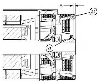
Make note of the position of the original drive hub (10) that is on the rotor shaft. The important dimension is measured from the face of the drive hub flange (20) to the (machined) face (21) of the adaptor. If a new drive hub is used, ensure that dimension "A" is the same as the original drive hub.
3
Typical generator example (20) Adaptor face (21) Drive hub face
g02163823
Tables 1, 2, and 3 shows the variety of drive hub locations for different serial numbers and applications.
Note: If there is a difference between the original measured distance of the drive hub from the face of the rotor shaft and the information that is in Table 1, use the measured distance for your application.
Illustration
Table 1
SR4 Generators
Type
SR4 683 5RA no 46.23 mm (1.82 inch) from end of shaft.
SR4 687 5VA no 46.23 mm (1.82 inch) from end of shaft.
SR4 804 8ZD no Flush with shaft end.
SR4 807 5ZA no Flush with shaft end.
SR4 807 3WF yes Flush with shaft end.
SR4 808 2ED yes
SR4 808 2ED yes
SR4 808 8ZL yes
23.9 mm (0.941 inch) from hub bolt face to close coupled adapter mounting bolt face.
23.9 mm (0.941 inch) from hub bolt face to close coupled adapter mounting bolt face.
23.9 mm (0.941 inch) from hub bolt face to close coupled adapter mounting bolt face.
SR4 809 6LA no 39.37 mm (1.55 inch) from machined face to end of shaft.
SR4 809 6LA no 39.37 mm (1.55 inch) from machined face to end of shaft.
SR4 809 8FD yes
SR4 809 2SM yes
23.9 mm (0.941 inch) from hub bolt face to close coupled adapter mounting bolt face.
23.9 mm (0.941 inch) from hub bolt face to close coupled adapter mounting bolt face.
SR4 809 4MD no
Flush with shaft end.
SR4 812 6WR no Flush with shaft end.
SR4 812 3BZ no
SR4 812 4SZ no
SR4 815 8MM no
SR4 815 3RD no
SR4 815 8MM yes
Table 2
SR4B Generators
Type Model Generator serial number prefix
SR4BGD 690
39.37 mm (1.55 inch) from machined face to end of shaft.
39.37 mm (1.55 inch) from machined face to end of shaft.
39.37 mm (1.55 inch) from machined face to end of shaft.
Flush with shaft end.
23.9 mm (0.941 inch) from hub bolt face to close coupled adapter mounting bolt face.
Is the drive hub keyed?
G5L, G5M, G5K, G5B, G5N, G4X, G5C, G5R, G4S, G5D, G5S no
SR4B 690 3EN, 3FN, 3HN, ABH, 2GM, 2DN, 4WN, ABM, 3BM, 2DM, 6SN, ABY, 4DM, 2FN, 7DN, ACA no
SR4B 820
2HN, AAY, AAD, A4A, AAR, AAJ, 1HN, 2SN, 7TN, AEB, 4GN, 9CN, AEZ, 2GZ, 8XS no
SR4BGD 820 G6X, G6S, G6W, G6T, G5J, G5Z, G4Z, G5J, G5A, G6C, G6R, G6F no
SR4B 860 8LZ, 6ZZ, 9GZ, 8PZ, 8TZ, 9DZ, 9WZ, 9XZ, 9MZ, 9RZ no
Drive hub location
49.784 mm (1.96 inch) from end of shaft to hub bolt circle.
46.228 mm (1.82 inch) from end of shaft to hub bolt circle.
46.228 mm (1.82 inch) from end of shaft to hub bolt circle
46.228 mm (1.82 inch) from end of shaft to hub bolt circle.
46.228 mm (1.82 inch)
Type
Table 3
SR4BHV Generators
Model Generator serial number prefix
Is the drive hub keyed?
SR4BHV 2400 AEY, AAL, AES, ABA, ABG, AEL, AEG, ACG, AEA, ACN, ACZ yes
SR4BHV 2600 A5A, A4Z, A4Y, A4X, PCP yes
SR4BHV 2700 G3N, G3R, G3S, G3T, G3W, G3X, G3Y, KHD, G4A, G4B yes
SR4BHV 2800 ABE, ADJ, ABT, ACB, ADB yes
Drive Hub Removal
from end of shaft to hub bolt circle.
Drive hub location
24.64 ± 0.76 mm (0.97 ± 0.03 inch) from hub bolt face to close coupled adapter mounting bolt face.
25.4 mm (1 inch) from hub bolt face to close coupled adapter mounting bolt face.
25.4 mm (1 inch) from hub bolt face to close coupled adapter mounting bolt face.
24.64 ± 0.76 mm (0.97 ± 0.03 inch) from hub bolt face to close coupled adapter mounting bolt face.
1. Separate the generator from the engine if needed. Refer to Systems Operation Testing and Adjusting Disassembly and Assembly, SENR5359, "Generator - Remove" for a generic description to remove the terminal box and generator.
2. Install the adaptor, puller assembly, and safety chains. Refer to Illustration 4.
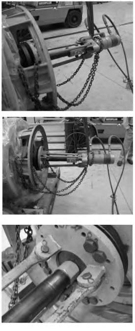
Illustration 4
g02163830
Typical example of modified tooling used for hub removal
3. Ensure that all of the mounting bolts for the adaptor are installed equally. The adaptor MUST be installed parallel to the drive hub. Proper installation will ensure that the load is distributed evenly between the mounting bolts. Proper installation will ensure that the puller assembly pulls evenly on the drive hub.
a. Ensure that the hydraulic cylinder is fully retracted.
b. Keep the puller assembly aligned with the drive hub and rotor shaft.
c. Ensure that the puller assembly is supported by an appropriate lifting device.
4. Apply pre-load pressure to the puller assembly to allow the assembly to remain in place prior to heating the drive hub. 20.7 kPa (3,500 psi) input was used. Therefore, the puller was producing approximately 106.8 N (24,825 lbs) of rod out force.
5. Check that the puller assembly is aligned and safe.
6. If desired, install a weld blanket or heat shield to protect the front bracket, rotor shaft, shaft lip seal, and bearing from excessive heat.
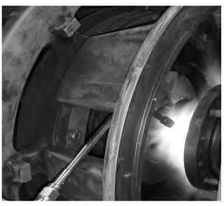
7. From opposite sides of the adaptor, simultaneously begin to heat ONLY the backside of the drive hub at the base of the flange. Apply the heat as evenly as possible by constantly moving the rose bud tips around the drive hub. Refer to Illustration 5.
Note: Keep heat away from the hydraulic cylinder of the puller and away from the generator rotor shaft.
8. Ensure that the pressure on the drive hub remains constant.
9. The drive hub should break free of the rotor shaft in approximately 4 to 8 minutes.
Note: The time variation depends on the ambient temperature, the shrink fit of the hub, how well the heat is evenly applied, and the amount of heat that is applied to the drive hub.
Note: The external temperature of the drive hub will exceed 315° C (600° F) to 371° C (700° F).
10. Once the hub breaks free of the rotor shaft, continue to heat the hub and continue to apply pressure with the puller until the hub is removed from the rotor shaft completely.
Illustration 5 g02163877
This is the sample of the manual click on the download link for completemanual
DOWNLOAD LINK
For some reason if link does not work download this pdf and then click