



Product: ROAD RECLAIMER
Model: RR-250B ROAD RECLAIMER 3RR
Configuration: SS-250B Soil Stabilizer RR-250B Road Reclaimer 3RR00001-UP (MACHINE) POWERED BY 3406C Engine
Disassembly and Assembly
RR-250B ROAD RECLAIMER AND SS-250B SOIL STABILIZER POWER TRA
Media Number -KENR1872-00 Publication Date -27/02/1997
Axle
SMCS - 3278-015
Disassemble Axle Housing
Date Updated -10/10/2001
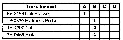
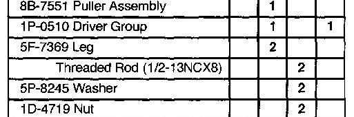
Start By:
a. remove axle.
b. remove planetary wheel ends.
c. remove brakes.
d. remove brake chamber
e. remove steering knuckle
f. remove spindle hub assembly
1. Support the axle housing and transmission group on a suitable stand.
2. Drain the oil from the axle housing and the transmission.
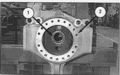
3. Remove one seal (1) from each end of the axle housing (2).
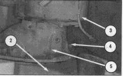
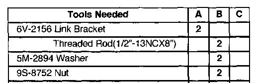
4. Attach Tooling (A) and a suitable lifting chain to transmission (3).
5. Remove twelve nuts and washers (4).
6. Remove carrier housing (5) and transmission group (3) together from axle housing (2). The weight of carrier housing (5) and transmission group (3) is 181 kg (400 lbs).
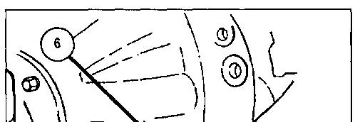
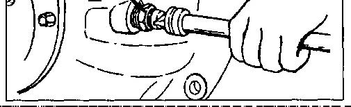
7. Support carrier housing (5) and transmission group (3) in a suitable stand.
8. Loosen the locknut and back off thrust screw (6).
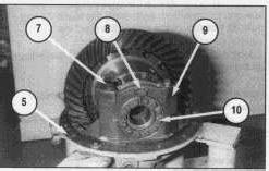
9. Place adjacent marks on bearing cap (9) and on the carrier legs of carrier housing (5) to aid in assembly.
10. Remove two cotter pins (8).
11. Remove four bolts (7).
12. Remove two bearing caps (9).
13. Remove two adjusting nuts (10).
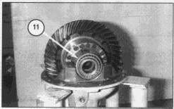
14. Remove two bearing cups (11).
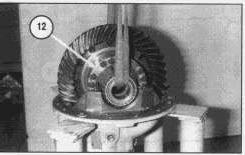
15. Install a lifting strap and remove carrier (12). The weight of carrier (12) is 35 kg 80 lb).
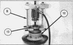
16. Install Tooling (B) and remove bearing cone (13) from the upper half of carrier (12).
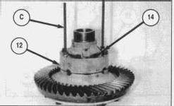
17. Remove two bolts (14), opposite each other, and install Tooling (C) as shown. Tighten the nuts on tooling (C) as shown. Remove the remaining bolts (14).
This is the sample of the manual click on the download link for complete manual
DOWNLOAD LINK
For some reason if link does not work download this pdf and then click
The upper half of carrier (12) holds a spring under compression. To prevent possible personal injury, remove the nuts on Tooling (C) slowly and evenly to release the spring pressure.
18. Back off the nuts in Tooling (C) until the spring pressure is released from the upper carrier (3).
NOTE: Put adjacent marks on the upper and lower halves of carrier (12) to aid in assembly.
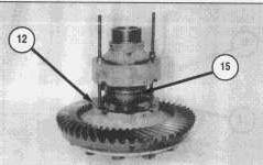
19. Remove the upper half of carrier (12). Remove differential assembly (15).
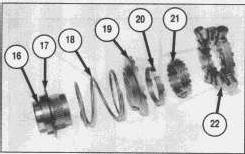
20. Upper half of differential assembly removed. The complete differential assembly consists of:
* two side gears (16)
* two spring retainers (17)
* two springs (18)
* two driven clutches (19)
* two holdout rings (20)
* one center cam (21)
* one spider (22).
NOTE: The differential assembly is the same on one side of spider (22) as it is on the other side (symmetrical). Only one side is shown.
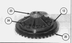
21. Attach tooling (B). Remove bearing cone (23) in the same way bearing cone (13) was removed.
22. Remove twelve nuts (24), washers and bolts.
23. Separate the lower half of carrier (12) from ring gear (25).
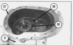
NOTE: At this point, the transmission must be disassembled down to inner case half (27) as shown. Refer to the "Transmission Disassemble & Assemble" section of this manual.
24. Remove eight bolts (26) and washers.
25. Remove lip seal (28).
26. Separate inner transmission case half (27) from carrier housing (5).
NOTE: Shims (39), not shown, are located between inner transmission case half (27) and carrier housing (5). Retain the original thickness for assembly.
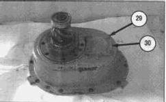
27. Remove four bolts (29) and washers.
28. Remove cover (30).
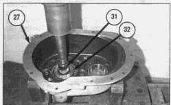
29. Press gear set (pinion) (31) from inner transmission case half (27). Bearing cone (32) is pressed from gear set (pinion) (31) at this time also.
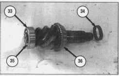
30. Remove the following parts from gear set (pinion) (31): * bearing (33)
* bearing preload spacer (34)
* retaining ring (35)
* bearing cone (36).
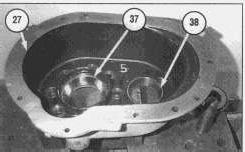
31. Remove two bearing cup races (37). One from each side of inner transmission case (27).
32. Use a press and Tooling (D) to remove bearing cup race (38). Copyright 1993 - 2024 Caterpillar Inc.
Tue Jun 18 23:07:46 UTC+0530 2024
Product: ROAD RECLAIMER
Model: RR-250B ROAD RECLAIMER 3RR
Configuration: SS-250B Soil Stabilizer RR-250B Road Reclaimer 3RR00001-UP (MACHINE) POWERED BY 3406C Engine
Disassembly and Assembly
RR-250B ROAD RECLAIMER AND SS-250B SOIL STABILIZER POWER TRA
Media Number -KENR1872-00 Publication Date -27/02/1997
Date Updated -10/10/2001 Axle
SMCS - 3278-016
Assemble Axle Housing
NOTE: Inspect all parts for wear or damage, and make replacements if needed as needed.
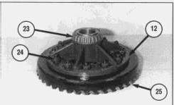
1. Install ring gear (25) on carrier (12), and install twelve nuts and bolts (24).
Tighten the nuts on bolts (24) to the appropriate torque listed for:
1/2-20 NF 115 to 156 N·m (85 to 115 lb ft).
5/8-18 NF 244 to 312 N·m (180 to 230 lb ft)
2. Heat bearing cone (23) to a maximum temperature of 135° C (275° F). Install bearing cone (23) on carrier (12).
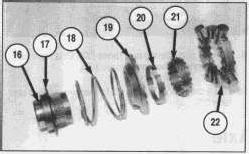
3. Prepare the differential assembly. The differential assembly consists of:
* two side gears (16)
* two spring retainers (17)
* two springs (18)
* two driven clutches (19)
* two holdout ring (20)
* one center cam (21)
* one spider (22).
NOTE: The differential assembly is the same on one side of spider (22) as it is on the other side (symmetrical). Only one side is shown.
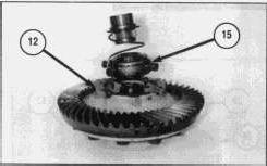
4. Install differential assembly (15) into the lower half of carrier (12) as shown.
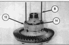
5. Position the upper half of carrier assembly (12) on the lower half of assembly (12).
The upper half of carrier (12) holds a spring (18) under compression. To prevent possible personal injury, remove the nuts on Tooling (B) slowly and evenly to release the spring pressure.
NOTE: Make sure the identification marks on the upper and lower carriers are in alignment.
6. Use Tooling (B) to compress the springs in the differential assembly.
7. Install bolts (14) that hold the upper and lower carrier (12) together. Tighten bolts (14) to a torque of 115 to 156 N·m (85 to 115 lb ft).
8. Remove Tooling (B), and install the remaining two bolts. Tighten the bolts to a torque of 115 to 156 N·m (85 to 115 lb ft).
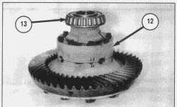
9. Heat bearing cone (13) to a maximum temperature of 138° C (275° F). Make sure bearing cone (13) is seated on the shoulder of carrier (12).
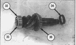
10. Install the following parts on gear set (pinion) (31):
* heat bearing cone (36) to a maximum temperature of 138° C (275° F). Install bearing (36). Make sure bearing cone (36) is seated on the shoulder of gearset (31).
* bearing preload spacer (34)
* retaining ring (35)
* heat bearing cone (33) to a maximum temperature of 138° C (275° F). Install bearing (33).
Make sure bearing cone (33) is seated on the shoulder of gearset (31).
NOTE: Bearing spacer (34), sets the preload on the gearset bearings. Refer to Step (15) for the preload procedure.
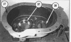
11. Use a press and Tooling (C) to install two bearing cup races (37) and 38. One from each side of inner transmission case (27).
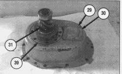
12. Install four bolts and washers (29). Use 7M-7260 Liquid Gasket on mating surfaces. Install cover (30).
13. Install gear set (pinion) (31). Bearing cone (32) is pressed from gear set (pinion) (31) at this time also.
NOTE: The thickness of shims (39) determines the depth of gear set (pinion) (31) into the carrier housing as it relates to ring gear (25).
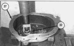
14. Heat bearing cone (31) to a maximum temperature of 138° C (275° F) and install.
15. Pinion gearset bearing preload procedure:
a. Put inner transmission case (27) in a press as shown, with gearset (pinion) (31) to the bottom.
NOTE: Do not install lip seal (28) at this time. Continue with adjusting the preload of the pinion bearings.
b. Install a sleeve of the correct size against bearing cone (32), as shown.
c. Apply and hold 24500 kg (54000 lbs) of pressure to the pinion bearings. As pressure is applied, rotate gearset (pinion) (31) several times so that the bearings make normal contact.
NOTE: The preload on the pinion bearing, if installing new bearings, should be .56 to 5.08 N·m (5 to 45 lb in). If installing used bearings set the preload to 1.13 to 3.39 N·m (10 to 30 lb in).
d. While pressure is held against the assembly, wind a cord around the bearing shaft or a similar diameter attached to the shaft, several times.
e. Attach a spring scale to the end of the cord.
f. Pull the cord with the scale on a horizontal line. As the bearing cage rotates, read the value on the scale. Make a note of the reading.
NOTE: Do not read the starting torque. Read only the torque value, after the cage starts to rotate. The starting torque will give a false reading.
g. Measure the diameter, where the cord was wound.
h. Divide this dimension in half to get the radius. Make a note of the radius dimension.
i. Use the following procedure to calculate the bearing preload.
j. kg (lbs) pulled × radius = preload.
k. Example: 3.4 kg (7.5 lbs) pulled × 8.4 cm (3.31 in) radius = 2.8 N·m (24.8 lb in).
l. If the preload of the pinion bearings is not within specification, do the following procedure, then repeat Steps a - i.
m. To increase the bearing preload, install (a thinner) bearing spacer (34). To decrease the bearing preload, install (a thicker) bearing spacer (34).
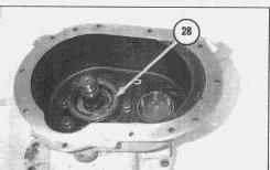
16. After the gearset (pinion) preload is correct, install lip seal (28).
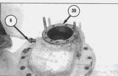
17. Gearset (pinion) (31) depth adjusting procedure:
Adjust the thickness of shims (39) for obtaining the correct pinion depth (depth of pinion shaft) as it relates to ring gear (26).
* Note thrust screw (6) backed out.
* Note alighnment studs.
a. Use a micrometer to measure the thickness of shims (39) that were originally removed from between inner transmission case half (27) and carrier housing (5). Record the measurement for later use.
b. Look for the pinion cone ("PC") variation number, location X, on the old pinion shaft that is being replaced. Record the number for later use. If the ("PC") variation number cannot be located, assemble the pinion shaft with a shim pack thickness obtained in step a.
NOTE: The ("PC") variation number can be either 100ths of a millimeter or 1,000ths of an inch. PC+.03, PC-.03 equals +.03 or -.03 millimeters respectively. PC+3, PC-3 equals +.003 or -.003 inches respectively.
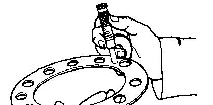

NOTE: The value calculated in step c or d is the thickness of the standard shim pack, without a variation.
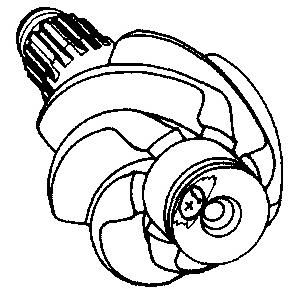
c. If the ("PC") variation number on the old pinion shaft is a plus (+), subtract the number from the original shim pack thickness that was measured in step a.
d. If the ("PC") variation number on the old pinion shaft is a minus (-), add the number from the original shim pack thickness that was measured in step a.
e. Look for the pinion cone ("PC") variation number, location X, on the new pinion shaft that is being installed. Record the number for later use.
NOTE: The value calculated in step f or g is the thickness of the new shim pack that will be installed.
f. If the ("PC") variation number on the new pinion shaft is a plus (+), add the number from the standard shim pack thickness that was measured in steps c or d.
g. If the ("PC") variation number on the new pinion shaft is a minus (-), subtract the number from the standard shim pack thickness that was measured in steps c or d.
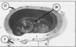
18. After preload on gearset (pinion) (31) and the depth of gearset (pinion) (31) in relationship to ring gear (25) is determined, assemble inner transmission case half (27) and carrier housing (5). Use 7M7260 Liquid Gasket on the mating surfaces.
19. Install eight bolts (26) and washers. Tighten the eight bolts to a torque of 175 to 225 N·m (130 to 165 ft lb).
NOTE: At this point, the transmission can be assembled. Refer to the Transmission Assemble section of this manual.
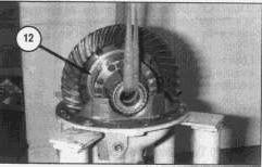
20. Use a lifting strap as shown and install carrier (12). The weight of carrier (12) is 35 kg 80 lb)
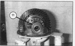
21. Install two bearing cups (11).
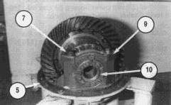
22. Install two bearing caps (9). Align adjacent marks on bearing cap (9) and the carrier legs of carrier housing (5) that were made at disassembly.
23. Install two adjusting nuts (10).
24. Install four bolts (7). The bolts seven to a torque of 366 to 475 N·m (270 to 350 lb ft).
25. Turn both adjusting nuts (10) hand tight against the bearings. Do not install cotter pin (8) until Step 44.
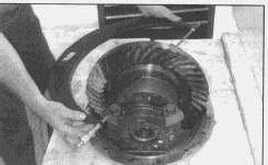
26. Use a large micrometer to measure the distance between (across corners) opposite surfaces of bearing caps (9). Make a note of both measurements.
27. Tighten each bearing nut (10), one notch. Measure across corners again. Compare the dimension with the distance across corners measured in Step 26. The difference between the two dimensions is the amount the bearing caps have expanded. Continue to adjust the adjusting rings one notch at a time, measuring after each adjustment until the expansion between bearing caps is between .15 to .33 mm (.006 to .013 in.)
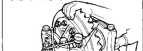
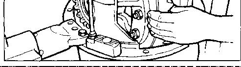
28. Attach a dial indicator on the mounting flange of carrier (5), as shown.
29. Adjust the dial indicator so that the plunger or pointer is against the back surface of the ring gear.
30. Adjust the dial of the indicator to zero (0).
31. Rotate ring gear (25) while you read the dial indicator. The runout of the ring gear must not exceed .20 mm (.008 in).
NOTE: If the runout of the gear exceeds specifications, remove the ring gear assembly from the carrier. Check the differential parts, including the carrier for the problem that causes the runout of the gear to exceed specifications. Repair or replace parts, as necessary.
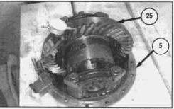
32. Attach a dial indicator to the mounting flange of carrier (5), as shown.
33. Adjust the dial indicator so that the plunger or pointer is against the tooth surface of ring gear (25).
34. Adjust the dial of the indicator to zero (0).
35. Hold gear set (pinion) (31) in position.
36. While you read the dial indicator, rotate ring gear (25) a small amount in both directions, against the teeth of gear set (pinion) (31). The back lash should read between .25 to .51 mm (.010 to .020 in).
37. If the backlash is not within specification adjust as needed.
NOTE: Backlash is increased by moving the ring gear away from the pinion; and decreased by moving it closer.
38. Loosen one bearing adjuster one notch, then tighten the opposite adjuster the same amount. Repeat until the backlash is within specification.
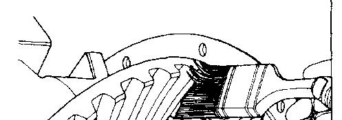
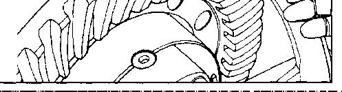
39. Apply a marking compound to approximately 12 gear teeth of ring gear (25). Rotate ring gear (25) so that the twelve teeth are next to the pinion.
40. Rotate ring gear (25) forwards and backwards so that the twelve teeth go past gear set (pinion) (31), at least six times, to get a good contact pattern.
41. Look at the contact patterns on the ring gear teeth. Compare the pattern to the next three illustrations.
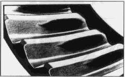
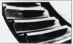
Ring gear contact pattern. High pattern.
42. A high contact pattern indicates that gear set (pinion) (31) was not installed deep enough into ring gear (25). To correct a high contact pattern, remove the shims from the pinion that were installed in Step 17.
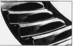
Ring gear contact pattern. Low pattern.
43. To correct a low contact pattern, add shims to gear set (pinion (31).
44. After all adjustments are within specification, install cotter pin (8).
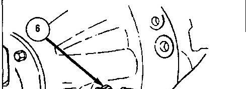
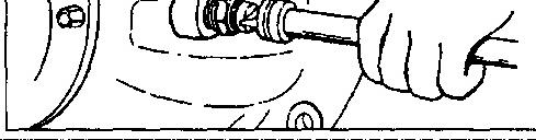
45. Install thrust screw (6) and locknut. Thread thrust screw (6) in until it touches ring gear (25), then loosen thrust screw (6) 1/2 (one half) turn.
46. Tighten the locknut to a torque of 200 N·m (150 lb ft).
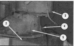
47. Attach Tooling (A) and a suitable lifting chain to transmission (3). Use 8T-9022 General Purpose Adhesive Sealant and apply to the mating surfaces.
48. Install carrier housing (5) and transmission group (3) together to axle housing (2). The weight of carrier (5) and transmission group (3) is 181 kg (400 lbs).
49. Install twelve nuts (4) and washers. Tighten the nuts to a torque of:
1/2 - 20 NF ... 100 to 150 N·m (75 to 115 ft lb)
5/8 - 18 NF ... 200 to 300 N·m (150 to 230 ft lb)
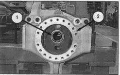
50. Install one seal (1) in each end of the axle housing (2).
End By:
a. install axle.
b. install planetary wheel ends.
c. install brakes.
d. install brake chamber
e. install steering knuckle
f. install spindle hub assembly
Copyright 1993 - 2024 Caterpillar Inc. All Rights Reserved. Private Network For SIS Licensees. Tue Jun 18 23:07:57 UTC+0530 2024
Product: ROAD RECLAIMER
Model: RR-250B ROAD RECLAIMER 3RR
Configuration: SS-250B Soil Stabilizer RR-250B Road Reclaimer 3RR00001-UP (MACHINE) POWERED BY 3406C Engine
Disassembly and Assembly
RR-250B ROAD RECLAIMER AND SS-250B SOIL STABILIZER POWER TRA
Media Number -KENR1872-00 Publication Date -27/02/1997 Date Updated -10/10/2001
Axle
SMCS - 3278-010
Remove & Install Axle Housing
Start By:
a. remove wheels.
b. remove propel motor.
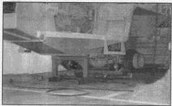
1. Support the machine with suitable blocking equipment. Support the machine under the frame as shown.
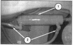
2. Mark hydraulic lines (2) for identification at assembly. Disconnect two hydraulic lines (2) from two steering cylinders (1). Cap and plug the open connections.
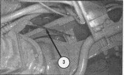
3. Disconnect transmission shifting cable (3) from the transmission and loosen the nuts and remove the cable from the bulkhead fastener.
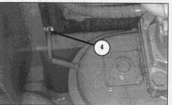
4. Disconnect two wire connectors (4).
Use some method to lock the axle position firmly to the jack before removal of the axle mounting bolts. This axle is not perfectly balanced and any rotation of the axle due to this imbalance could cause the axle to roll off the jack, causing possible injury to personnel or to the axle.
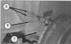
5. Purge the air system of pressurized air. Disconnect two air lines (5) from both ends of axle (7).
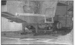
6. Secure axle (7) firmly to a transmission jack or fork jack and remove (from both ends) the four nuts and bolts (6) that mount the axle to the machine frame.
7. Lower axle (7), and remove axle from the underneath of the machine.
8. For installation of the axle, reverse the the removal steps.
End By:
a. install wheel and tire assemblies.
b. install propel motor.
Copyright 1993 - 2024 Caterpillar Inc. All Rights Reserved. Private Network For SIS Licensees. Tue Jun 18 23:07:33 UTC+0530 2024
Product: ROAD RECLAIMER
Model: RR-250B ROAD RECLAIMER 3RR
Configuration: SS-250B Soil Stabilizer RR-250B Road Reclaimer 3RR00001-UP (MACHINE) POWERED BY 3406C Engine
Disassembly and Assembly
RR-250B ROAD RECLAIMER AND SS-250B SOIL STABILIZER POWER TRA
Media Number -KENR1872-00
Brake Chamber
SMCS - 4115-010
Publication Date -27/02/1997
Date Updated -10/10/2001
Remove And Install Brake Chamber
Start By:
a. remove wheel and tire assembly
b. remove planetary wheel ends.
1. Release the brakes.
Reference: For information on releasing the brakes refer to the RR-250B And SS-250B Operation and Maintenance Manual, Form No. KEBU6890.
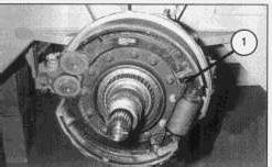
2. Remove brake spring return spring (1).
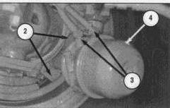
3. Purge the air system of pressurized air. Disconnect two air lines (3).
4. Remove two bolts and two nuts (2) and washers. Tighten the bolts and nuts to a torque of 115 to 155 (85 to 115 lb ft) at assembly.
5. Remove brake chamber (4).
NOTE: For installation of the brake chamber, reverse the removal steps.
End By:
a. install wheel and tire assembly.
b. remove planetary wheel ends.
Copyright 1993 - 2024 Caterpillar Inc. All Rights Reserved. Private Network For SIS Licensees.
Product: ROAD RECLAIMER
Model: RR-250B ROAD RECLAIMER 3RR
Configuration: SS-250B Soil Stabilizer RR-250B Road Reclaimer 3RR00001-UP (MACHINE) POWERED BY 3406C Engine
Disassembly and Assembly
RR-250B ROAD RECLAIMER AND SS-250B SOIL STABILIZER POWER TRA
Media Number -KENR1872-00 Publication Date -27/02/1997 Date Updated -10/10/2001
Brakes
SMCS - 4001-010
Remove And Install Brake Assembly
Start By:
a. remove wheel and tire assembly.
b. remove planetary wheel end.
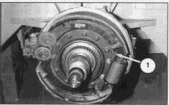
1. Disconnect brake shoe return spring (1).
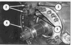
2. Remove two retaining rings (2) and washers.
3. Remove the lockwire between bolts (5).
This is the sample of the manual click on the download link for complete manual
DOWNLOAD LINK
For some reason if link does not work download this pdf and then click