PS-150C Pneumatic Compactor
Note: Use Bookmarks panel to navigate
Product: PNEUMATIC COMPACTOR
Model: PS-150C PNEUMATIC COMPACTOR FPS
Configuration: PS-150C Pneumatic Compactor FPS00001-UP (MACHINE) POWERED BY 3054T Engine
Disassembly and Assembly
PS-150C PNEUMATIC COMPACTOR MACHINE SYSTEMS
Media Number -KENR7076-00
Publication Date -01/05/2005
Axle
SMCS - 3258-010; 3258-015; 3258-016
Remove & Install Axle
Start By:
a. remove rear wheel and tire assembly
b. remove water spray bar
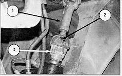
1. Remove the bolts and straps (2). Remove drive shaft (1) from the yoke.
2. Remove the bolt and washer from the center of yoke (3).
3. Remove yoke (3) from the center of the axle.
Date Updated -22/01/2016
KENR70760008
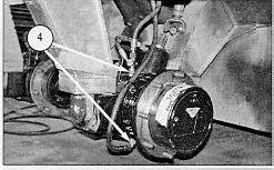
4. Disconnect hose assemblies (4) from the axle.
5. Position a suitable floor jack under the axle. Secure the axle to the floor jack.
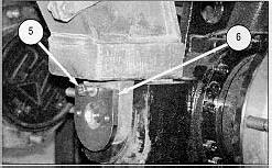
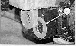
6. Remove two bolts (5) (one from each side). Remove two pins (6) and shims (7) (one from each side). Lower the floor jack and remove the axle from under the machine. The weight of the axle is approximately 120 kg (264 lb).
NOTE: For installation of the axle, reverse the removal steps.
NOTE: Apply 4C-5597 Anti-Seize to pins (6) during assembly.
Disassemble Axle
Start By:
a. remove axle
DOWNLOAD LINK
For some reason if link does not work download this pdf and then click
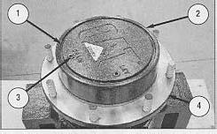
1. Remove plug (3) from cover (2). Remove retaining ring (1) and cover (2) from output housing (4).
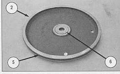
2. Remove O-ring seal (5) and thrust button (6) from cover (2). Check O-ring seal (5) for wear or damage, and replace if necessary.
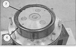
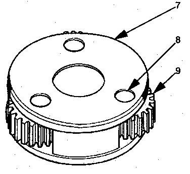
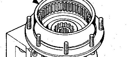
3. Remove carrier assembly (7) from output housing (4).
4. Use the following procedure to disassemble carrier assembly (7).
a. Remove the end plate.
b. Drive pin (8) from the planetary carrier. Remove planetary gear (9), the two thrust washers and the 54 needle bearings from the planetary carrier.
c. Repeat Step b for the remaining two planetary gears.
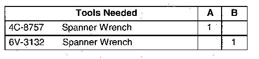
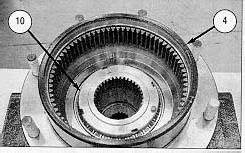
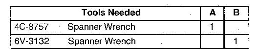
NOTE: There are different size ring nuts for each half of the final drive. Use either Tooling (A) or Tooling (B) to remove ring nut (10).
5. Use the Tooling (A) or (B) to remove ring nut (10) from output housing (4).
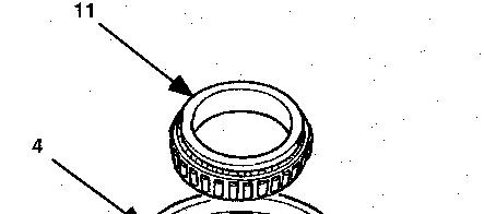
6. Use a suitable puller to remove output housing (4) and bearing cone (11) from the hub.
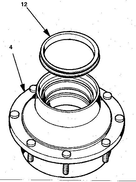
7. Remove duo-cone seal (12) from output housing (4).
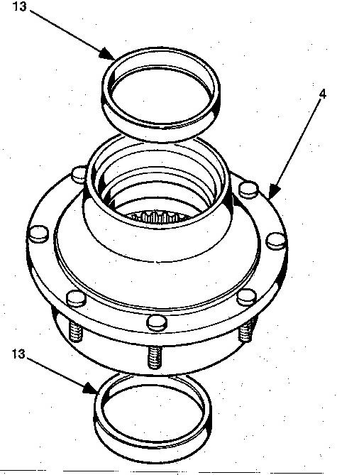
8. Remove two bearing cups (13) from output housing (4).
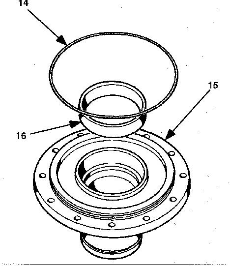
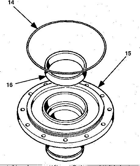
9. Remove O-ring seal (14) and bearing cup (16) from hub (15).
10. Repeat steps 1 through 9 for the other hub.
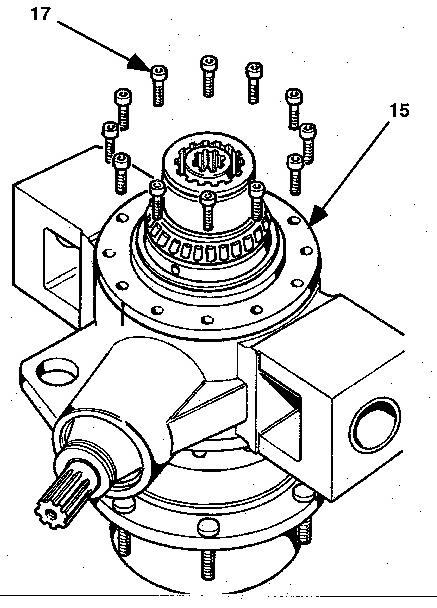
NOTE: In order to maintain correct orientation of the lubrication holes, mark the hub (15) and the housing before the hub is removed.
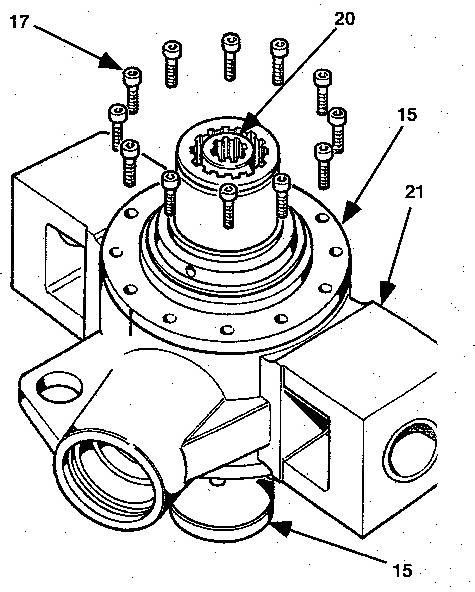
11. Remove 12 bolts (17) and remove hub (15) from the housing.
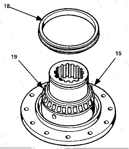
12. Remove the duo-cone seal (18) and bearing cone (19) from hub (15).
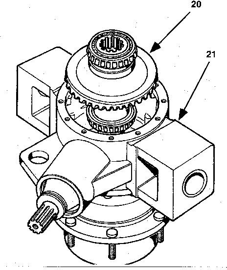
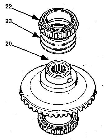
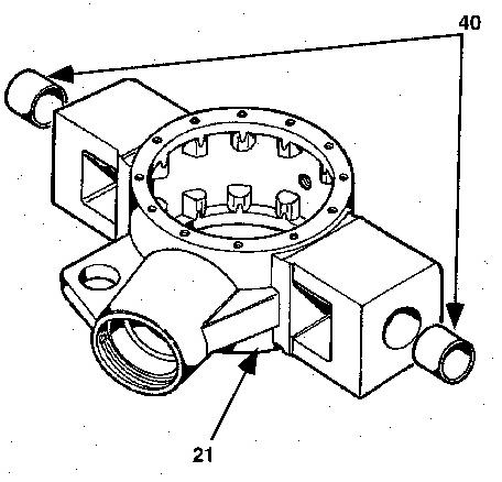
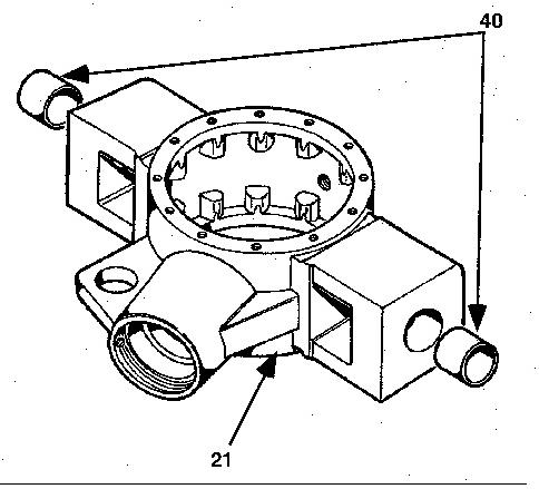
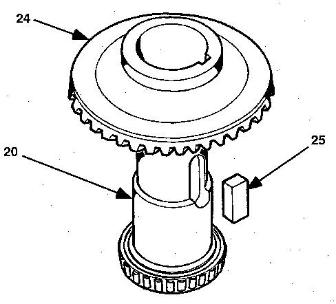
13. Remove output shaft and bevel ring gear assembly (20) from housing (21).
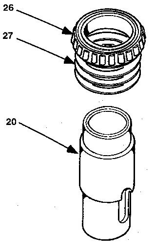
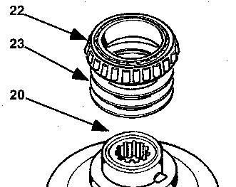
14. Remove bearing cone (22) and shims (23) from output shaft (20).
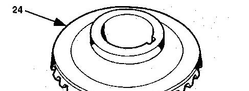
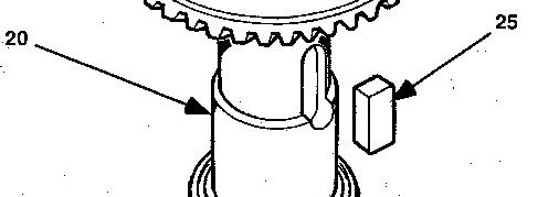
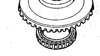
15. Remove bevel ring gear (24) and key (25) from output shaft (20).
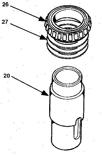
16. Remove bearing cone (26) and shims (27) from output shaft (20).
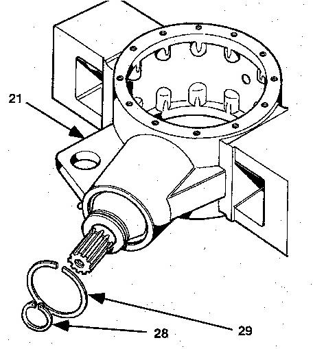
17. Remove retaining ring (28) from the input shaft.
18. Remove retaining ring (29) from housing (21).
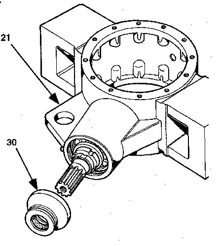
19. Remove cover (30) from housing (21).
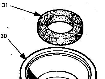
20. Remove seal (31) from cover (30).
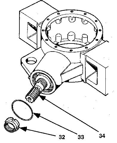
21. Remove O-ring seal (33) from the housing.
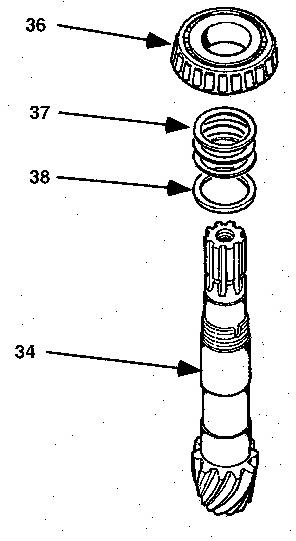
22. Remove locknut (32) from input shaft (34).
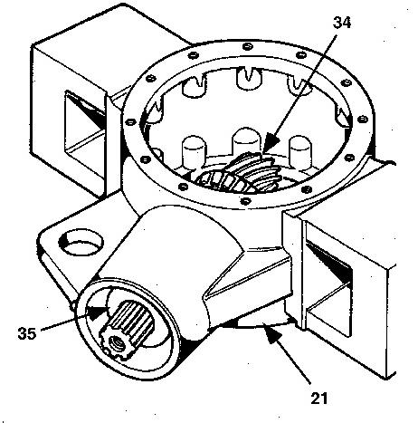
23. Remove input shaft (34) and bearing cone (35) from housing (21).
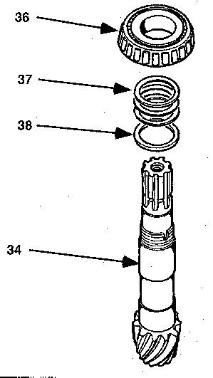
24. Remove bearing cone (36), shims (37) and spacer ring (38) from input shaft (34).
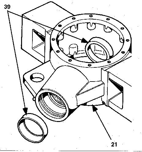
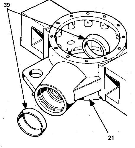
25. Remove bearing cups (39) from housing (21).
26. Remove bushings (40) from housing (21).
Assemble Axle
1. Install bushings (40) in housing (21).
2. Install shims (27) and bearing cone (26) on output shaft (20).
3. Install key (25) and bevel ring gear (24) on output shaft (20).
4. Install shims (23) and bearing cone (22) on output shaft (20).
5.
Install bearing cup (16) and O-ring seal (14) in both hubs (15).
6. Position lower hub (15) on housing (21), and install 12 bolts (17). Make sure the orientation marks are aligned.
7. Position output shaft and bevel ring gear assembly (20) in the housing (21).
8. Position remaining hub (15), and install 12 bolts (18). Make sure the orientation marks are aligned.
9. Check the output bearing preload by measuring the rotating torque of the output shaft. The reading should be between 0.34 to 0.57 N·m (3.0 to 5.0 lb in). The rotating torque (bearing preload) can be changed by either adding or removing the shims under the bearing cones on the output shaft.
10. Remove 12 bolts (17), and remove upper hub (15) from housing (21).
11. Remove output shaft and bevel ring gear assembly (20) from housing (21).
12. Install spacer ring (38), shims (37), and bearing cone (36) on input shaft (34).
13. Install bearing cups (39) in housing (21).