DOWNLOAD LINK
For some reason if link does not work download this pdf and then click
Product: COLD PLANER
Model: PM820 COLD PLANER TLZ
Configuration: PM820 Cold Planer TLZ00001-UP (MACHINE) POWERED BY C18 Engine
Disassembly and Assembly
PM820, PM822, and PM825 Cold Planer Machine Systems
Media Number -M0082957-05
Access Door - Remove and Install - Rotor Chamber
SMCS - 7273-010-AO; 7273-010-HK
Removal Procedure
Start By:
a. Remove the right-hand side plate. Table 1
1. Fully lower the moldboard. Refer to Operation & Maintenance Manual, "Operator Controls" , Moldboard Lower/Float and Rotor Door Close
2. Fully lower the anti-slab. Refer to Operation & Maintenance Manual, "Operator Controls" , Anti-Slab Lower/Float
3. Use suitable cribbing to support the rotor assembly. The weight of the rotor assembly is approximately 3400 kg (7500 lb)
4. Turn the battery disconnect switch to the OFF position.
i07112007
Illustration 1
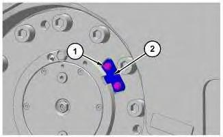
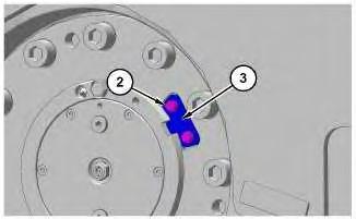
5. Remove two bolts (1). Remove plate (2).
Illustration 2
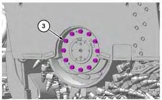
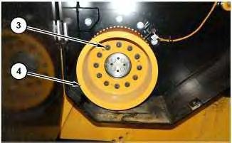
6. Remove 12 bolts (3).
g06132821
Illustration 3
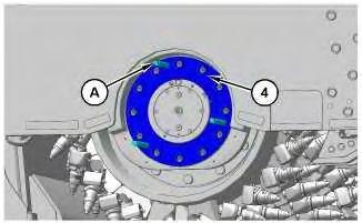
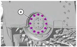
7. Install tooling (A) as shown. Use tooling (A) to remove flange (4).
g06132819
g06133031
4
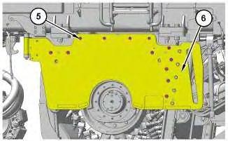
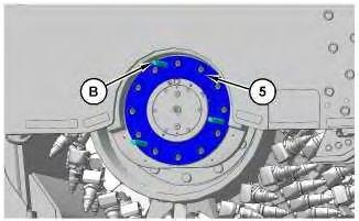
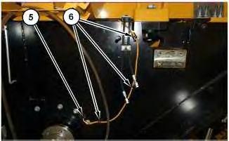
8. Remove 12 bolts (5). Open rotor chamber access door (6).
5
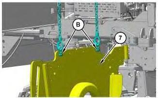
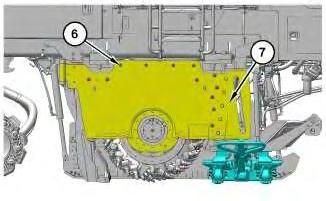
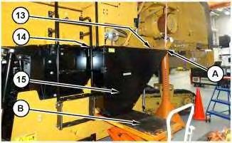
9. Attach Tooling (B) and a suitable lifting device to support the weight of rotor chamber access door (7). The weight of rotor chamber access door (7) is approximately 350 kg (772 lb).
Illustration 6
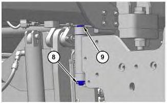
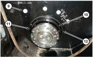
10. Remove cotter pin (8). Remove retaining pin (9).
Illustration
g06133157
Illustration
g06228838
g06228840
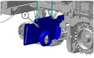
11. Remove rotor chamber access door (7).
Installation Process
1. Install rotor chamber access door (7) in the reverse order of removal.
Copyright 1993 - 2025 Caterpillar Inc. All Rights Reserved. Private Network For SIS Licensees.
Tue Mar 11 10:01:17 UTC+0700 2025
Product: COLD PLANER
Model: PM820 COLD PLANER TLZ
Configuration: PM820 Cold Planer TLZ00001-UP (MACHINE) POWERED BY C18 Engine
Disassembly and Assembly
PM820, PM822, and PM825 Cold Planer Machine Systems
Media Number -M0082957-05 Publication Date -01/12/2019 Date Updated -03/12/2019
Antislab - Remove and Install
SMCS - 670S-010
Removal Procedure
Start By:
a. Remove the first stage conveyor.
b. Remove the right-hand side plate.
Table 1
Required Tools Tool Part Number
A 463-3380 Lift As 1
B 154-6185 Forcing Bolt 3
1. Fully lower the moldboard. Refer to Operation & Maintenance Manual, "Operator Controls" , Moldboard Lower/Float and Rotor Door Close
2. Use suitable cribbing to support the rotor assembly. The weight of the rotor assembly is approximately 3400 kg (7500 lb)
3. Turn the battery disconnect switch to the OFF position.
i06832823
1
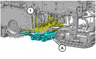
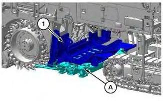
4. Use Tooling (A) to support the weight of anti-slab (1). The weight of anti-slab (1) is approximately 350 kg (772 lb)
Illustration 2
5. Remove two bolts (2). Remove plate (3).
3
6. Remove twelve bolts (4).
Illustration
g06134639
g06134676
Illustration
g06134680
Illustration 4
g06134681
7. Install Tooling (B) as shown. Use tooling (B) to remove flange (5).
Illustration 5
g06134666
8. Remove twelve bolts (6). Open rotor chamber access door (7).
Illustration 6
g06134696
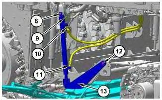
9. Disconnect hose assembly (10) and hose assembly (11). Disconnect harness assembly (9). Remove retaining pin (8) and bolt (12). Remove averaging arm (13). Repeat process for opposite side of the anti-slab.
Illustration 7
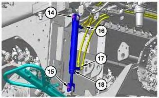
10. Disconnect hose assemblies (16) and hose assemblies (17). Remove retaining pin (14) and retaining pin (15). Remove hydraulic cylinder (18). Repeat process for opposite side of antislab.
Illustration 8
11. Use Tooling (A) to remove anti-slab (1).
g06134747
Installation Procedure
1. Install anti-slab (1) in the reverse order of removal.
Copyright 1993 - 2025 Caterpillar Inc. All Rights Reserved. Private Network For SIS Licensees. Tue Mar 11 10:43:42 UTC+0700 2025
g06134731
Product: COLD PLANER
Model: PM820 COLD PLANER TLZ
Configuration: PM820 Cold Planer TLZ00001-UP (MACHINE) POWERED BY C18 Engine
Disassembly and Assembly
PM820, PM822, and PM825 Cold Planer Machine Systems
Media Number -M0082957-05 Publication Date -01/12/2019 Date Updated -03/12/2019
Belt Guard (Rotor Drive) - Remove and Install
SMCS - 7174-010
Removal Procedure Table 1 Required Tools Tool Part Number Part Description Qty A 439-3938 Link Bracket 1 B 418-4568 Table As 1
Start By:
a. Remove the belt tensioner.
b. Remove the rotor drive belts.
i07140230
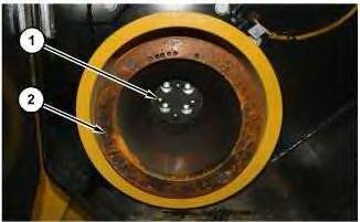
1. Remove four bolts (1) and remove pulley (2).
Illustration 2
2. Remove bolts (3) and remove pulley (4).
g06233847
Illustration 3
g06233853
3. Remove cable straps (6). Disconnect harness assembly (5) and position out of the way.
Illustration 4
g06233932
4. Remove bolt (7) and remove plate assembly (8).
Illustration 5
g06233947
5. Remove bolts (10), plates (11), and gasket (12).
6. Remove four bolts (9) and the four spacers on the backside of the guard.
Illustration 6
g06233956
7. Install Tooling (A) and attach suitable lifting device to belt guard (15). The weight of belt guard (15) is approximately 127 kg (280 lb).
8. Position Tooling (B) beneath belt guard (15).
9. Remove three bolts (13) and two bolts (14). Remove belt guard (15).
Installation Procedure
1. Install belt guard (15) in the reverse order of removal.
Copyright 1993 - 2025 Caterpillar Inc. All Rights Reserved. Private Network For SIS Licensees. Tue Mar 11 10:35:15 UTC+0700 2025
Product: COLD PLANER
Model: PM820 COLD PLANER TLZ
Configuration: PM820 Cold Planer TLZ00001-UP (MACHINE) POWERED BY C18 Engine
Disassembly and Assembly
PM820, PM822, and PM825 Cold Planer Machine Systems
Media Number -M0082957-05
Publication Date -01/12/2019
Date Updated -03/12/2019
Blower Fan - Remove and Install - Conveyor Fumes Extractor
SMCS - 1356-010; 7301; 7311-010
Removal Procedure
Personal injury can result from hydraulic oil pressure and hot oil.
Hydraulic oil pressure can remain in the hydraulic system after the engine has been stopped. Serious injury can be caused if this pressure is not released before any service is done on the hydraulic system.
Make sure all of the attachments have been lowered, oil is cool before removing any components or lines.
NOTICE
Care must be taken to ensure that fluids are contained during performance of inspection, maintenance, testing, adjusting, and repair of the machine. Be prepared to collect the fluid with suitable containers before opening any compartment or disassembling any component containing fluids.
Refer to Special Publication, NENG2500, "Caterpillar Tools and Shop Products Guide"for tools and supplies to collect and contain fluids in Caterpillar machines.
i06790508
Dispose of all fluids according to local regulations.
Note: Put identification marks on all lines, on all hoses, on all wires, and on all tubes for installation purposes. Plug all lines, hoses, and tubes to help prevent fluid loss and keep contaminants from entering the system.
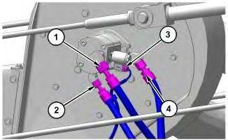
1. Disconnect hose assembly (1), hose assembly (2), and hose assembly (4). Disconnect harness assembly (3).
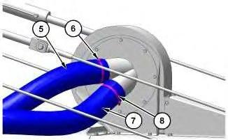
2. Remove hose clamp (6) and hose clamp (8). Remove hose (5) and hose (7).
Illustration 1
g06116315
Illustration 2
g06116318
Illustration 3
g06116323
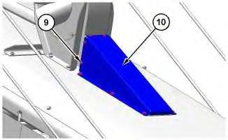
3. Remove twelve bolts (9). Remove bent plate (10).
Illustration 4
g06116327
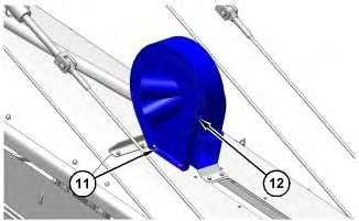
4. Remove four bolts (11). With the assistance of another person remove conveyor fumes extractor blower fan (12). The weight of conveyor fumes extractor blower fan (12) is approximately 38 kg (85 lb).
Installation Procedure
1. Install conveyor fumes extractor blower fan (12) in the reverse order of removal.
Copyright 1993 - 2025 Caterpillar Inc. All Rights Reserved. Private Network For SIS Licensees. Tue Mar 11 11:20:12 UTC+0700 2025
Product: COLD PLANER
Model: PM820 COLD PLANER TLZ
Configuration: PM820 Cold Planer TLZ00001-UP (MACHINE) POWERED BY C18 Engine
Disassembly and Assembly
PM820, PM822, and PM825 Cold Planer Machine Systems
Media Number -M0082957-05
Publication Date -01/12/2019
Date Updated -03/12/2019
Control Manifold - Remove and Install - Auxiliary Power Unit
SMCS - 3073-010; 3206-010; 3206-010-AOC; 5137-010-AOC; 5264-010
Removal Procedure
1
i06759042
Illustration
g06109506
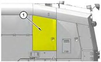
1. Open access door (1).
Illustration 2
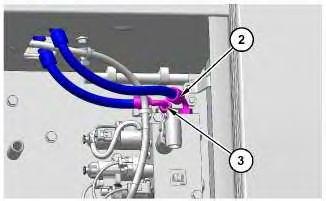
2. Disconnect hose assembly (2) and hose assembly (3).
Illustration 3
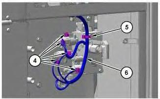
3. Disconnect harness assemblies (4). Remove cable strap (5). Place harness assembly (6) out of the way.
Illustration 4
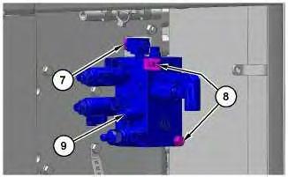
4. Remove two bolts (8). While removing auxiliary power unit control manifold (9), disconnect hose assembly (7) once hose assembly (7) is pulled through the access panel.
g06109522
g06109539
g06109559
Installation Procedure
1. Install auxiliary power unit control manifold (9) in the reverse order of removal.
Copyright 1993 - 2025 Caterpillar Inc. All Rights Reserved. Private Network For SIS Licensees.
Tue Mar 11 11:18:41 UTC+0700 2025
Product: COLD PLANER
Model: PM820 COLD PLANER TLZ
Configuration: PM820 Cold Planer TLZ00001-UP (MACHINE) POWERED BY C18 Engine
Disassembly and Assembly
PM820, PM822, and PM825 Cold Planer Machine Systems
Media Number -M0082957-05
Publication Date -01/12/2019
Date Updated -03/12/2019
Control Manifold - Remove and Install - Conveyor
SMCS - 3073-010; 3206-010; 3206-010-AOC; 5137-010-AOC; 5264-010
Removal Procedure
Personal injury can result from hydraulic oil pressure and hot oil.
Hydraulic oil pressure can remain in the hydraulic system after the engine has been stopped. Serious injury can be caused if this pressure is not released before any service is done on the hydraulic system.
Make sure all of the attachments have been lowered, oil is cool before removing any components or lines.
NOTICE
Care must be taken to ensure that fluids are contained during performance of inspection, maintenance, testing, adjusting, and repair of the machine. Be prepared to collect the fluid with suitable containers before opening any compartment or disassembling any component containing fluids.
Refer to Special Publication, NENG2500, "Caterpillar Tools and Shop Products Guide"for tools and supplies to collect and contain fluids in Caterpillar machines.
Dispose of all fluids according to local regulations.
i06781873
Note: Put identification marks on all lines, on all hoses, on all wires, and on all tubes for installation purposes. Plug all lines, hoses, and tubes to help prevent fluid loss and keep contaminants from entering the system.
Illustration 1
g06112529
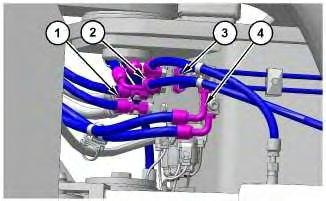
1. Disconnect two hose assemblies (1), four hose assemblies (2), two hose assemblies (3), and two hose assemblies (4).
Illustration 2
g06112543
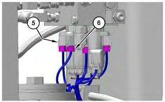
2. Disconnect harness assembly (5). Disconnect four harness assemblies (6).
Illustration 3 g06112548
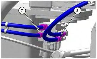
3. Disconnect two hose assemblies (7) and two hose assemblies (8).
Illustration 4
g06112565
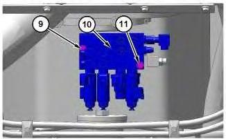
4. Remove bolt (9) and bolt (11). Remove conveyor control manifold (10).
Installation Procedure
1. Install conveyor control manifold (10) in the reverse order of removal.
Copyright 1993 - 2025 Caterpillar Inc. All Rights Reserved. Private Network For SIS Licensees. Tue Mar 11 11:19:14 UTC+0700 2025
Product: COLD PLANER
Model: PM820 COLD PLANER TLZ
Configuration: PM820 Cold Planer TLZ00001-UP (MACHINE) POWERED BY C18 Engine
Disassembly and Assembly
PM820, PM822, and PM825 Cold Planer Machine Systems
Media Number -M0082957-05
Publication Date -01/12/2019
Date Updated -03/12/2019
Control Manifold - Remove and Install - Cutter Box
SMCS - 3073-010; 3206-010; 3206-010-AOC; 5137-010-AOC; 5264-010
Removal Procedure
Personal injury can result from hydraulic oil pressure and hot oil.
Hydraulic oil pressure can remain in the hydraulic system after the engine has been stopped. Serious injury can be caused if this pressure is not released before any service is done on the hydraulic system.
Make sure all of the attachments have been lowered, oil is cool before removing any components or lines.
NOTICE
Care must be taken to ensure that fluids are contained during performance of inspection, maintenance, testing, adjusting, and repair of the machine. Be prepared to collect the fluid with suitable containers before opening any compartment or disassembling any component containing fluids.
Refer to Special Publication, NENG2500, "Caterpillar Tools and Shop Products Guide"for tools and supplies to collect and contain fluids in Caterpillar machines.
Dispose of all fluids according to local regulations.
i06782523
Note: Put identification marks on all lines, on all hoses, on all wires, and on all tubes for installation purposes. Plug all lines, hoses, and tubes to help prevent fluid loss and keep contaminants from entering the system.
1. Raise the machine to Service Height. Refer to Operation & Maintenance Manual, "Operator Controls" , All Leg Raise/Lower and Auto Leveling.
2. Install the rear service leg locks. Use suitable cribbing to support the front of the machine.
1
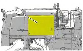
3. Open engine bay access door (1).
2
Note: Some items have been removed for photo clarity.
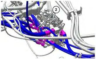
4. Disconnect fifteen hose assemblies (2).
Illustration
g06113061
Illustration
g06113068