


Product: COLD PLANER
Model: PM-565B COLD PLANER 8GS
Configuration: PM-565B Cold Planer 8GS00001-UP (MACHINE) POWERED BY 3408C Engine
Disassembly and Assembly
3408E ENGINE SUPPLEMENT FOR PM-565 & PM-565B COLD PLANER
Media Number -KENR3022-00
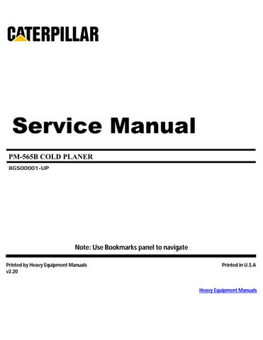
Air Cleaner
SMCS - 1051-010
Publication Date -01/03/1998 Date Updated -10/10/2001
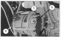
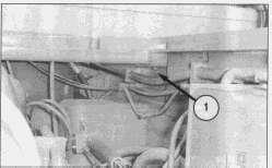
Remove & Install Air Cleaner
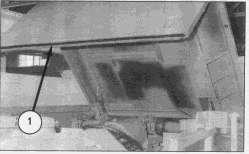
1. Raise the powered hood assembly.
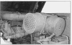
2. Loosen hose clamp (1).
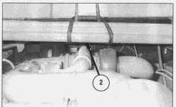
3. Disconnect hose (2) from the air cleaner assembly.
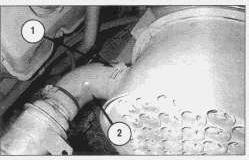
4. Loosen hose clamp (3).
5. Disconnect hose (4).
6. Attach a strap to the air cleaner assembly.
7. Remove four bolts (5) and washers.
9. Remove air cleaner assembly. The weight of the air cleaner assembly is 27 kg (60 lb).
NOTE: For installation of the air cleaner assembly, reverse the removal steps.
Copyright 1993 - 2024 Caterpillar Inc. All Rights Reserved. Private Network For SIS Licensees.
This is the sample of the manual click on the download link for complete manual
DOWNLOAD LINK
For some reason if link does not work download this pdf and then click
Product: COLD PLANER
Model: PM-565B COLD PLANER 8GS
Configuration: PM-565B Cold Planer 8GS00001-UP (MACHINE) POWERED BY 3408C Engine
Disassembly and Assembly
3408E ENGINE SUPPLEMENT FOR PM-565 & PM-565B COLD PLANER
Media Number -KENR3022-00
Alternator V-Belt
SMCS - 1405-010
Publication Date -01/03/1998 Date Updated -10/10/2001
Remove & Install Alternator V-Belt
1. Raise the powered hood assembly.
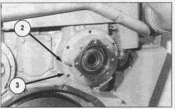
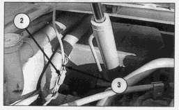
2. Loosen nut (1) on the tension rod.
3. Push alternator (2) towards the engine.
4. Remove alternator V-belt (3).
NOTE: For installation of the alternator V-belt, reverse the removal steps.
NOTE: Refer to Operation & Maintenance Manual KEBU6680 for information on alternator belt tensioning.
Copyright 1993 - 2024 Caterpillar Inc. All Rights Reserved. Private Network For SIS Licensees. Fri Sep 20 09:48:29 UTC+0530 2024
Product: COLD PLANER
Model: PM-565B COLD PLANER 8GS
Configuration: PM-565B Cold Planer 8GS00001-UP (MACHINE) POWERED BY 3408C Engine
Disassembly and Assembly
3408E ENGINE SUPPLEMENT FOR PM-565 & PM-565B COLD PLANER
Media Number -KENR3022-00
Alternator
SMCS - 1405-010
Publication Date -01/03/1998
Remove & Install Alternator
1. Raise the powered hood assembly.
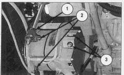
2. Disconnect two wire assemblies (3).
3. Loosen nut (1).

Date Updated -10/10/2001
4. Loosen three bolts and nuts (2). The third bolt and nut (2) is not shown and holds the alternator (6) to a bracket.
5. Reposition alternator V-belt (4).
6. Remove ground strap (5).
7. Remove three bolts and nuts (2).
7. Remove alternator (6).
NOTE: For installation of the alternator, reverse the removal steps.
8. Adjust the alternator V-belt to the correct tension. Refer to the Operation & Maintenance Manual KEBU6680 for the correct V-belt tension.
Copyright 1993 - 2024 Caterpillar Inc. All Rights Reserved. Private Network For SIS Licensees. Fri Sep 20 09:48:14 UTC+0530 2024
Product: COLD PLANER
Model: PM-565B COLD PLANER 8GS
Configuration: PM-565B Cold Planer 8GS00001-UP (MACHINE) POWERED BY 3408C Engine
Disassembly and Assembly
3408E ENGINE SUPPLEMENT FOR PM-565 & PM-565B COLD PLANER
Media Number -KENR3022-00
Batteries
SMCS - 1401-010
Publication Date -01/03/1998
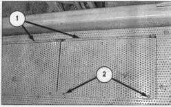
Remove & Install Batteries
Date Updated -10/10/2001
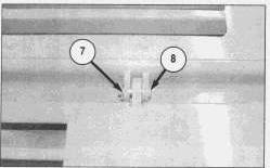
1. Remove two screws (2). Two screws (2) are located on each hinged cover plate (1).
2. Open hinged cover plate (1).
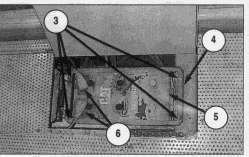
3. Disconnect battery cables (6).
4. Remove four nuts (3) and washers.
5. Remove two hold down brackets (4).
6. Use a suitable lifting device to remove battery (5). Remove the second battery in the same manner. The weight of each battery is 56 kg (125 lb).
NOTE: For installation of the batteries, reverse the removal steps.
Copyright 1993 - 2024 Caterpillar Inc.
Product: COLD PLANER
Model: PM-565B COLD PLANER 8GS
Configuration: PM-565B Cold Planer 8GS00001-UP (MACHINE) POWERED BY 3408C Engine
Disassembly and Assembly
3408E ENGINE SUPPLEMENT FOR PM-565 & PM-565B COLD PLANER
Media Number -KENR3022-00
Publication Date -01/03/1998 Date Updated -10/10/2001
Engine Support (Front)
SMCS - 1154-010
Remove & Install Engine Support (Front)
Start By:
a. remove powered hood assembly
b. remove air cleaner group
c. remove vibration damper
NOTE: Photos do not show the vibration damper removed.
1. Remove engine bottom covers to access support hardware.
2. Attach a suitable lifting device to front and rear lifting group to support the engine. The weight of the engine is 2300 kg (5100 lb).
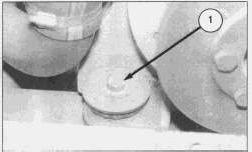
3. Remove right front mounting bolt (1).
4. Remove washer, large washer, rubber mount from bottom of engine frame.
5. Remove left front mounting bolt (not shown).
6. Remove washer, large washer, rubber mount from bottom of engine frame.
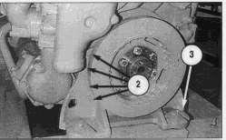
The engine is shown removed for photographic purposes.
7. Remove four bolts and washers (2) from each side of the engine.
8. Remove front engine support (3).
NOTE: The water spray bracket may interfere with the engine support removal, if necessary loosen bolts to position brackets for clearance.
NOTE: For installation of the engine support (front), reverse the removal steps.
End By:
a. install air cleaner group
b. install vibration damper
c. install powered hood assembly
Copyright 1993 - 2024 Caterpillar Inc. All Rights Reserved. Private Network For SIS Licensees. Fri Sep 20 09:49:14 UTC+0530 2024
Product: COLD PLANER
Model: PM-565B COLD PLANER 8GS
Configuration: PM-565B Cold Planer 8GS00001-UP (MACHINE) POWERED BY 3408C Engine
Disassembly and Assembly
3408E ENGINE SUPPLEMENT FOR PM-565 & PM-565B COLD PLANER
Media Number -KENR3022-00
Publication Date -01/03/1998 Date Updated -10/10/2001
Engine Supports (Rear)
SMCS - 1154-010
Remove & Install Engine Supports (Rear)
Start By:
a. remove powered hood assembly
b. remove air cleaner group
c. remove muffler assembly
1. Remove engine bottom covers to access support hardware.
2. Attach a suitable lifting device to front and rear lifting group to support the engine. The weight of the engine is 2300 kg (5100 lb).
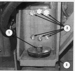
3. Remove right rear mounting bolt (1).
4. Remove washer, large washer, rubber mount from bottom of engine frame.
5. Remove left rear mounting bolt (similar to 1).
6. Remove washer, large washer, rubber mount from bottom of engine frame.
The right rear engine support (3) is integral with the muffler mount. Use extreme caution when removing the bolts (2) and the right rear engine support (3). The support (3) may move suddenly causing personal injury or death.
7. Remove six bolts (2) and washers from the engine supports (3) on each side of the engine.
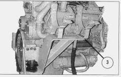
8. Remove right rear engine support (3) and left rear engine support (not shown).
NOTE: For installation of the engine supports (rear), reverse the removal steps.
End By:
a. install air cleaner group
b. install muffler assembly
c. install powered hood assembly
Product: COLD PLANER
Model: PM-565B COLD PLANER 8GS
Configuration: PM-565B Cold Planer 8GS00001-UP (MACHINE) POWERED BY 3408C Engine
Disassembly and Assembly
3408E ENGINE SUPPLEMENT FOR PM-565 & PM-565B COLD PLANER
Media Number -KENR3022-00
Engine
SMCS - 5602-010
Publication Date -01/03/1998
Date Updated -10/10/2001
Remove & Install Engine And Rotor Clutch
Start By:
a. remove propel pump, auxiliary pump, clutch pump and fan and conveyor pump
b. drain the coolant from the radiator into a suitable container
c. remove plates beneath and beside the engine compartment for access
d. remove the air cleaner assembly
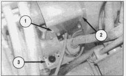
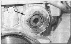
1. Remove eight bolts (1) and washers.
2. Remove cover (2).
NOTE: It is not necessary to remove rotor clutch filler (3).
3. Remove two hose assemblies (4). Cap or plug immediately.
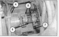
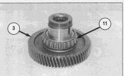
4. Remove eight bolts (5). Remove universal joint (6).
5. Remove bracket (7).
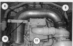
5. Loosen hose clamp (9), disconnect elbow (8) from turbocharger (11).
6. Remove two nuts and u-clamp (10).
7. Remove elbow (8).
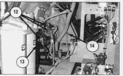
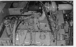
8. Disconnect six wire assemblies (12) from starter (13). Mark and identify wires for reinstallation.
9. Cut tie wrap and remove wire (14). Trace the wiring to the engine to be sure all tie wraps are cut.
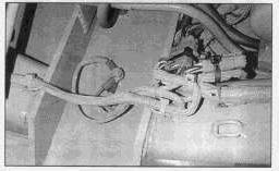
10. Cut tie wraps and disconnect electrical connections leading to the engine. Trace the wiring to the engine to be sure all tie wraps are cut. Mark and identify wires to aid in reinstallation.
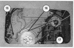
11. Remove coolant hose from water pump (15) (shown removed). Remove coolant temperature wire from the water pump (15) (not visible).
12. Disconnect two alternator wire assemblies (16).
13. Disconnect engine ground wire (17).
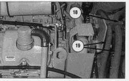
14. Remove bolts and clamp (18).
15. Reposition two hoses (19) to clear the engine and clutch assembly.
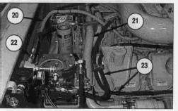
16. Cut tie wraps and disconnect wire (20).
17. Remove bracket and tube assembly (21).
18. Disconnect three hose assemblies (22) and (23). Cap or plug immediately.
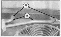
19. Loosen two clamps (24). Disconnect two radiator tubes (25).
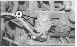
20. Disconnect two fuel lines (26). Cap or plug immediately to prevent spillage or line contamination.
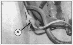
21. Disconnect electrical connection (27).
NOTE: The photo is taken from the underside of the engine compartment.
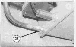
22. Remove hose (28). Cap or plug immediately.
NOTE: The photo is taken from the underside of the engine compartment.
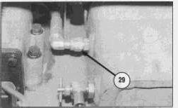
23. Remove hose (29). Cap or plug immediately.
NOTE: The photo is taken from the underside of the engine compartment.
24. Attach the engine lift brackets to a suitable hoist with a chain. The weight of the engine is 2300 kg (5100 lb).
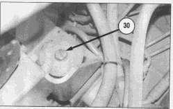
25. Remove one engine mount bolt and washer (30) from each of four corners of the engine.
26. Thoroughly inspect the engine area for any wires or hoses which will interfere with engine removal.
27. Carefully lift the engine straight up (approximately 3 to 4 inches), making sure all the wires, hoses and connections are disconnected and are out of the way.
28. Slowly lift the engine up and out of the engine compartment. the weight of the engine is 2300 kg (5100 lb).
29. Move the engine to a safe working area.
NOTE: For installation of the engine, reverse the removal steps.
End By:
a. install propel pump, auxiliary pump and clutch pump
b. install conveyor and fan drive pump
c. install the air cleaner
d. replace removed engine compartment plates
Copyright 1993 - 2024 Caterpillar Inc. All Rights Reserved.
Private Network For SIS Licensees.
Fri Sep 20 09:48:58 UTC+0530 2024
Product: COLD PLANER
Model: PM-565B COLD PLANER 8GS
Configuration: PM-565B Cold Planer 8GS00001-UP (MACHINE) POWERED BY 3408C Engine
Disassembly and Assembly
3408E ENGINE SUPPLEMENT FOR PM-565 & PM-565B COLD PLANER
Media Number -KENR3022-00 Publication Date -01/03/1998 Date Updated -10/10/2001
Gear Drive
SMCS - 1206-017; 1206-010
Remove & Install Gear Drive (Propel Pump or Auxiliary Pump)
Start By:
a. remove applicable pumps as described in KENR3025
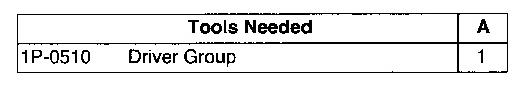
1. Remove six bolts (1).
2. Install two forcing screws (2) as shown.
3. Remove gear drive (propel pump) (3) and the O-ring. Use two people, the weight of the gear drive is 27 kg (60 lb).
NOTE: For installation of the gear drive, reverse the removal steps.
End By:
a. install pumps
Disassemble & Assemble Gear Drive (Auxiliary Pump)
Start By:
a. remove gear drive (auxiliary pump)
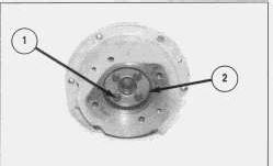
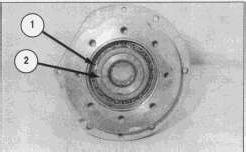
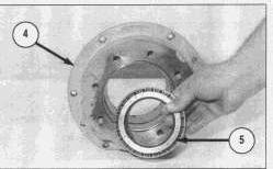
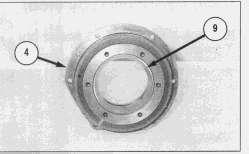
1. Remove four bolts (1) and washers.
2. Remove plate (2).
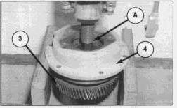
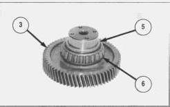
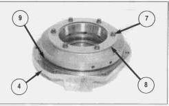
5. Remove six bolts (7), washers and plate (8) from housing (4).
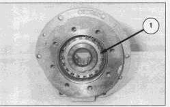
6. Remove O-ring seal (9). Check for wear or damage. Replace if necessary.
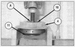
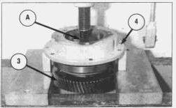
7. Use Tool (A) and a press to remove bearing race (11) and bearing (10) (not shown) from housing (4).
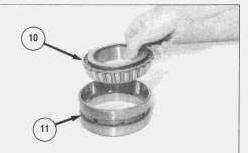
8. Remove bearing (10) from race (11).
NOTE: For assembly of the gear drive (auxiliary), reverse the disassembly steps.
End By:
a. install gear drive (auxiliary pump)
Disassemble & Assemble Gear Drive (Propel Pump)
Start By:
remove gear drive (propel pump)
1.
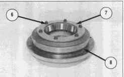
6. Remove six bolts (6), washers and plate (7).
7. Remove O-ring seal (8). Check for wear or damage. Replace if necessary.
8. If necessary, remove bearing race (9) from housing (4).
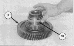
9. Remove spacer (10) from gear shaft assembly (3).
10. If necessary, remove bearing (11) from gear shaft assembly (3).
NOTE: For assembly of the gear drive (propel pump), reverse the disassembly steps.
End By:
a. install gear drive (propel pump)
Product: COLD PLANER
Model: PM-565B COLD PLANER 8GS
Configuration: PM-565B Cold Planer 8GS00001-UP (MACHINE) POWERED BY 3408C Engine
Disassembly and Assembly
3408E ENGINE SUPPLEMENT FOR PM-565 & PM-565B COLD PLANER
Media Number -KENR3022-00 Publication Date -01/03/1998 Date Updated -10/10/2001
Hood Assembly (Powered)
SMCS - 7263-010
Remove & Install Hood Assembly (Powered)
1. Raise powered hood assembly (1).
2. Support the hood assembly with straps and a suitable lifting device.
3. Disconnect electrical connection (2). Cut tie-wrap (3).

4. Remove cotter pin (4) and pin (5). Repeat on the other side.
5. Lower cylinder assembly (6) out of the way. Repeat on the other side.
6. Lower the hood assembly to the closed position.
7. Remove cotter pin (7) and pin (8). Repeat for the other side.
8. Reposition straps and add chains to lift from each corner of the hood (1).
9. Carefully lift the hood assembly up and away from the machine. The weight of the hood assembly is 248 kg (550 lb).
NOTE: For installation of the hood assembly (powered), reverse the removal steps. Copyright 1993 - 2024 Caterpillar Inc.
Rights Reserved.
Network For SIS Licensees. Fri Sep 20 09:49:59 UTC+0530 2024
Product: COLD PLANER
Model: PM-565B COLD PLANER 8GS
Configuration: PM-565B Cold Planer 8GS00001-UP (MACHINE) POWERED BY 3408C Engine
Disassembly and Assembly
3408E ENGINE SUPPLEMENT FOR PM-565 & PM-565B COLD PLANER
Media Number -KENR3022-00
Hood Support
SMCS - 7251-010
Publication Date -01/03/1998 Date Updated -10/10/2001
Remove & Install Hood Support
Start By:
a. remove powered hood assembly
1. Remove two bolts (1) and washers (both sides).
2. Attach a strap and suitable lifting device to hood support (2) as shown.
3. Remove the hood support. The weight of the hood support is 113 kg (250 lb).
NOTE: For installation of the hood support, reverse the removal steps.
End By:
a. install powered hood assembly
This is the sample of the manual click on the download link for complete manual
DOWNLOAD LINK
For some reason if link does not work download this pdf and then click