This is the sample of the manual click on the download link for complete manual
DOWNLOAD LINK
For some reason if link does not work download this pdf and then click

Product: CHALLENGER
Model: MT865 CHALLENGER BDS
Configuration: C-12, C-15, C-16 Caterpillar Engines For AGCO Challenger BDS00001-UP (MACHINE)
Disassembly and Assembly
C-15 and C-16 Industrial Engines
Media Number -RENR2346-01 Publication Date -01/09/2002 Date Updated -30/09/2002
Air Compressor - Remove and Install
SMCS - 1803-010
Removal Procedure
1
Tools
NOTICE
Keep all parts clean from contaminants.
Contamination of the hydraulic system with foreign material will reduce the service life of the hydraulic system components.
To prevent contaminants from entering the hydraulic system, always plug or cap the lines, fittings, or hoses as they are disconnected. Cover any disassembled components and clean them properly before assembly.
Clean the hydraulic system properly after any major component exchange or especially after a component failure, to remove any contamination.
NOTICE
Care must be taken to ensure that fluids are contained during performance of inspection, maintenance, testing, adjusting and repair of the product. Be prepared to collect the fluid with suitable containers before opening any compartment or disassembling any component containing fluids.
Refer to Special Publication, NENG2500, "Caterpillar Dealer Service Tool Catalog" for tools and supplies suitable to collect and contain fluids on Caterpillar products.
Dispose of all fluids according to local regulations and mandates.
Do not disconnect the air lines until the air pressure in the system is at zero. If hose is disconnected under pressure it can cause personal injury.
1. Drain the cooling system into a suitable container for storage or disposal. Refer to Disassembly and Assembly, "Cooling System Coolant - Change".
2. Loosen the purge valves, and release the air pressure in the air tank.
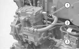
Illustration 1
Typical example
3. Disconnect coolant tube assembly (1) and air hose assembly (2) from the air compressor.
4. Disconnect oil tube assembly (3) from the air compressor.
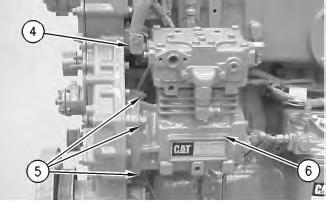
Illustration 2
Typical example
g00928842
5. Remove coolant hose assembly (4) from the air compressor.
6. Remove nuts (5) that hold the air compressor to the accessory drive.
7. Remove air compressor (6) from the engine.
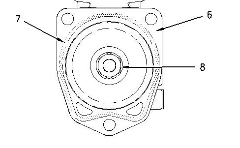
Illustration 3
Typical example
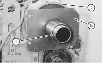
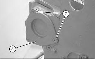
8. Remove O-ring seal (7) from the air compressor.
g00929487
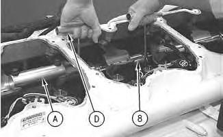
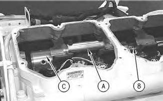
Note: Install Tooling (A) to the mounting flange of the air compressor. Tooling (A) will keep the drive gear stationary. The retaining nut for the drive gear can be removed.
9. Remove retaining nut (8) for the drive gear.
10. Remove the air compressor drive gear from the air compressor.
Installation Procedure
Table 2
Required Tools
Tool Part Number Part Description Qty
A 132-5451 Holding Fixture 1
NOTICE
Keep all parts clean from contaminants.
Contamination of the hydraulic system with foreign material will reduce the service life of the hydraulic system components.
To prevent contaminants from entering the hydraulic system, always plug or cap the lines, fittings, or hoses as they are disconnected. Cover any disassembled components and clean them properly before assembly.
Clean the hydraulic system properly after any major component exchange or especially after a component failure, to remove any contamination.
1. Install the air compressor drive gear onto the shaft of the air compressor.
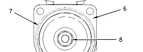

Illustration 4 g00929487
Typical example
Note: Install Tooling (A) to the mounting flange of the air compressor. Tooling (A) will keep the drive gear stationary. The retaining nut for the drive gear can be installed.
2. Install retaining nut (8) for the drive gear. For compressors that have a straight shaft, refer to Step 3 in order to tighten nut (8) . For compressors that have a tapered shaft, refer to Step 4 in order to tighten nut (8) .
3. Tighten retaining nut (8) to a torque of 460 ± 60 N·m (339 ± 44 lb ft).
4. Tighten nut (8) to a torque of 170 ± 15 N·m (125 ± 11 lb ft). Place a driver which is slightly larger than nut (8) over nut (8) and tap the driver with a hammer. Tighten nut (8) again to a torque of 170 ± 15 N·m (125 ± 11 lb ft).
5. Install new O-ring seal (7) on the air compressor.
6. Position air compressor (6) on the engine.
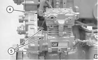
Illustration 5 g00620840
Typical example
7. Install nuts (5) in order to hold the air compressor on the engine.
8. Connect coolant tube assembly (4) to the air compressor.
Illustration 6
Typical example
g00620850
9. Connect coolant tube assembly (1) to the air compressor.
10. Connect air hose assembly (2) to the air compressor.
NOTICE
To prevent water from collecting and freezing in the air compressor lines, ensure that the air compressor lines are sloping downward and away from the air compressor.
11. Connect oil tube assembly (3) to the air compressor. Copyright 1993 - 2024 Caterpillar Inc.
Network For SIS Licensees. Mon Feb 19 23:38:38 UTC+0530 2024
Product: CHALLENGER
Model: MT865 CHALLENGER BDS
Configuration: C-12, C-15, C-16 Caterpillar Engines For AGCO Challenger BDS00001-UP (MACHINE)
Disassembly and Assembly
C-15 and C-16 Industrial Engines
Media Number -RENR2346-01
Publication Date -01/09/2002
Alternator - Remove and Install
SMCS - 1405-010
Removal Procedure NOTICE
Keep all parts clean from contaminants.
Date Updated -30/09/2002
Contaminants may cause rapid wear and shortened component life.
1. Turn the battery disconnect switch to the OFF position.
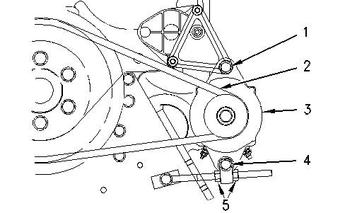
Illustration 1 g00596882
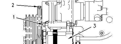
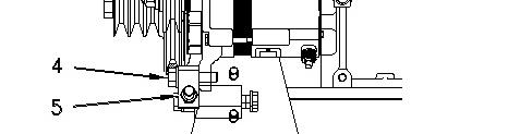
Illustration 2 g00596913
2. Put identification on the harness assemblies for installation purposes. Remove the harness assemblies from alternator (3).
3. Loosen nuts (5) on the adjustment rod.
4. Loosen the nut on bolt (1). Push the top of the alternator toward the cylinder block. Remove V-belt (2).
5. Remove bolts (1) and (4). Remove alternator (3).
Installation Procedure
NOTICE
Keep all parts clean from contaminants.
Contaminants may cause rapid wear and shortened component life.
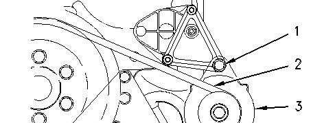
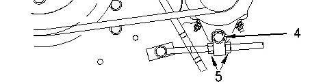
Illustration 3 g00596882
Illustration 4 g00596913
1. Put alternator (3) in position on the alternator bracket and install bolt (1).
2. Put the adjustment rod in position on the alternator and install bolt (4).
3. Install V-belt (2). Tighten the V-belt. Refer to Testing and Adjusting, "Belt Tension Chart".
4. Tighten nuts (5) to a torque of 30 ± 15 N·m (22 ± 11 lb ft).
5. Install the harness assemblies on the alternator.
6. Turn the battery disconnect switch to the ON position.
Product: CHALLENGER
Model: MT865 CHALLENGER BDS
Configuration: C-12, C-15, C-16 Caterpillar Engines For AGCO Challenger BDS00001-UP (MACHINE)
Disassembly and Assembly
C-15 and C-16 Industrial Engines
Media Number -RENR2346-01
Publication Date -01/09/2002
Date Updated -30/09/2002
Atmospheric Pressure Sensor - Remove and Install
SMCS - 1923-010
Removal Procedure NOTICE
Keep all parts clean from contaminants.
Contaminants may cause rapid wear and shortened component life.
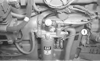
Illustration 1 g00621509 Typical example
1. Disconnect the harness assembly for atmospheric pressure sensor (1).
2. Remove atmospheric pressure sensor (1).