


Note: Use Bookmarks panel to navigate

Product: CHALLENGER
Model: MT755 CHALLENGER ALM
Configuration: C-9 Caterpillar Engine for AGCO Challenger ALM00001-UP (MACHINE)
Disassembly and Assembly
MT735, MT745, MT755 and MT765 Agricultural Tractors Engine Supplement
Media Number -RENR1870-00 Publication Date -01/04/2002 Date Updated -03/06/2002
Aftercooler - Remove and Install
SMCS - 1063-010
Removal Procedure
1. Raise the hood. Refer to Operation and Maintenance Manual, "Hood (Engine Compartment) - Raise/Lower".

This is the sample of the manual click on the download link for complete manual
DOWNLOAD LINK
For some reason if link does not work download this pdf and then click
Illustration 1 g00845394
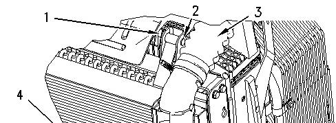
2. Loosen the clamp on hose (3). Remove the hose from the elbow of aftercooler (4). Repeat this Step for the hose and the clamp on the other side of the aftercooler.
3. Release latch assembly (5) on both sides of the aftercooler.
4. Remove clips (1) and pins (2) from the brace assemblies.
5. Remove aftercooler (4). The weight of the aftercooler is approximately 11 kg (25 lb).
Installation Procedure

2 g00845416
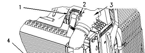
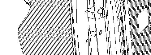

Illustration 3 g00845394
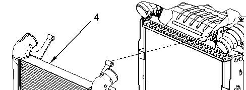
1. Place aftercooler (4) in position and install pins (2) and clips (1). The weight of the aftercooler is approximately 11 kg (25 lb).
2. Fasten latch assemblies (5) .
3. Slide hoses (3) on the elbows of aftercooler (4). Tighten the clamps on the hoses.
4. Lower the hood. Refer to Operation and Maintenance Manual, "Hood (Engine Compartment) - Raise/Lower".
Copyright 1993 - 2024 Caterpillar Inc. All Rights Reserved. Private Network For SIS Licensees. Thu Apr 11 14:07:02 UTC+0530 2024
Product: CHALLENGER
Model: MT755 CHALLENGER ALM
Configuration: C-9 Caterpillar Engine for AGCO Challenger ALM00001-UP (MACHINE)
Disassembly and Assembly
MT735, MT745, MT755 and MT765 Agricultural Tractors Engine Supplement
Media Number -RENR1870-00 Publication Date -01/04/2002 Date Updated -03/06/2002
Air Cleaner - Remove and Install
SMCS - 1051-010; 1054-010
Removal Procedure
Hot engine components can cause injury from burns. Before performing maintenance on the engine, allow the engine and the components to cool.
1. Open the hood. Refer to Operation and Maintenance Manual, "Hood (Engine Compartment) - Raise/Lower".
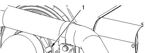
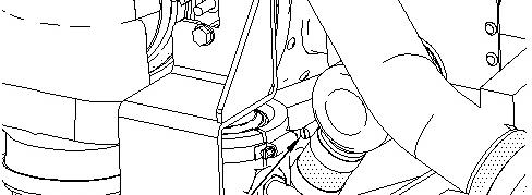

Illustration 1 g00846087
2. Loosen clamp (1) and remove clamp (1) from the turbocharger inlet and the air cleaner.
3. Loosen clamp (2) and slide the clamp down the hose.
The hose will be removed from the dust ejector when the air cleaner is removed from the machine.
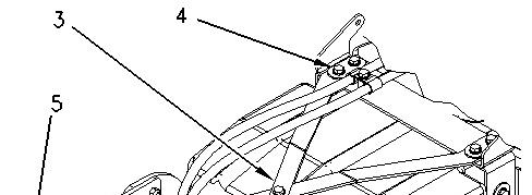
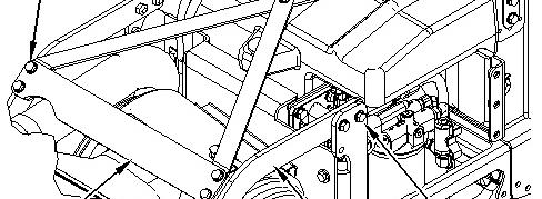

Illustration 2 g00846098
4. Remove bolts (5) on each side of plate (6). Remove plate (6) .
5. Remove bolts (4) on each side and remove brace assembly (3) .
6. Remove bolts (8) and support assembly (7) .
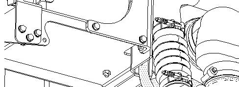
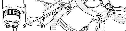
Illustration 3 g00846108
Note: The turbocharger was removed for illustrative purposes.
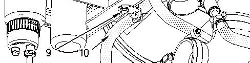
7. Remove bolt (9), the bracket, and hose assembly (10) from the support.
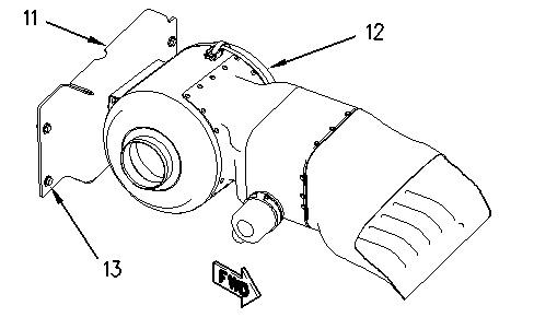
Illustration 4 g00846119
8. Remove bolts (13), support (11), and air cleaner (12) from the machine.
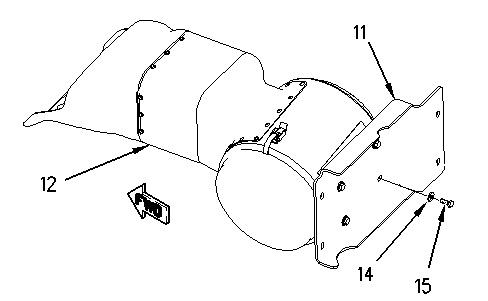
Illustration 5 g00846882
9. Remove bolts (15), washers (14), and support (11) from air cleaner (12) .
Installation Procedure
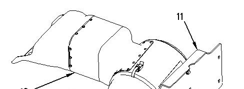

Illustration 6 g00846882
1. Install support (11) to air cleaner (12) with washers (14) and bolts (15) .
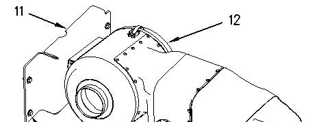
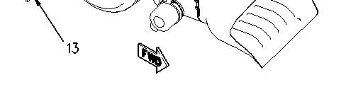
Illustration 7 g00846119
2. Place air cleaner (12) and support (11) in position on the machine. Place the hose to the ejector in position. Install bolts (13) .
3. Place clamp (2) in position and tighten the clamp.
4. Install clamp (1) to the turbocharger inlet and the air cleaner. Tighten the clamp.
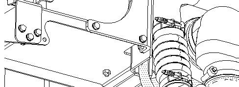
9 g00846108
5. Place hose assembly (10) and the bracket in position and install bolt (9) to the support.
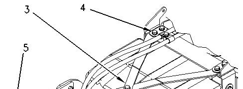
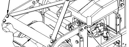

Illustration 10 g00846098
6. Install support assembly (7) with bolts (8) .
7. Place brace assembly (3) in position and install bolts (4) .
8. Place plate (6) in position and install bolts (5) on each side of the plate.
9. Close the hood. Refer to Operation and Maintenance Manual, "Hood (Engine Compartment) - Raise/Lower". Copyright 1993 - 2024 Caterpillar Inc. All Rights Reserved. Private Network For SIS Licensees. Thu Apr 11 14:06:44 UTC+0530 2024
Product: CHALLENGER
Model: MT755 CHALLENGER ALM
Configuration: C-9 Caterpillar Engine for AGCO Challenger ALM00001-UP (MACHINE)
Disassembly and Assembly
MT735, MT745, MT755 and MT765 Agricultural Tractors Engine Supplement
Media Number -RENR1870-00
Air Compressor - Remove and Install
SMCS - 1803-010
Removal Procedure NOTICE
Care must be taken to ensure that fluids are contained during performance of inspection, maintenance, testing, adjusting and repair of the product. Be prepared to collect the fluid with suitable containers before opening any compartment or disassembling any component containing fluids.
Refer to Special Publication, NENG2500, "Caterpillar Tools and Shop Products Guide" for tools and supplies suitable to collect and contain fluids on Caterpillar products.
Dispose of all fluids according to local regulations and mandates.
1. Raise the hood. Operation and Maintenance Manual, "Hood (Engine Compartment)Raise/Lower".
2. Remove the guard assembly on the left hand side. Operation and Maintenance Manual, "Guards - Remove and Install".
3. Drain the coolant from the cooling system into a suitable container for storage or disposal. The capacity of the cooling system is approximately 37 L (9.8 US gal). Refer to Operation and Maintenance Manual, "Cooling System Coolant (DEAC) - Change" or Operation and Maintenance Manual, "Cooling System Extended Life Coolant - Change" for your cooling system.
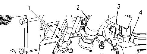
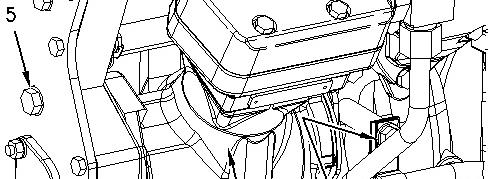


Illustration 1
4. Disconnect tube assemblies (1), (3), and (4) .
5. Remove bolt (8). Move the bracket and tube assembly (4) out of the way.
6. Loosen the clamp on hose (2) and remove the hose from the air compressor.
7. Disconnect hose assembly (6) .
8. Remove bolts (5). Remove air compressor (7). The weight of the air compressor is approximately 11 kg (25 lb).
Installation Procedure
Note: Check the O-ring seals for wear or for damage. Replace the O-ring seals, if necessary.
Illustration 2
g00844475
1. Place air compressor (7) in position and install bolts (5). The weight of the air compressor is approximately 11 kg (25 lb).
2. Connect hose assembly (6) .
3. Connect tube assemblies (3) and (1) to the air compressor.
4. Move tube assembly (4) and the bracket into position and install bolt (8) .
5. Connect tube assembly (4) .
6. Install hose (2) and tighten the clamp.
7. Fill the cooling system. The capacity of the cooling system is approximately 37 L (9.8 US gal). Refer to Operation and Maintenance Manual, "Cooling System Coolant (DEAC) -
Change" or Operation and Maintenance Manual, "Cooling System Extended Life CoolantChange" for your cooling system.
8. Install the guard assembly on the left hand side. Operation and Maintenance Manual, "Guards - Remove and Install".
9. Lower the hood. Operation and Maintenance Manual, "Hood (Engine Compartment)Raise/Lower". Copyright 1993 - 2024 Caterpillar Inc. All Rights Reserved.
Network For SIS Licensees. Thu Apr 11 14:13:51 UTC+0530 2024
Product: CHALLENGER
Model: MT755 CHALLENGER ALM
Configuration: C-9 Caterpillar Engine for AGCO Challenger ALM00001-UP (MACHINE)
Disassembly and Assembly
MT735, MT745, MT755 and MT765 Agricultural Tractors Engine Supplement
Media Number -RENR1870-00 Publication Date -01/04/2002 Date Updated -03/06/2002
Alternator - Remove and Install
SMCS - 1405-010
Removal Procedure
1. Remove the guard assembly on the right side of the radiator. Refer to Operation and Maintenance Manual, "Guards - Remove and Install".
2. Turn the disconnect switch to the Off position.
3. Remove the belt. Refer to Operation and Maintenance Manual, "Belt (Alternator and Water Pump) - Replace".
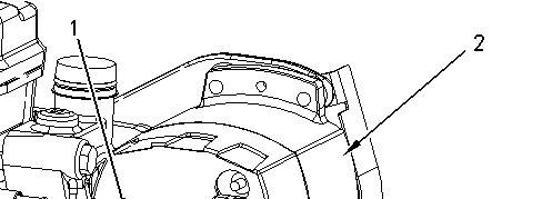
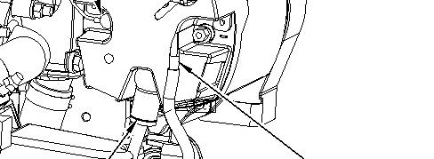

Illustration 1 g00839840
4. Remove wiring (1), (3), and (4) from alternator (2) .
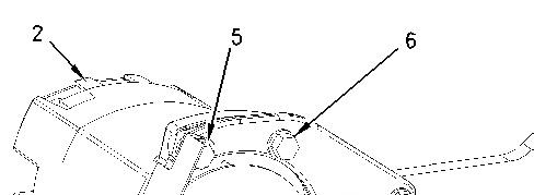
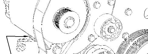

Illustration 2 g00839856
5. Remove bolts (5), (6), (7), and (8) .
6. Remove alternator (2) from the bracket.
Installation Procedure
Illustration 3 g00839856
1. Place alternator (2) in position on the bracket.
2. Install bolts (7), (8), (6), and (5) in order to hold the alternator in position.
Illustration 4
3. Install wiring (4), (3), and (1) to alternator (2) .
4. Install the belt. Refer to Operation and Maintenance Manual, "Belt (Alternator and Water Pump) - Replace".
5. Install the guard assembly on the right side of the radiator. Refer to Operation and Maintenance Manual, "Guards - Remove and Install".
6. Turn the disconnect switch to the On position. Copyright 1993 - 2024 Caterpillar Inc. All Rights Reserved. Private Network For SIS Licensees. Thu Apr 11 14:02:52 UTC+0530 2024
Product: CHALLENGER
Model: MT755 CHALLENGER ALM
Configuration: C-9 Caterpillar Engine for AGCO Challenger ALM00001-UP (MACHINE)
Disassembly and Assembly
MT735, MT745, MT755 and MT765 Agricultural Tractors Engine Supplement Media
Cooling Assembly - Install
SMCS - 1063-012; 1351-012; 1374-012; 1810-012
Installation Procedure Table 1
Required Tools
6V-9834
Note: Check the O-ring seals for wear or for damage. Replace the O-ring seals, if necessary.
NOTICE
Care must be taken to ensure that fluids are contained during performance of inspection, maintenance, testing, adjusting and repair of the product. Be prepared to collect the fluid with suitable containers before opening any compartment or disassembling any component containing fluids.
Refer to Special Publication, NENG2500, "Caterpillar Tools and Shop Products Guide" for tools and supplies suitable to collect and contain fluids on Caterpillar products.
Dispose of all fluids according to local regulations and mandates.
Personal injury can result from contact with refrigerant.
Contact with refrigerant can cause frost bite. Keep face and hands away to help prevent injury.
Protective goggles must always be worn when refrigerant lines are opened, even if the gauges indicate the system is empty of refrigerant.
Always use precaution when a fitting is removed. Slowly loosen the fitting. If the system is still under pressure, release it slowly in a well ventilated area.
Personal injury or death can result from inhaling refrigerant through a lit cigarette.
Inhaling air conditioner refrigerant gas through a lit cigarette or other smoking method or inhaling fumes released from a flame contacting air conditioner refrigerant gas, can cause bodily harm or death.
Do not smoke when servicing air conditioners or wherever refrigerant gas may be present.
Use a certified recovery and recycling cart to properly remove the refrigerant from the air conditioning system.
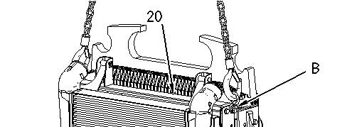
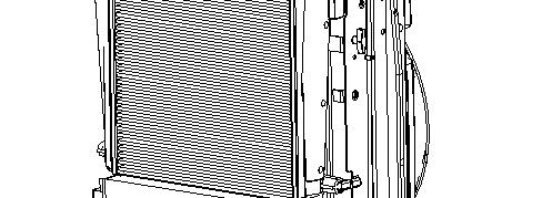
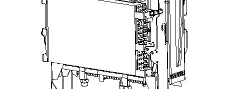

1
1. Attach Tooling (B) to cooling package (20). Use chains, a suitable lifting device, and Tooling (B) to place the cooling package in the original position. The weight of the cooling package is approximately 127 kg (280 lb).
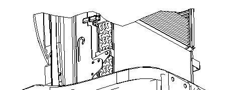
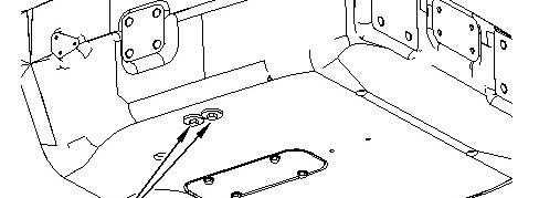

Illustration 2 g00854290
2. Install four bolts (21) .
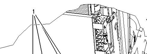
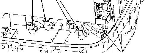

Illustration 3 g00854182
3. Connect hose assemblies (1) .
4. Connect hose assemblies (2) .
This is the sample of the manual click on the download link for complete manual
DOWNLOAD LINK
For some reason if link does not work download this pdf and then click