


Note: Use Bookmarks panel to navigate
This is the sample of the manual click on the download link for complete manual
DOWNLOAD LINK
For some reason if link does not work download this pdf and then click

Product: WHEELED EXCAVATOR
Model: M315D2 WHEELED EXCAVATOR CA4
Configuration: M315D2 Wheeled Excavator CA400001-UP (MACHINE) POWERED BY C4.4 Engine
Disassembly and Assembly
M315D, M315D Series 2, M315D2, M317D Series 2 and M317D2 Wheeled Excavators Machine Systems
Media Number -KENR6028-06
Publication Date -01/07/2015 Date Updated -18/10/2019
Accumulator (Brake) - Remove and Install
SMCS - 4263-010
Removal Procedure
Table 1
Required Tools
Tool Part Number Part Description Qty
6V-9509 Face Seal Plug 2
A
i01798264
6V-9830 Cap As 2
Start By:
a. Release the hydraulic pressure. Refer to Disassembly and Assembly, "Hydraulic System Pressure - Release".
Note: SERVICE DATA: TOOLING (A) WILL NOT BE IDENTIFIED IN PHOTOGRAPHS IN THE REMOVAL OR THE INSTALLATION. THIS TOOLING IS SHOWN IN ORDER TO ASSIST THE EXPERIENCED SERVICEMAN.
NOTICE
Care must be taken to ensure that fluids are contained during performance of inspection, maintenance, testing, adjusting, and repair of the product. Be prepared to collect the fluid with suitable containers before opening any compartment or disassembling any component containing fluids.
Refer to Special Publication, NENG2500, "Dealer Service Tool Catalog" for tools and supplies suitable to collect and contain fluids on Cat products.
Dispose of all fluids according to local regulations and mandates.
Personal injury can result from hydraulic oil pressure and hot oil.
Hydraulic oil pressure can remain in the hydraulic system after the engine has been stopped. Serious injury can be caused if this pressure is not released before any service is done on the hydraulic system.
Make sure all of the work tools have been lowered to the ground, and the oil is cool before removing any components or lines. Remove the oil filler cap only when the engine is stopped, and the filler cap is cool enough to touch with your bare hand.
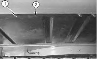
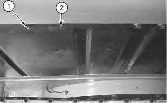
2. Remove panel (2).
2
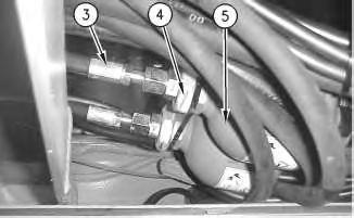
3. Disconnect hose assemblies (3).
4. Remove nuts (4).
5. Remove brake accumulators (5).
Installation Procedure
Illustration 3
1. Position brake accumulators (5).
2. Install nuts (4).
3. Connect hose assemblies (3).
g00920862
4
4. Position panel (2).
5. Install bolts (1).
Copyright 1993 - 2024 Caterpillar Inc. All Rights Reserved. Private Network For SIS Licensees. Tue Feb 20 01:41:49 UTC+0530 2024

Product: WHEELED EXCAVATOR
Model: M315D2 WHEELED EXCAVATOR CA4
Configuration: M315D2 Wheeled Excavator CA400001-UP (MACHINE) POWERED BY C4.4 Engine
Disassembly and Assembly
M315D, M315D Series 2, M315D2, M317D Series 2 and M317D2 Wheeled Excavators Machine Systems
Media Number -KENR6028-06
Publication Date -01/07/2015 Date Updated -18/10/2019
Actuator Motor (Air Distributor) - Remove and Install
SMCS - 7304-010-MQ; 7309-010-MQ; 7320-010-MQ
Removal Procedure
Start By:
i02872413
a. Remove the storage box and covers. Refer to Disassembly and Assembly, "Storage Box and Covers (Cab) - Remove and Install".
Note: Cleanliness is an important factor. Before the disassembly procedure, the exterior of the component should be thoroughly cleaned. This will help to prevent dirt from entering the internal mechanism.
1 g01207911
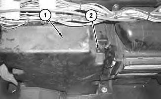
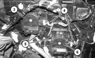
1. Remove screws (2) and cover (1).
2
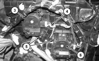
2. Disconnect harness assemblies (4).
3. Remove screws (5) and actuator motor (3).
4. Remove screws (5) and actuator motor (6).
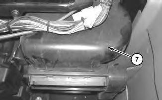
Illustration 3
5. Remove cover (7).
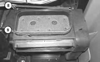
Illustration 4
g01207927
6. Remove screws (8). Repeat for the bottom.
7. Position filter cover assembly (9) forward.
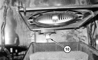
Illustration 5
8. Disconnect harness assembly (10).
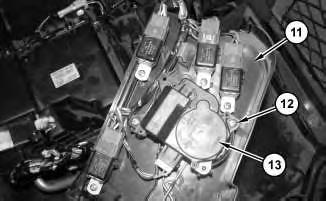
Illustration 6
g01208053
9. Reposition filter cover assembly (11) on the side, as shown.
10. Remove screws (12) and actuator motor (13).
Installation Procedure
Illustration 7
1. Position filter cover assembly (11) onto the side. Position actuator motor (13) and install screws (12).
Illustration 8
2. Connect harness assembly (10).
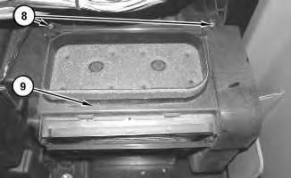
Illustration 9
3. Slide filter cover assembly (9) into position and install screws (8). Repeat for the bottom.
10
4. Install cover (7).
11
5. Position actuator motor (3) and install screws (5).
6. Position actuator motor (6) and install screws (5).
7. Connect harness assemblies (4).
Illustration 12
8. Position cover (1) and install screws (2).
g01207911
End By:
a. Install the storage box and covers. Refer to Disassembly and Assembly, "Storage Box and Covers (Cab) - Remove and Install".
Product: WHEELED EXCAVATOR
Model: M315D2 WHEELED EXCAVATOR CA4
Configuration: M315D2 Wheeled Excavator CA400001-UP (MACHINE) POWERED BY C4.4 Engine
Disassembly and Assembly
M315D, M315D Series 2, M315D2, M317D Series 2 and M317D2 Wheeled Excavators Machine Systems
Media Number -KENR6028-06
Publication Date -01/07/2015 Date Updated -18/10/2019
Blade - Remove and Install
SMCS - 6060-010
Removal Procedure
1. Lower the dozer blade to the ground.
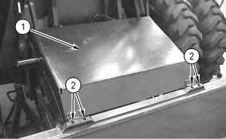
Illustration 1
i01832820
g00936274
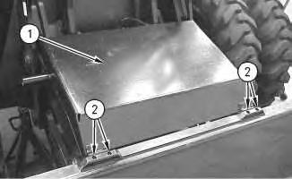
2. Remove bolts (2). Use two people and remove guard assembly (1) from the machine. The weight of guard assembly (1) is approximately 32 kg (70 lb).
2
3. Attach a suitable lifting device to the lower bracket assembly, as shown. Put slight lifting tension on the bracket assembly.
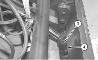
4. Remove bolt (3) from each pin assembly (4). Remove pin assemblies (4). Lower the lower bracket assembly to the ground.
3
5. Attach a suitable lifting device to the linkage assembly, as shown. Put slight lifting tension on the linkage assembly.
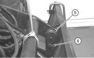
6. Remove bolt (6) from each pin assembly (5). Remove pin assemblies (5). Lower the linkage assembly.
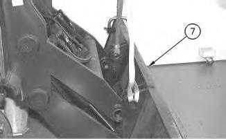
Illustration 4
g00936294
7. Attach a suitable lifting device to dozer blade (7) and remove dozer blade (7). The weight of dozer blade (7) is approximately 454 kg (1000 lb).
Installation Procedure
Table 1
Required Tools
Tool Part Number Part Description Qty
A 5P-0960 Molybdenum Grease 1
Note: Make sure that all of the bores and the pins are thoroughly clean prior to installation of the pins.
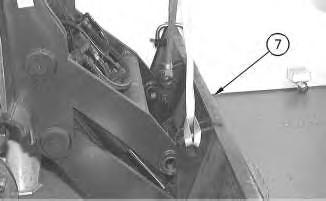
Illustration 5
g00936294
1. Attach a suitable lifting device to dozer blade (7) and install dozer blade (7). The weight of dozer blade (7) is approximately 454 kg (1000 lb).
Illustration 6 g00936291
2. Attach a suitable lifting device to the linkage assembly, as shown. Raise the linkage assembly. Apply Tooling (A) to pin assemblies (5) and to the pin bores. Install pin assemblies (5). Install bolt (6) into each pin assembly (5).
7
3. Attach a suitable lifting device to the lower bracket assembly, as shown. Raise the lower bracket assembly. Apply Tooling (A) to pin assemblies (4) and to the pin bores. Install pin assemblies (4). Install bolt (3) into each pin assembly (4).
8
4. Use two people and position guard assembly (1) onto the machine. The weight of guard assembly (1) is approximately 32 kg (70 lb). Install bolts (2).
Copyright 1993 - 2024 Caterpillar Inc.
Network For SIS Licensees. Tue Feb 20 00:48:45 UTC+0530 2024
Product: WHEELED EXCAVATOR
Model: M315D2 WHEELED EXCAVATOR CA4
Configuration: M315D2 Wheeled Excavator CA400001-UP (MACHINE) POWERED BY C4.4 Engine
Disassembly and Assembly
M315D, M315D Series 2, M315D2, M317D Series 2 and M317D2 Wheeled Excavators Machine Systems
Media Number -KENR6028-06
Publication Date -01/07/2015
Blade Cylinder - Remove and Install
SMCS - 7562-010-BG
Removal Procedure
Start By:
Date Updated -18/10/2019
i05761971
A. Release the hydraulic system pressure. Refer to Disassembly and Assembly, "Hydraulic System Pressure - Release".
Cylinders equipped with lock valves can remain pressurized for very long periods of time, even with the hoses removed.
Failure to relieve pressure before removing a lock valve or disassembling a cylinder can result in personal injury or death.
Ensure all pressure is relieved before removing a lock valve or disassembling a cylinder.
NOTICE
Care must be taken to ensure that fluids are contained during performance of inspection, maintenance, testing, adjusting, and repair of the product. Be prepared to collect the fluid with suitable containers before opening any compartment or disassembling any component containing fluids.
Refer to Special Publication, NENG2500, "Dealer Service Tool Catalog" for tools and supplies suitable to collect and contain fluids on Cat products.
Dispose of all fluids according to local regulations and mandates.
At operating temperature, the hydraulic oil is hot and under pressure. Hot oils can cause burns.
To prevent possible personal injury, release the pressure in the work tool hydraulic circuit (boom, stick, bucket, and swing), travel circuits, and the hydraulic oil tank at the filler cap before any hydraulic lines or components are disconnected or removed.
Remove the filler cap only when the engine is stopped and the filler cap is cool enough to touch.
NOTICE
Keep all parts clean from contaminants.
Contamination of the hydraulic system with foreign material will reduce the service life of the hydraulic system components.
To prevent contaminants from entering the hydraulic system, always plug or cap the lines, fittings, or hoses as they are disconnected. Cover any disassembled components and clean them properly before assembly.
Clean the hydraulic system properly after any major component exchange or especially after a component failure, to remove any contamination.
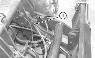
Illustration 1
1. Disconnect hose assemblies (1) .
g01262929
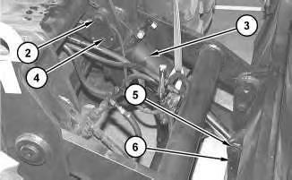
Illustration 2
g01262933
2. Attach a suitable lifting device to blade cylinder (3) . Put slight lifting tension on blade cylinder (3) .
3. Place suitable blocking under the lower linkage in order to support the lower linkage.
4. Remove bolt (2) and pin assembly (4) .
5. Remove bolt (5) and pin assembly (6) .
6. Remove blade cylinder (3) from the machine. The weight of blade cylinder (3) is approximately 48 kg (105 lb).
7. Repeat Step 1 through Step 6 for the other blade cylinder.
Disassembly and Assembly Information
Table 1
Required Tools
When you are using hydraulic cylinders and puller studs, always ensure that the rated capacity of the puller stud meets or exceeds the rated capacity of the hydraulic cylinder. If the puller stud does not meet or exceed the rated capacity of the hydraulic cylinder, a sudden failure of the puller stud could occur. The sudden failure of the puller stud could result in personal injury or death.
NOTICE
Do not use threaded rods that have not been hardened as tooling with hydraulic cylinders. The maximum rated tonnage should be stamped on one end of the puller studs. Do not use threaded rods that have not been stamped with the rated tonnage.
Cylinders equipped with lock valves can remain pressurized for very long periods of time, even with the hoses removed.
Failure to relieve pressure before removing a lock valve or disassembling a cylinder can result in personal injury or death.
Ensure all pressure is relieved before removing a lock valve or disassembling a cylinder.
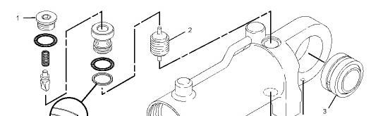
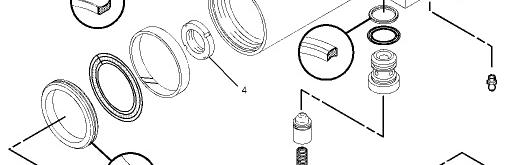
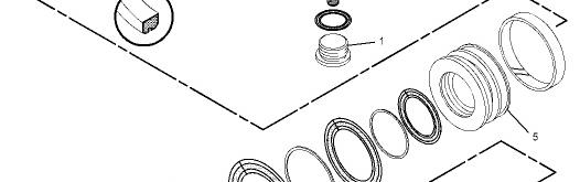
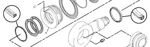
Note: Loosen plugs (1) to relieve any residual pressure in the cylinder.
Table 2
Cylinder Part Number Plugs (1) Nut (4) Head (6) Piston (5)
(1) Install plugs (1) . Refer to Table 2 for the correct torque.
(2) Install piston (2) with the orifice toward the ports for the hose.
(3) Use Tooling (E) to remove bearings (3) .
(4) Use Tooling (C) to install nut (4) . Refer to Table 2 for the correct torque.
(5) Install piston (5) . Refer to Table 2 for the correct torque.
(6) Install head (6) . Refer to Table 2 for the correct torque. Apply Tooling (F) to the pins for head (6) . Tighten the pins for head (6) to a torque of 8 N·m (70 lb in).
Installation Procedure
Illustration 4
1. Attach a suitable lifting device to blade cylinder (3) . Position blade cylinder (3) onto the machine. The weight of blade cylinder (3) is approximately 48 kg (105 lb).
2. Install pin assembly (6) and bolt (5) .
3. Install pin assembly (4) and bolt (2) .
Illustration 5
4. Connect hose assemblies (1) .
g01262929
5. Repeat Step 1 through Step 4 for the other blade cylinder.
6. Fill the hydraulic system with oil. Refer to Operation and Maintenance Manual, "Hydraulic System Oil - Change" for the proper procedure.
Copyright 1993 - 2024 Caterpillar Inc. All Rights Reserved. Private Network For SIS Licensees. Tue Feb 20 00:48:28 UTC+0530 2024
Product: WHEELED EXCAVATOR
Model: M315D2 WHEELED EXCAVATOR CA4
Configuration: M315D2 Wheeled Excavator CA400001-UP (MACHINE) POWERED BY C4.4 Engine
Disassembly and Assembly
M315D, M315D Series 2, M315D2, M317D Series 2 and M317D2 Wheeled Excavators Machine Systems Media Number -KENR6028-06
Blade Linkage - Remove and Install
SMCS - 6060-010
Removal Procedure
Table 1
Required Tools
Start By:
a. Remove the dozer blade. Refer to Disassembly and Assembly, "Blade - Remove and Install".
b. Release the hydraulic system pressure. Refer to Disassembly and Assembly, "Hydraulic System Presuure - Release".
Cylinders equipped with lock valves can remain pressurized for very long periods of time, even with the hoses removed.
Failure to relieve pressure before removing a lock valve or disassembling a cylinder can result in personal injury or death.
Ensure all pressure is relieved before removing a lock valve or disassembling a cylinder.
NOTICE
Care must be taken to ensure that fluids are contained during performance of inspection, maintenance, testing, adjusting, and repair of the product. Be prepared to collect the fluid with suitable containers before opening any compartment or disassembling any component containing fluids.
Refer to Special Publication, NENG2500, "Dealer Service Tool Catalog" for tools and supplies suitable to collect and contain fluids on Cat products.
Dispose of all fluids according to local regulations and mandates.
At operating temperature, the hydraulic oil is hot and under pressure. Hot oils can cause burns.
To prevent possible personal injury, release the pressure in the work tool hydraulic circuit (boom, stick, bucket, and swing), travel circuits, and the hydraulic oil tank at the filler cap before any hydraulic lines or components are disconnected or removed.
Remove the filler cap only when the engine is stopped and the filler cap is cool enough to touch.
This is the sample of the manual click on the download link for complete manual
DOWNLOAD LINK
For some reason if link does not work download this pdf and then click