

Note: Use Bookmarks panel to navigate
This is the sample of the manual click on the download link for complete manual

Note: Use Bookmarks panel to navigate
This is the sample of the manual click on the download link for complete manual
For some reason if link does not work download this pdf and then click

Product: WHEELED EXCAVATOR
Model: M313D WHEELED EXCAVATOR K3D
Configuration: M313D Excavator K3D00001-UP (MACHINE) POWERED BY C4.4 Engine
Disassembly and Assembly
M313D Wheeled Excavator Machine Systems
Media Number -KENR6025-04
SMCS - 4263-010
Removal Procedure Table 1
Required Tools Tool Part Number Part Description Qty A
6V-9509 Face Seal Plug 2
6V-9830 Cap As 2
Start By:
-06/03/2017
a. Release the hydraulic pressure. Refer to Disassembly and Assembly, "Hydraulic System Pressure - Release".
Note: SERVICE DATA: TOOLING (A) WILL NOT BE IDENTIFIED IN PHOTOGRAPHS IN THE REMOVAL OR THE INSTALLATION. THIS TOOLING IS SHOWN IN ORDER TO ASSIST THE EXPERIENCED SERVICEMAN.
Care must be taken to ensure that fluids are contained during performance of inspection, maintenance, testing, adjusting, and repair of the product. Be prepared to collect the fluid with suitable containers before opening any compartment or disassembling any component containing fluids.
Refer to Special Publication, NENG2500, "Dealer Service Tool Catalog" for tools and supplies suitable to collect and contain fluids on Cat products.
Dispose of all fluids according to local regulations and mandates.
Personal injury can result from hydraulic oil pressure and hot oil.
Hydraulic oil pressure can remain in the hydraulic system after the engine has been stopped. Serious injury can be caused if this pressure is not released before any service is done on the hydraulic system.
Make sure all of the work tools have been lowered to the ground, and the oil is cool before removing any components or lines. Remove the oil filler cap only when the engine is stopped, and the filler cap is cool enough to touch with your bare hand.
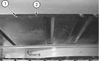
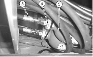
Illustration 2
3. Disconnect hose assemblies (3).
4. Remove nuts (4).
5. Remove brake accumulators (5).
Installation Procedure
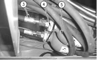
Illustration 3
1. Position brake accumulators (5).
2. Install nuts (4).
3. Connect hose assemblies (3).
g00920862
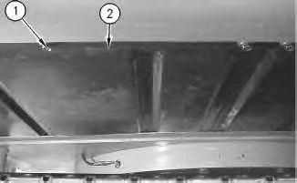
Illustration 4 g00920860
4. Position panel (2).
5. Install bolts (1). Mon Aug 19 02:23:48 UTC+0530 2024
Product: WHEELED EXCAVATOR
Model: M313D WHEELED EXCAVATOR K3D
Configuration: M313D Excavator K3D00001-UP (MACHINE) POWERED BY C4.4 Engine
Disassembly and Assembly
M313D Wheeled Excavator Machine Systems
Media Number -KENR6025-04
Publication Date -01/03/2017
SMCS - 4265-012
Installation Procedure
1 g01137373
Date Updated -06/03/2017
Illustration 2
2. Connect hose assemblies (6).
3
4
5
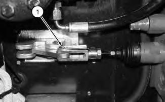
5. Install pin assembly (1).
6. Install the front cover underneath the cab.
Copyright 1993 - 2024 Caterpillar Inc. All Rights Reserved. Private Network For SIS Licensees. Mon Aug 19 02:23:26 UTC+0530 2024
Product: WHEELED EXCAVATOR
Model: M313D WHEELED EXCAVATOR K3D
Configuration: M313D Excavator K3D00001-UP (MACHINE) POWERED BY C4.4 Engine
Disassembly and Assembly
M313D Wheeled Excavator Machine Systems
Media Number -KENR6025-04
Publication Date -01/03/2017
SMCS - 4265-016
Assembly Procedure Table 1 Required Tools Tool Part Number Part Description Qty B 9S-3263 Thread Lock Compound 1 Illustration 1
Date Updated -06/03/2017
i02626437

Improper assembly of parts that are spring loaded can cause bodily injury.
To prevent possible injury, follow the established assembly procedure and wear protective equipment.
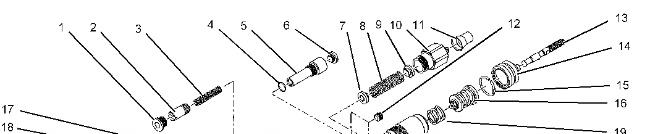
1. Install spring (3), spool (2), and plug (1). Tighten plug (1) to a torque of 75 N·m (55 lb ft).
2. Install O-ring seal (4), screw (5), and plug (6). Tighten screw (5) to a torque of 45 N·m (33 lb ft) Tighten plug (6) to a torque of 18 N·m (13 lb ft).
3. Install seat (7), spring (8), seat (9), plug assembly (10), and cap (11). Tighten plug assembly (10) to a torque of 45 N·m (33 lb ft).
4. Install plugs (12). Tighten plugs (12) to a torque of 3 N·m (26 lb in).
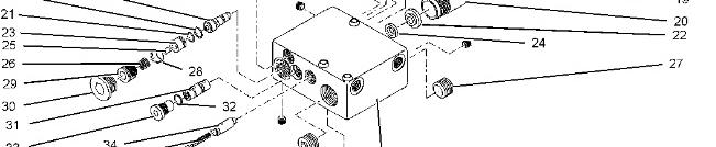
5. Apply Tooling (A) to pipe (20). Install seal (24), washer (22), and pipe (20). Tighten pipe (20) to a torque of 5 N·m (44 lb in). Install spring (19), spring assembly (16), retaining ring (15), boot (14), and lever (13).
6. Install plug (43). Tighten plug (43) to a torque of 45 N·m (33 lb ft). Install plug (27) to a torque of 45 N·m (33 lb ft).
7. Install sleeve (17), backup ring (18), seal (21), sleeve (23), spring (25), case (28), spring (26), and plug (29). Tighten plug (29) to a torque of 10 N·m (88 lb in). Install plug (30). Tighten plug (30) to a torque of 45 N·m (33 lb ft).
8. Install sleeve (31), O-ring seal (32), and plug (33). Tighten plug (33) to a torque of 75 N·m (55 lb ft).
9. Install sleeve (34), spring (35), pin (42), sleeve (41), spring (40), pin (39), O-ring seal (38), and collar (36). Tighten collar (36) to a torque of 45 N·m (33 lb ft). Install plug (37) into block (44). Tighten plug (37) to a torque of 28 N·m (20 lb ft).
End By:
a. Install the brake valve. Refer to Disassembly and Assembly, "Brake Control Valve - Install".
1993 - 2024 Caterpillar Inc.
Product: WHEELED EXCAVATOR
Model: M313D WHEELED EXCAVATOR K3D
Configuration: M313D Excavator K3D00001-UP (MACHINE) POWERED BY C4.4 Engine
Disassembly and Assembly
M313D Wheeled Excavator Machine Systems
Media Number -KENR6025-04 Publication Date -01/03/2017
SMCS - 4265-015
Start By:
Date Updated -06/03/2017
i02235833
a. Remove the brake valve. Refer to Disassembly and Assembly, "Brake Control Valve - Remove". Illustration 1
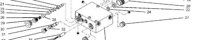

Personal injury can result from being struck by parts propelled by a released spring force.
Make sure to wear all necessary protective equipment.
Follow the recommended procedure and use all recommended tooling to release the spring force.
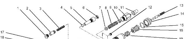
1. Remove plug (1), spool (2), and spring (3).
2. Remove plug (6), screw (5), and O-ring seal (4).
3. Remove cap (11), plug assembly (10), seat (9), spring (8), and seat (7).
4. Remove five plugs (12).
5. Remove lever (13), boot (14), retaining ring (15), spring assembly (16), spring (19), pipe (20), washer (22), and seal (24).
6. Remove plug (27) and plug (43).
7. Remove plug (30), plug (29), spring (26), case (28), spring (25), sleeve (23), seal (21), backup ring (18), and sleeve (17).
8. Remove plug (33), O-ring seal (32), and sleeve (31).
9. Remove plug (37), collar (36), O-ring seal (38), pin (39), spring (40), sleeve (41), pin (42), spring (35), and sleeve (34) from block (44). Copyright 1993 - 2024 Caterpillar Inc.
Mon Aug 19 02:22:43 UTC+0530 2024
Product: WHEELED EXCAVATOR
Model: M313D WHEELED EXCAVATOR K3D
Configuration: M313D Excavator K3D00001-UP (MACHINE) POWERED BY C4.4 Engine
Disassembly and Assembly
M313D Wheeled Excavator Machine Systems
Media Number -KENR6025-04
Brake Control Valve - Remove
SMCS - 4265-011
Removal Procedure Table 1 Required Tools
Start By:
a. Release the hydraulic system pressure. Refer to Disassembly and Assembly, "Hydraulic System Pressure - Release".
Note: SERVICE DATA: TOOLING (ZZ) WILL NOT BE IDENTIFIED IN PHOTOGRAPHS IN THE REMOVAL OR THE INSTALLATION. THIS TOOLING IS SHOWN IN ORDER TO ASSIST THE EXPERIENCED SERVICEMAN.
Note: Press and release the brake pedal until all residual pressure is released from the braking system.
NOTICE
Care must be taken to ensure that fluids are contained during performance of inspection, maintenance, testing, adjusting, and repair
of the product. Be prepared to collect the fluid with suitable containers before opening any compartment or disassembling any component containing fluids.
Refer to Special Publication, NENG2500, "Dealer Service Tool Catalog" for tools and supplies suitable to collect and contain fluids on Cat products.
Dispose of all fluids according to local regulations and mandates.
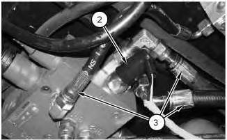
3. Disconnect harness assembly (2) and hose assemblies (3).
3
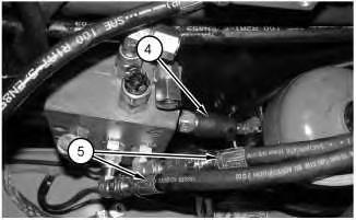
4. Disconnect harness assembly (4) and hose assemblies (5).
4
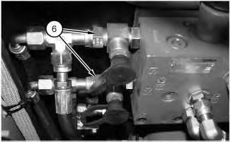
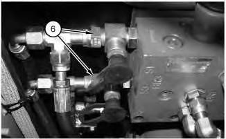
5. Disconnect hose assemblies (6).
5
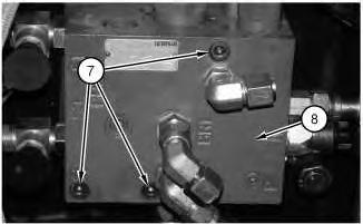
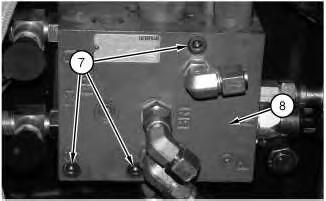
6. Remove bolts (7) and remove brake control valve (8). Copyright 1993 - 2024 Caterpillar Inc.
Product: WHEELED EXCAVATOR
Model: M313D WHEELED EXCAVATOR K3D
Configuration: M313D Excavator K3D00001-UP (MACHINE) POWERED BY C4.4 Engine
Disassembly and Assembly
M313D Wheeled Excavator Machine Systems
Media Number -KENR6025-04 Publication Date -01/03/2017 Date Updated -06/03/2017
SMCS - 5051-012-MV; 5051-012
Installation Procedure
NOTICE
Keep all parts clean from contaminants.
Contamination of the hydraulic system with foreign material will reduce the service life of the hydraulic system components.
To prevent contaminants from entering the hydraulic system, always plug or cap the lines, fittings, or hoses as they are disconnected. Cover any disassembled components and clean them properly before assembly.
Clean the hydraulic system properly after any major component exchange or especially after a component failure, to remove any contamination.
NOTICE
Keep all parts clean from contaminants.
Contaminants may cause rapid wear and shortened component life.
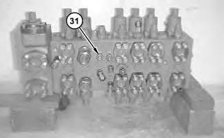
Illustration 1 g01404707
1. Install fittings (31).
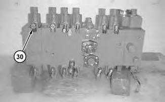
Illustration 2
2. Install fittings (30).
g01404704
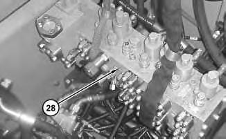
Illustration 3
g01404693
3. Use a suitable lifting device in order to install main control valve (28). The weight of main control valve (28) is approximately 159 kg (350 lb).
4
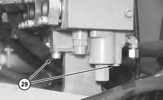
4. Install bolts (29). Repeat this step for the opposite side.
5
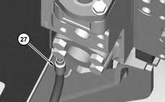
5. Connect hose assembly (27).
6
7
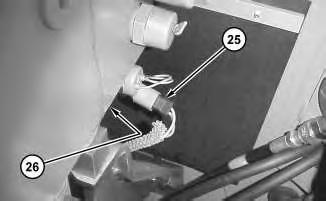
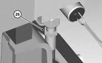
6. Connect harness assembly (26). Connect hose assembly (25).
8
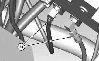
7. Connect hose assemblies (24).
9
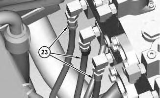
8. Connect hose assemblies (23).
10
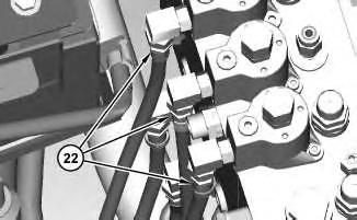
9. Connect hose assemblies (22).
11
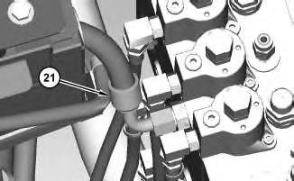
10. Connect hose assembly (21).
12
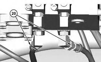
11. Connect hose assemblies (20).
13
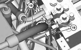
12. Connect hose assemblies (19). Connect hose assembly (18).
14
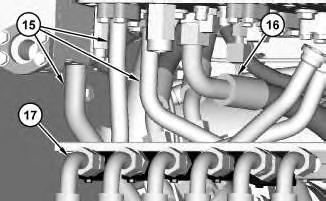
13. Position hose assemblies (17). Connect hose assembly (16). Connect tube assemblies (15).
15
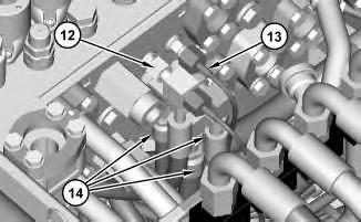
14. Connect hose assemblies (14). Connect hose assembly (13). Connect fitting (12).
16
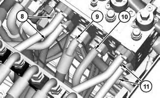
15. Connect tube assemblies (11). Connect hose assembly (10). Connect hose assembly (9). Connect tube assemblies (8).
17
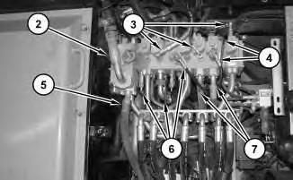
16. Connect hose assemblies (7). Connect hose assemblies (6). Connect hose assembly (5). Connect hose assemblies (4). Connect hose assemblies (3). Connect hose assembly (2).
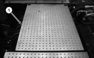
17. Install cover assembly (1).
This is the sample of the manual click on the download link for complete manual
For some reason if link does not work download this pdf and then click