Tip; Use Bookmarks panel to navigate
Product: INTEGRATED TOOLCARRIER
Model: IT38G II INTEGRATED TOOLCARRIER JAN
Configuration: IT38G II Integrated Toolcarrier JAN00001-UP (MACHINE) POWERED BY 3126B Engine
Operation and Maintenance Manual
938G Series II Wheel Loader and IT38G Series II Integrated Toolcarrier
Foreword
Literature Information
s00037320
This manual should be stored in the operator's compartment in the literature holder or seat back literature storage area.
This manual contains safety information, operation instructions, transportation information, lubrication information and maintenance information.
Some photographs or illustrations in this publication show details or attachments that can be different from your machine. Guards and covers might have been removed for illustrative purposes.
Continuing improvement and advancement of product design might have caused changes to your machine which are not included in this publication. Read, study and keep this manual with the machine.
Whenever a question arises regarding your machine, or this publication, please consult your Cat dealer for the latest available information.
Safety
The safety section lists basic safety precautions. In addition, this section identifies the text and locations of warning signs and labels used on the machine.
Read and understand the basic precautions listed in the safety section before operating or performing lubrication, maintenance and repair on this machine.
Operation
The operation section is a reference for the new operator and a refresher for the experienced operator. This section includes a discussion of gauges, switches, machine controls, attachment controls, transportation and towing information.
Photographs and illustrations guide the operator through correct procedures of checking, starting, operating and stopping the machine.
Operating techniques outlined in this publication are basic. Skill and techniques develop as the operator gains knowledge of the machine and its capabilities.
Maintenance
The maintenance section is a guide to equipment care. The Maintenance Interval Schedule (MIS) lists the items to be maintained at a specific service interval. Items without specific intervals are listed under the "When Required" service interval. The Maintenance Interval Schedule lists the page number for the step-by-step instructions required to accomplish the scheduled maintenance. Use the Maintenance Interval Schedule as an index or "one safe source" for all maintenance procedures.
Maintenance Intervals
Use the service hour meter to determine servicing intervals. Calendar intervals shown (daily, weekly, monthly, etc.) can be used instead of service hour meter intervals if they provide more convenient servicing schedules and approximate the indicated service hour meter reading. Recommended service should always be performed at the interval that occurs first.
Under extremely severe, dusty or wet operating conditions, more frequent lubrication than is specified in the maintenance intervals chart might be necessary.
Perform service on items at multiples of the original requirement. For example, at every 500 service hours or 3 months, also service those items listed under every 250 service hours or monthly and every 10 service hours or daily.
California Proposition 65 Warning
Diesel engine exhaust and some of its constituents are known to the State of California to cause cancer, birth defects, and other reproductive harm.
Battery posts, terminals and related accessories contain lead and lead compounds. Wash hands after handling.
Certified Engine Maintenance
Proper maintenance and repair is essential to keep the engine and machine systems operating correctly. As the heavy duty off-road diesel engine owner, you are responsible for the performance of the required maintenance listed in the Owner Manual, Operation and Maintenance Manual, and Service Manual.
It is prohibited for any person engaged in the business of repairing, servicing, selling, leasing, or trading engines or machines to remove, alter, or render inoperative any emission related device or element of design installed on or in an engine or machine that is in compliance with the regulations (40 CFR Part 89). Certain elements of the machine and engine such as the exhaust system, fuel system, electrical system, intake air system and cooling system may be emission related and should not be altered unless approved by Caterpillar.
Machine Capacity
Additional attachments or modifications may exceed machine design capacity which can adversely affect performance characteristics. Included would be stability and system certifications such as brakes, steering, and rollover protective structures (ROPS). Contact your Cat dealer for further information.
Cat Product Identification Number
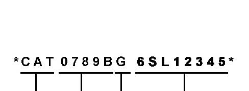
Effective First Quarter 2001 the Cat Product Identification Number (PIN) has changed from 8 to 17 characters. In an effort to provide uniform equipment identification, Caterpillar and other construction equipment manufacturers are moving to comply with the latest version of the product identification numbering standard. Non-road machine PINs are defined by ISO 10261. The new PIN format will apply to all Cat machines and generator sets. The PIN plates and frame marking will display the 17 character PIN. The new format will look like the following:
Illustration 1 g00751314
Where:
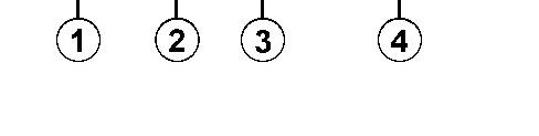
1. Caterpillar's World Manufacturing Code (characters 1-3)
DOWNLOAD LINK
For some reason if link does not work download this pdf and then click
2. Machine Descriptor (characters 4-8)
3. Check Character (character 9)
4. Machine Indicator Section (MIS) or Product Sequence Number (characters 10-17). These were previously referred to as the Serial Number.
Machines and generator sets produced before First Quarter 2001 will maintain their 8 character PIN format.
Components such as engines, transmissions, axles, etc. and work tools will continue to use an 8 character Serial Number (S/N).
Copyright 1993 - 2025 Caterpillar Inc. All Rights Reserved. Private Network For SIS Licensees.
Product: INTEGRATED TOOLCARRIER
Model: IT38G II INTEGRATED TOOLCARRIER JAN
Configuration: IT38G II Integrated Toolcarrier JAN00001-UP (MACHINE) POWERED BY 3126B Engine
Operation and Maintenance Manual
938G II Wheel Loader and IT38G II Integrated Toolcarrier
Media Number -SEBU7581-10
Publication Date -01/05/2019
Articulation Bearings - Lubricate
SMCS - 7057-086-BD; 7065-086-BD; 7066-086-BD
Date Updated -31/05/2019
Crushing Hazard. Insure that the machine ignition switch is in the OFF position and that the parking brake is engaged before entering the articulation area. Failure to do so could result in serious injury or death.
1
g00107435
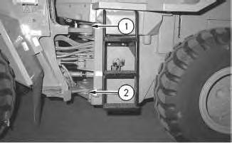
Note: On certain models, the fittings will be accessible from the left side of the machine.
Wipe off the fittings before any lubricant is applied.
Apply lubricant through fittings (1) and (2) on the articulation hitches.
Wed Feb 26 15:48:15 UTC+0530 2025
i02405470
Illustration
Product: INTEGRATED TOOLCARRIER
Model: IT38G II INTEGRATED TOOLCARRIER JAN
Configuration: IT38G II Integrated Toolcarrier JAN00001-UP (MACHINE) POWERED BY 3126B Engine
Operation and Maintenance Manual
938G II Wheel Loader and IT38G II Integrated Toolcarrier
Media Number -SEBU7581-10
Publication Date -01/05/2019 Date Updated -31/05/2019
Axle Oil Cooler Magnetic Filter - Clean/Replace
SMCS - 3004-070-MGS; 3004-510-MGS
Illustration 1
g00110548
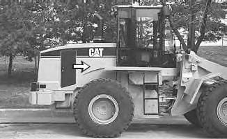
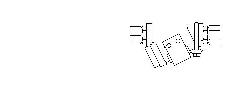
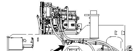
1. Open the engine hood. The magnetic filters for the axle oil cooler are located on the right side of the engine.
i01700204
Illustration 2 g00875415
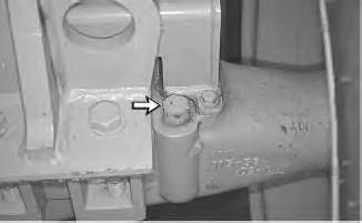
2. Remove the two magnetic filters from the axle oil cooler lines.
3. Wash the filters in a clean nonflammable solvent. Inspect the filters for damage. Replace the filters if the filters are damaged.
Note: If the oil samples for the differential oil show a particle count that is higher than normal, clean the filters for the axle oil cooler at an earlier interval.
4. Install the two filters for the axle oil cooler.
5. Close the engine hood.
6. Start the engine. Operate the machine in order to circulate the oil.
7. Stop the engine.
Illustration 3
Front Differential and Final Drive Filler Plug
g00277215
Illustration 4
Rear Differential and Final Drive Filler Plug
g00110469
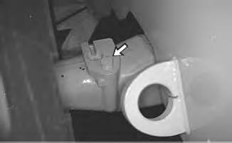
8. Remove the dipstick/fill plug for the front differential and the dipstick/fill plug for the rear differential. Check the oil level.
9. Maintain the oil level between the ADD mark and the FULL mark on the dipstick/fill plug. Add oil, if necessary. Replace the dipstick/fill plug.
Copyright 1993 - 2025 Caterpillar Inc. All Rights Reserved. Private Network For SIS Licensees. Wed Feb 26 15:48:30 UTC+0530 2025
Product: INTEGRATED TOOLCARRIER
Model: IT38G II INTEGRATED TOOLCARRIER JAN
Configuration: IT38G II Integrated Toolcarrier JAN00001-UP (MACHINE) POWERED BY 3126B Engine
Operation and Maintenance Manual
938G II Wheel Loader and IT38G II Integrated Toolcarrier
Media Number -SEBU7581-10
Publication Date -01/05/2019
Axle Oscillation Bearings - Lubricate
SMCS - 3268-086-BD; 3278-086-BD
Date Updated -31/05/2019
Crushing Hazard. Insure that the machine ignition switch is in the OFF position and that the parking brake is engaged before entering the articulation area. Failure to do so could result in serious injury or death.
1
Wipe off the fittings before you apply any lubricant.
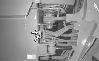
Apply lubricant through two remote fittings near the articulation hitch on the right side of the machine.
Copyright 1993 - 2025 Caterpillar Inc. All Rights Reserved. Wed Feb 26 15:48:46 UTC+0530 2025
i02405487
Illustration
Product: INTEGRATED TOOLCARRIER
Model: IT38G II INTEGRATED TOOLCARRIER JAN
Configuration: IT38G II Integrated Toolcarrier JAN00001-UP (MACHINE) POWERED BY 3126B Engine
Operation and Maintenance Manual
938G II Wheel Loader and IT38G II Integrated Toolcarrier
Media Number -SEBU7581-10
Publication Date -01/05/2019
Backup Alarm - Test
SMCS - 7406-081
Date Updated -31/05/2019
i01808955
Turn the engine start switch key to the ON position in order to perform the test.
Apply the service brake. Move the transmission direction control lever to REVERSE position.
The backup alarm should immediately sound. The backup alarm will continue to sound until the transmission direction control lever is moved to the NEUTRAL position or to the FORWARD position.
Illustration 1
g00924571
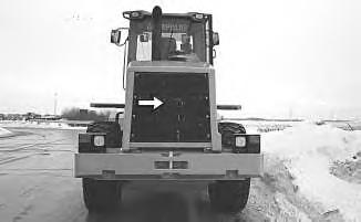
The backup alarm is mounted in the back of the machine behind the rear grill.
Illustration 2 g00844425
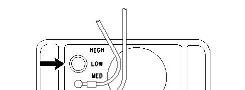
A three-position switch at the rear of the backup alarm regulates the sound of the alarm. The sound of the alarm can be adjusted to HIGH, LOW, or MEDIUM.
The alarm is set at the maximum sound level when the machine is shipped from the factory. The setting should remain on high, unless the job site requires a lower sound level.
Copyright 1993 - 2025 Caterpillar Inc. All Rights Reserved. Private Network For SIS Licensees.
Wed Feb 26 15:49:04 UTC+0530 2025
Product: INTEGRATED TOOLCARRIER
Model: IT38G II INTEGRATED TOOLCARRIER JAN
Configuration: IT38G II Integrated Toolcarrier JAN00001-UP (MACHINE) POWERED BY 3126B Engine
Operation and Maintenance Manual
938G II Wheel Loader and IT38G II Integrated Toolcarrier
Media Number -SEBU7581-10
Battery - Clean
SMCS - 1401-070
Publication Date -01/05/2019
Date Updated -31/05/2019
i01894639
Illustration 1 g00985882
The batteries are located in the battery compartment on the left rear bumper.
Clean the battery surfaces with a clean cloth. Keep the terminals clean and keep the terminals coated with petroleum jelly. Install the post covers after you coat the terminal posts with petroleum jelly.
Copyright 1993 - 2025 Caterpillar Inc. All Rights Reserved.
Private Network For SIS Licensees.
Wed Feb 26 15:49:21 UTC+0530 2025
Product: INTEGRATED TOOLCARRIER
Model: IT38G II INTEGRATED TOOLCARRIER JAN
Configuration: IT38G II Integrated Toolcarrier JAN00001-UP (MACHINE) POWERED BY 3126B Engine
Operation and Maintenance Manual
938G II Wheel Loader and IT38G II Integrated Toolcarrier Media Number -SEBU7581-10
Publication Date -01/05/2019 Date Updated -31/05/2019
Battery - Recycle
SMCS - 1401-561
Always recycle a battery. Never discard a battery.
Always return used batteries to one of the following locations:
• A battery supplier
• An authorized battery collection facility
• Recycling facility
i07746330
Copyright 1993 - 2025 Caterpillar Inc. All Rights Reserved. Private Network For SIS Licensees. Wed Feb 26 15:49:35 UTC+0530 2025
Product: INTEGRATED TOOLCARRIER
Model: IT38G II INTEGRATED TOOLCARRIER JAN
Configuration: IT38G II Integrated Toolcarrier JAN00001-UP (MACHINE) POWERED BY 3126B Engine
Operation and Maintenance Manual
938G II Wheel Loader and IT38G II Integrated Toolcarrier
Media Number -SEBU7581-10
Publication Date -01/05/2019
Battery Hold-Down - Tighten
SMCS - 7257-527
Date Updated -31/05/2019
i01894716
Illustration 1 g00985882
The batteries are located in the battery compartment on the left rear bumper.
Tighten the hold-downs for the battery in order to prevent the batteries from moving during machine operation.
Copyright 1993 - 2025 Caterpillar Inc. All Rights Reserved. Private Network For SIS Licensees.
Wed Feb 26 15:49:52 UTC+0530 2025
Product: INTEGRATED TOOLCARRIER
Model: IT38G II INTEGRATED TOOLCARRIER JAN
Configuration: IT38G II Integrated Toolcarrier JAN00001-UP (MACHINE) POWERED BY 3126B Engine
Operation and Maintenance Manual
938G II Wheel Loader and IT38G II Integrated Toolcarrier
Media Number -SEBU7581-10
Publication Date -01/05/2019
Battery or Battery Cable - Inspect/Replace
SMCS - 1401-040; 1401-510; 1402-040; 1402-510
Date Updated -31/05/2019
i08185587
Personal injury may occur from failure to properly service the batteries.
Batteries give off flammable fumes that can explode. Electrolyte is an acid and can cause personal injury if it contacts the skin or eyes.
Prevent sparks near the batteries. Sparks could cause vapors to explode. Do not allow jumper cable ends to contact each other or the engine. Improper jumper cable connections can cause an explosion.
Always wear protective glasses when working with batteries.
1. Prepare the machine for maintenance. Refer to Operation and Maintenance Manual, Prepare the Machine for Maintenance.
2. Turn the engine start switch key OFF. Turn all of the switches OFF.
3. Turn the battery disconnect switch OFF. Remove the key.
4. Disconnect the negative battery cable from the disconnect switch.
Note: Do not allow the disconnected battery cable to contact the disconnect switch.
5. Disconnect the negative battery cable at the battery.
6. Disconnect the positive battery cable at the battery.
7. Inspect the battery terminals for corrosion. Inspect the battery cables for wear or damage.
8. Make any necessary repairs. If necessary, replace the battery cables or the battery.
9. Connect the positive battery cable at the battery.
10. Connect the negative battery cable at the battery.
11. Connect the battery cable at the battery disconnect switch.
12. Install the key and turn the battery disconnect switch ON.
Recycle the Battery
Always recycle a battery. Never discard a battery.
Always return used batteries to one of the following locations:
• A battery supplier
• An authorized battery collection facility
• Recycling facility
Product: INTEGRATED TOOLCARRIER
Model: IT38G II INTEGRATED TOOLCARRIER JAN
Configuration: IT38G II Integrated Toolcarrier JAN00001-UP (MACHINE) POWERED BY 3126B Engine
Operation and Maintenance Manual
938G II Wheel Loader and IT38G II Integrated Toolcarrier Media Number -SEBU7581-10 Publication Date -01/05/2019 Date Updated -31/05/2019
Belt - Inspect/Adjust/Replace
SMCS - 1397-510; 1397-025; 1397-040
i02211920
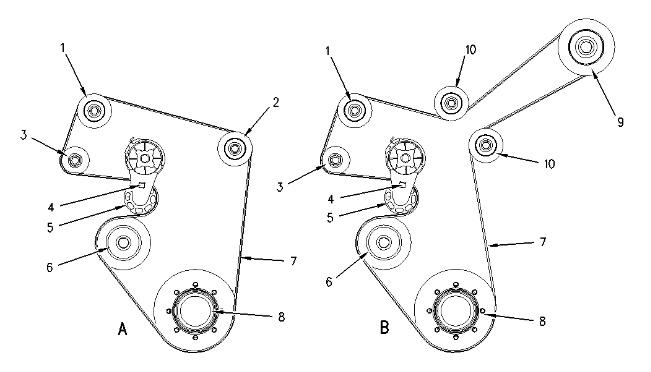
Your machine is equipped with a single serpentine belt. Stop the engine. Open the rear hood. The belt is located at the rear of the engine. Inspect the condition of the serpentine belt. Replace the belt if the belt is cracked or frayed.
Illustration 1 g00752925
(1) Idler pulley
(2) Idler pulley
(3) Alternator
(4) Square hole
(5) Tensioner
(6) Water pump
(7) Serpentine belt
(8) Crankshaft pulley
(9) Compressor (If Equipped)
(10) Idler pulley
A tensioner (5) keeps the correct tension on the belt (7). Insert a ratchet with a square drive into the hole (4). Rotate the tensioner clockwise in order to relieve tension on the belt. Remove the belt.
Install the new belt. Be sure that the new belt is routed correctly, as shown. View (A) represents machines that are not equipped with an air conditioner. View (B) represents machines that are equipped with an air conditioner. Rotate the tensioner clockwise in order to install the new belt. Release the tensioner when the new belt is installed. The correct tension will automatically be applied.
Belt for the Axle Oil Cooler Pump (If Equipped)
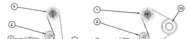
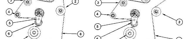
Your machine is equipped with a single serpentine belt. Stop the engine. Open the rear hood. The belt is located at the rear of the engine. Inspect the condition of the serpentine belt. Replace the belt if the belt is cracked or frayed.
(1) Axle oil cooler pump
(2) Idler pulley
(3) Idler pulley
(4) Alternator
(5) Square hole
(6) Tensioner
(7) Water pump
(8) Serpentine belt
(9) Crankshaft pulley
(10) Compressor (If Equipped)
A tensioner (6) keeps the correct tension on the belt (8). Insert a ratchet with a square drive into the hole (5). Rotate the tensioner clockwise in order to relieve tension on the belt. Remove the belt.
Install the new belt. Be sure that the new belt is routed correctly, as shown. View (A) represents machines that are not equipped with an air conditioner. View (B) represents machines that are equipped with an air conditioner. Rotate the tensioner clockwise in order to install the new belt. Release the tensioner when the new belt is installed. The correct tension will automatically be applied.
Copyright 1993 - 2025 Caterpillar Inc. All Rights Reserved. Private Network For SIS Licensees.
Wed Feb 26 15:50:26 UTC+0530 2025
Product: INTEGRATED TOOLCARRIER
Model: IT38G II INTEGRATED TOOLCARRIER JAN
Configuration: IT38G II Integrated Toolcarrier JAN00001-UP (MACHINE) POWERED BY 3126B Engine
Operation and Maintenance Manual
938G II Wheel Loader and IT38G II Integrated Toolcarrier
Media Number -SEBU7581-10
Publication Date -01/05/2019 Date Updated -31/05/2019
Brake Accumulator - Check
SMCS - 4263-535
Illustration 1 g00877459
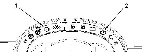
1. Turn the engine start switch to the ON position. The alert indicator (1) for brake oil pressure should come on if the braking system is not at normal operating pressure.
2. Start the engine. Run the engine at half speed for two minutes in order to increase the accumulator pressure. The alert indicator (1) for brake oil pressure should go off.
3. Stop the engine. Apply the service brake pedal and release the service brake pedal until the alert indicator for brake oil pressure comes on. This will decrease the accumulator pressure. A minimum of five applications of the service brake pedal are required.
Note: The parking brake indicator light (2) will be on when the alert indicator for brake oil pressure comes on.
i01703170
4. If the alert indicator comes on after less than five applications of the brake, measure the accumulator precharge pressure. An authorized Caterpillar dealer can measure the nitrogen gas pressure in the accumulator. Use only dry nitrogen gas for recharging.
Copyright 1993 - 2025 Caterpillar Inc. All Rights Reserved. Private Network For SIS Licensees.
Wed Feb 26 15:50:41 UTC+0530 2025
Product: INTEGRATED TOOLCARRIER
Model: IT38G II INTEGRATED TOOLCARRIER JAN
Configuration: IT38G II Integrated Toolcarrier JAN00001-UP (MACHINE) POWERED BY 3126B Engine
Operation and Maintenance Manual
938G II Wheel Loader and IT38G II Integrated Toolcarrier Media Number -SEBU7581-10
Publication Date -01/05/2019
Brake Discs - Check
SMCS - 4255-535
Date Updated -31/05/2019
i01732078
Reference: For the correct procedure, refer to the Testing and Adjusting Service Manual of the braking system for your machine or consult your Caterpillar dealer.
Copyright 1993 - 2025 Caterpillar Inc. All Rights Reserved. Private Network For SIS Licensees.
Wed Feb 26 15:50:56 UTC+0530 2025