



Product: INTEGRATED TOOLCARRIER
Model: IT18 INTEGRATED TOOLCARRIER 7ZB
Configuration: 1T18 INTEGRATED TOOLCARRIER 7ZB00001-UP (MACHINE) POWERED BY 3204 ENGINE
Operation and Maintenance Manual
IT18,IT18B,IT28 AND IT28B INTEGRATED TOOLCARRIERS
Media Number -SEBU6072-02
Publication Date -01/05/1990
After Starting the Engine
Date Updated -11/10/2001
SMCS - 1000; 1400; 4203; 4490; 5070; 5927; 6700; 7000; 7008; 7220; 7327; 7347; 7400; 7451; 7490; 7541; 7604; 7605; 7606
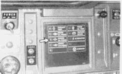
1. Keep the engine speed low until the oil pressure light goes out. If the oil pressure light does not go out within 10 seconds, stop the engine and investigate.
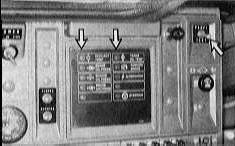
2. Push the panel test switch to the test position to test the indicator lights.
3. If the lights do not come on, make any necessary repairs.
4. If any of the indicator lights stay on, have any necessary repairs made before operating the machine.
5. Look at the operator's panel frequently during operation. If any of the indicator lights come on, stop the machine, if necessary, and investigate.
Product: INTEGRATED TOOLCARRIER
Model: IT18 INTEGRATED TOOLCARRIER 7ZB
Configuration: 1T18 INTEGRATED TOOLCARRIER 7ZB00001-UP (MACHINE) POWERED BY 3204 ENGINE
Operation and Maintenance Manual
IT18,IT18B,IT28 AND IT28B INTEGRATED TOOLCARRIERS
Media Number -SEBU6072-02
Publication Date -01/05/1990
Before Starting the Engine
Date Updated -11/10/2001
SMCS - 1000; 1400; 4203; 4490; 5070; 5927; 6700; 7000; 7008; 7220; 7327; 7347; 7400; 7451; 7490; 7541; 7604; 7605; 7606
Walk-Around Inspection
Hot oil and components can cause personal injury. Do not allow hot oil or components to contact skin.
At operating temperature, the engine coolant is hot and under pressure.
Steam can cause personal injury.
Check the coolant level only after the engine has been stopped and the fill cap is cool enough to touch with your bare hand.
Remove the fill cap slowly to relieve pressure.
Cooling system conditioner contains alkali. Avoid contact with the skin and eyes to prevent personal injury.
For your own safety and maximum service life of the vehicle, make a thorough walk-around inspection before mounting the machine to start the engine.
Look around and under the machine for such items as loose or missing bolts, trash build-up, oil, coolant or fuel leaks. Inspect the condition and inflation of the tires, condition of hydraulic lines and hoses, condition of the implement and implement linkage.
Remove any trash and debris. Adjust tire inflation as needed. Have any necessary repairs made, loose connections and parts tightened to their specified torques and any missing parts replaced before starting the engine or operating the machine.
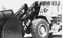
1. Inspect implement for damage or excessive wear.
2. Inspect implement control linkage for damage or excessive wear.
3. Inspect lights for broken bulbs and lenses. Check for loose or frayed wires.
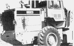
4. Inspect radiator guard for trash build-up.
5. Inspect cooling system for leaks and trash build-up.
6. Inspect engine precleaner for dirt build-up.
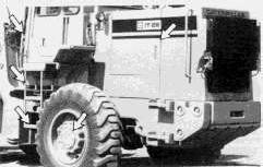
7. Inspect engine compartment for engine oil leaks and trash build-up.
8. Inspect the condition and cleanliness of the steps and handholds. Inspect the Rollover Protective Structure (ROPS) for cracks, damage, etc. See the "Rollover Protective Structure (ROPS)" section in this publication.
9. Inspect differentials (front and rear) under machine for leaks.
This is the sample of the manual click on the download link for complete manual
DOWNLOAD LINK
For some reason if link does not work download this pdf and then click
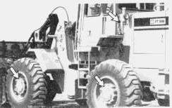
10. Inspect hydraulic system for leaks. Check for loose hose connections. Check for frayed hoses.
11. Inspect final drives (front and rear) for leaks.
12. Be sure covers and guards are firmly in place. Inspect for damage.
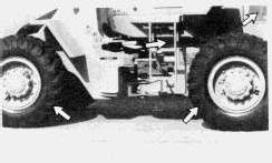
13. Inspect transmission for leaks.
14. Inspect tires (front and rear) for damage and proper inflation.
15. Inspect the wheel brakes for oil leaks.
16. Inspect belts for cracks, breaks or other damage.
NOTE: Belts for multiple groove pulleys must be replaced as matched sets.
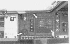
17. Inspect instrument panel for broken gauges and indicator lights. Inspect operator's compartment for cleanliness.
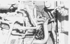
Measure the crankcase oil level. The level should be above the ADD mark on the ENGINE STOPPED side of the dipstick.
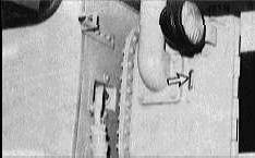
Observe the hydraulic system oil level. Maintain the oil level above the ADD mark in the sight gauge.
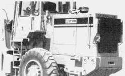
Inspect the precleaner. Empty and clean the cup, if necessary.
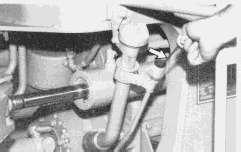
Measure the transmission oil level. Oil level must be at the "MIN SAFE START - COLD OIL" mark on the dipstick.
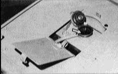
Observe the coolant level. Maintain the coolant within 1 cm (1/2 inch) of the bottom of the fill pipe.
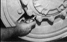
Measure the tire pressure. See the topic "Tire Inflation Information."
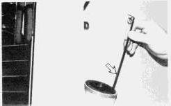
Measure the fuel level. Fill the fuel tank after each day of operation to help prevent condensation in the tank.
Copyright 1993 - 2024 Caterpillar Inc. All Rights Reserved. Private Network For SIS Licensees. Wed Mar 27 23:59:46 UTC+0530 2024
Product: INTEGRATED TOOLCARRIER
Model: IT18 INTEGRATED TOOLCARRIER 7ZB
Configuration: 1T18 INTEGRATED TOOLCARRIER 7ZB00001-UP (MACHINE) POWERED BY 3204 ENGINE
Operation and Maintenance Manual
IT18,IT18B,IT28 AND IT28B INTEGRATED TOOLCARRIERS
Media Number -SEBU6072-02
Publication Date -01/05/1990
Coolant, Fuel and Lubricant Specifications
Date Updated -11/10/2001
SMCS - 1000; 1400; 4203; 4490; 5070; 5927; 6700; 7000; 7008; 7220; 7327; 7347; 7400; 7451; 7490; 7541; 7604; 7605; 7606
Coolant Specifications
NOTICE
Use a mixture of water, ethylene glycol (antifreeze) and cooling system conditioner. Pure, undiluted antifreeze will freeze at -23°C (-10°F).
Excessive coolant conditioner (greater than the recommended 6% initial fill) together with concentrations of antifreeze greater than 65% cause deposits to form and may result in radiator tube blockage and overheating.
Do not use Caterpillar cooling system conditioner or coolant conditioner elements with Dowtherm 209 Full-Fill coolant. Follow the instructions provided with the Dowtherm 209 Full-Fill coolant.
Refer to "Know Your Cooling System," Form SEBD0518, for more detailed specifications.
Water
Acceptable water for use in the ethylene glycol and water mixture is shown in the chart below:
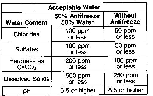
ppm=parts per million
Antifreeze
Use the correct amount of ethylene glycol mixed with water, to provide freeze protection to the lowest expected outside temperature.
Conditioner
NOTICE
Always add liquid cooling system conditioner to water, or install a coolant conditioner element (if equipped). Never use water only.
Never use both liquid cooling system conditioner and a coolant conditioner element (if equipped) at the same time.
Use Caterpillar liquid cooling system conditioner or a coolant conditioner element (if equipped). This will provide a 3% to 6% concentration of conditioner in the cooling system to help prevent corrosion.
Conditioner can be purchased from your Caterpillar dealer.
Fuel Specifications and Information
Types of Fuel
Caterpillar diesel engines have the ability to burn a wide variety of fuels. These fuels are divided into two general groups, preferred and permissible.
The preferred fuels provide maximum engine service life and performance. They are distillate fuels. They are commonly called diesel fuel, furnace oil, gas oil or kerosene.
The permissible fuels are crude oils or blended fuels. Use of these fuels can result in higher maintenance costs and reduced engine service life.
Refer to "Fuels for Caterpillar Diesel Engines," Form SEHS7067, for a detailed summary of preferred and permissible fuels and their specifications.
Refer to S.A.E. J313 Diesel Fuels for information about better quality fuels, such as ignition quality, gravity/density, viscosity, cloud point, sulfur content, etc.
Fuel Sulfur Content
The percentage of sulfur in the fuel will affect the engine oil recommendations. See "Engine Oils" under "Lubricant Specifications."
Fuel sulfur is chemically changed during combustion to form sulfuric acid. The acid chemically attacks metal surfaces and causes corrosive wear. Higher engine oil TBN (Total Base Number) values are essential to minimize corrosive wear.
Periodically request fuel sulfur content information from your fuel supplier. Fuel sulfur content can change with each bulk delivery.
Fuel Cetane Requirement
The minimum fuel cetane number recommended for the direct injection engine is 40.
Fuel Cloud Point
Fuel waxing can plug the fuel filters in cold weather. The fuel cloud point must be below the temperature of the surrounding air to prevent filter waxing and power loss. Fuel heating attachments are available from your Caterpillar dealer to minimize fuel filter waxing.
Lubricant Specifications
The abbreviations listed below follow S.A.E. J754 nomenclature. The classifications follow S.A.E. J183 classifications. The MIL specifications are U.S.A. Military Specifications. These definitions will be of assistance in purchasing lubricants. The recommended oil viscosities are found on the "Lubricant Viscosity Recommendations" chart.
The prefix "SPC" is a general abbreviation used by Caterpillar to identify special oils such as synthetics or semi-synthetic oils.
Engine Oils
Use oils that meet the Engine Service Classification CD/SE or CD/SF (MIL-L-2104D).
Consult the "EMA Lubricating Oils Data Book," Form SEBU5939, for a listing of CD/SE or CD/SF oil brands.
The percentage of sulfur in the fuel will affect the engine oil recommendations. If the fuel has over 0.5% sulfur content, the CD/SE or CD/SF engine oil must have a TBN of 20 times the percentage of fuel sulfur (TBN as measured by the ASTM D-2896 method). If the sulfur content is greater than 1.5% by weight, use an oil with a TBN of 30 and reduce the oil change interval by one half. Consult your Caterpillar dealer for correct engine oil recommendations.
Higher TBN values are essential to retard the corrosive damage to metal engine parts.
Your oil supplier should be able to furnish the correct oils.
Power Train System Oil - Differentials and Final Drives, Transmission, Torque Converter and Clutch Oil (CD/TO-2)
Use Service Classification CD oils that have satisfactory performance in the Caterpillar Oil Test Number TO-2. These oils are referred to as Service Classification CD/TO-2 oils.
Hydraulic Oils (HYDO)
Use Engine Service Classification CC (MIL-L-2104B), CC/SF (MIL-L-46152B), CD (MIL-L2104D) or industrial-type hydraulic oils that are certified by the oil supplier to have antiwear, antifoam, antirust, and antioxidation additive properties for heavy duty use.
Lubricating Grease (MPGM)
Use Multipurpose-type grease (MPGM) which contains 3% to 5% molybdenum disulfide. NLGI No. 2 Grade is suitable for most temperatures. Use NLGI No. 1 or No. 0 Grade for extremely low temperatures.
Hydraulic Brake Fluid (BF)
Use heavy duty hydraulic brake fluid certified by the oil supplier to meet SAE1703f specifications.
Copyright 1993 - 2024 Caterpillar Inc. All Rights Reserved.
Private Network For SIS Licensees.
Thu Mar 28 00:03:54 UTC+0530 2024
Product: INTEGRATED TOOLCARRIER
Model: IT18 INTEGRATED TOOLCARRIER 7ZB
Configuration: 1T18 INTEGRATED TOOLCARRIER 7ZB00001-UP (MACHINE) POWERED BY 3204 ENGINE
Operation and Maintenance Manual
IT18,IT18B,IT28 AND IT28B INTEGRATED TOOLCARRIERS
Media Number -SEBU6072-02
Publication Date -01/05/1990
Every 10 Service Hours or Daily
Date Updated -11/10/2001
SMCS - 1000; 1400; 4203; 4490; 5070; 5927; 6700; 7000; 7008; 7220; 7327; 7347; 7400; 7451; 7490; 7541; 7604; 7605; 7606
Walk-Around Inspection
Inspect Machine
Lines, Tubes and Hoses
Inspect all hydraulic, pressure oil, fuel, high temperature water, etc., lines, tubes and hoses for damage, excessive wear and recommended torques. Do not use your bare hands to check for leaks.
Replace damaged, worn, etc., lines, tubes and hoses or contact your Caterpillar dealer for repair or replacement.
For other items to be inspected see "Walk-Around Inspection" in the "Before Starting the Engine" section of this publication.
Fuel Tank
Drain Water and Sediment
Escaping fuel is flammable. Do not smoke while draining water and sediment from the fuel tank.
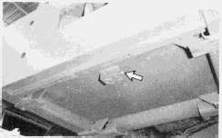
Fuel tank drain valve is located under the right rear of the machine. Open the fuel tank drain valve. Drain water and sediment. Close the drain valve.
Engine Crankcase
Measure Oil Level
Hot oil and components can cause personal injury. Do not allow hot oil or components to contact skin.
The dipstick is located on the right side of the machine. The level is measured with the engine stopped only.
1. Open the access door.
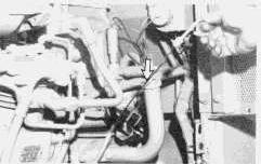
With the engine stopped, the oil level should be between the ADD and FULL marks on the dipstick.
3. If it is necessary to add oil, remove the engine oil filler cap.
4. Add oil to the correct level.
5. Inspect the cap seal. Replace the seal, if it is damaged.
6. Install the oil filler cap.
Hydraulic Tank
At operating temperature, the hydraulic tank is hot and under pressure.
Hot oil can cause burns.
Remove the fill cap only when the engine is stopped, and the cap is cool enough to touch with your bare hand. Remove the fill cap slowly to relieve pressure.
The hydraulic fill tank is located on the left side of the machine.
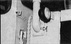
Check the hydraulic oil level in the sight gauge. When the oil is cold, the oil level should be just above the ADD mark. When the oil is hot, it should fill the sight gauge completely.
1. If it is necessary to add oil, remove the hydraulic tank cap slowly to relieve any pressure. Add oil to bring the oil level just above the ADD mark in the sight gauge.
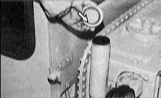
2. Inspect the hydraulic tank cap gasket. Replace the gasket, if it is damaged.
3. Install the hydraulic tank cap.
Air Reservoir
Drain Moisture and Sediment
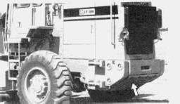
Drain valve is located under the right rear of the machine. Drain valve access is through the hole in the guard.

Open the drain valve to drain any moisture and sediment. Close the valve.
NOTE: Your machine may be equipped with an additional air tank for the parking brake. If so, follow the same procedure to drain moisture and sediment from the second air tank.
NOTE: Your machine may be equipped with an air dryer. If so, check the air tank to see if it is collecting water or oil. Some water is normal. If excessive water is observed, contact your Caterpillar dealer for more specific maintenance procedures.
Radiator
Inspect Condition of Folded Core Radiator
Pressure air can cause personal injury.
When using pressure air for cleaning, wear a protective face shield, protective clothing and protective shoes.
The maximum air pressure must be below 205 kPa (30psi) for cleaning purposes.
Compressed air, high pressure water or steam can be used to remove dust, leaves and general debris from a folded core radiator. Clean as required by condition of radiator.
The use of compressed air is preferred.
Refer to "Know Your Cooling System," Form SEBD0518, for the complete procedure and instructions.
Check Coolant Level
At operating temperature, engine coolant is hot and under pressure.
Steam can cause personal injury.
Check coolant level ONLY when engine is stopped and radiator filler cap is cool enough to touch with your bare hand.
Remove filler cap slowly to relieve pressure.
Cooling system conditioner contains alkali. Avoid contact with skin and eyes to prevent personal injury.
Use all cleaning solutions with care.
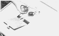
1. Observe the coolant level with the engine stopped and cool. Remove the radiator cap slowly to relieve the pressure.
2. Maintain the coolant level 1 cm (1/2 inch) below the filler neck.
3. Add coolant, if necessary, to bring the coolant level to within 1 cm (1/2 inch) below the filler neck.
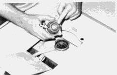
4. Inspect the radiator cap gasket and replace it if it is damaged. Install the radiator cap.
Measure Oil Level
Hot oil and components can cause injury. Do not allow hot oil or components to contact the skin.
The transmission oil level can be checked with the oil cold or hot.
The machine must be parked on level ground and the engine stopped. Lock the transmission control in NEUTRAL.
Lower the bucket with slight down pressure. Apply the parking/secondary brake.
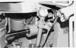
1. Measure the oil level.
With COLD OIL: Maintain oil level at the "MIN SAFE START - COLD OIL" mark on the dipstick.
With HOT OIL: Maintain oil level between the ADD and FULL marks on the "ENGINE AT LOW IDLE" side of the dipstick.
2. Inspect the transmission filler cap gasket. Replace the gasket, if it is damaged.
3. Install the transmission filler cap.
Indicators and Gauges
Test and Inspect
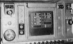
With the engine running, move the panel test switch to the TEST position. All indicator lights should come on and the fault alarm should sound.
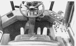
The main fault light should flash when the panel test switch is activated. Investigate and report any malfunction.
Inspect all gauges for broken lenses or indicators. Have any needed repairs made.
Copyright 1993 - 2024 Caterpillar Inc. All Rights Reserved. Private Network For SIS Licensees. Thu Mar 28 00:05:43 UTC+0530 2024
Product: INTEGRATED TOOLCARRIER
Model: IT18 INTEGRATED TOOLCARRIER 7ZB
Configuration: 1T18 INTEGRATED TOOLCARRIER 7ZB00001-UP (MACHINE) POWERED BY 3204 ENGINE
Operation and Maintenance Manual
IT18,IT18B,IT28 AND IT28B INTEGRATED TOOLCARRIERS
Media Number -SEBU6072-02
Publication Date -01/05/1990
Every 100 Service Hours or 2 Weeks
Date Updated -11/10/2001
SMCS - 1000; 1400; 4203; 4490; 5070; 5927; 6700; 7000; 7008; 7220; 7327; 7347; 7400; 7451; 7490; 7541; 7604; 7605; 7606
Rear Axle Trunnion Bearings
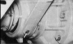
1. Lubricate one fitting in the front trunnion of the rear axle.
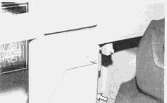
2. Lubricate one fitting in the rear trunnion of the rear axle.
Total of two fittings.
Steering Cylinder Bearings
Lubricate
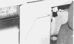
1. Lubricate one fitting in the head end lube block of the steering cylinder on each side of the machine. (Attachment guard group shown).
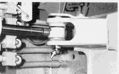
2. Lubricate one fitting in the rod end of the steering cylinder on each side of the machine.
Total of four fittings.
Implement Cylinder and Linkage Bearings
Lubricate
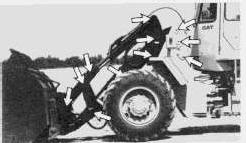
Lubricate eleven fittings on the left side of the machine.
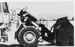
Lubricate eleven fittings on the right side of the machine.
Total of 22 fittings.
Copyright 1993 - 2024 Caterpillar Inc.
Product: INTEGRATED TOOLCARRIER
Model: IT18 INTEGRATED TOOLCARRIER 7ZB
Configuration: 1T18 INTEGRATED TOOLCARRIER 7ZB00001-UP (MACHINE) POWERED BY 3204 ENGINE
Operation and Maintenance Manual
IT18,IT18B,IT28 AND IT28B INTEGRATED TOOLCARRIERS
Media Number -SEBU6072-02
Publication Date -01/05/1990
Every 1000 Service Hours or 6 Months
Date Updated -11/10/2001
SMCS - 1000; 1400; 4203; 4490; 5070; 5927; 6700; 7000; 7008; 7220; 7327; 7347; 7400; 7451; 7490; 7541; 7604; 7605; 7606
Drive Shaft Support Bearing
Lubricate
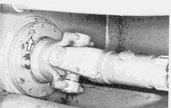
Fitting located in the center of the machine.
Lubricate one fitting.
Drive Shaft Universal Joints
Lubricate
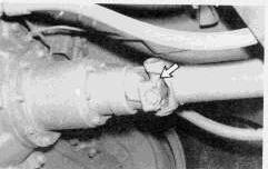
1. Lubricate one fitting in the front shaft universal joint.
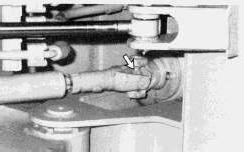
2. Lubricate one fitting in the front universal joint of the center shaft.
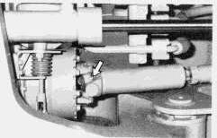
3. Lubricate one fitting in the rear universal joint of the center shaft.
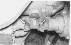
4. Lubricate one fitting in each of the two rear shaft universal joints.
Total of five fittings.
Frame Upper and Lower Pivot Bearings
Lubricate
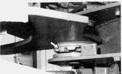
1. Lubricate one fitting at the upper pivot pin.
This is the sample of the manual click on the download link for complete manual
DOWNLOAD LINK
For some reason if link does not work download this pdf and then click