DOWNLOAD LINK
For some reason if link does not work download this pdf and then click
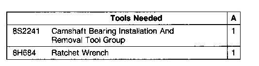
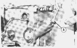
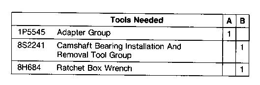
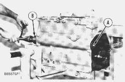
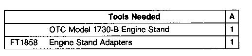
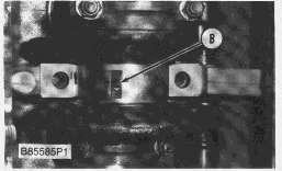
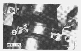
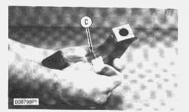
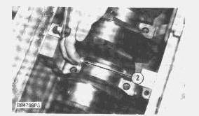
1. Install the camshaft bearings in the cylinder block with tools (A) and (B) as follows:
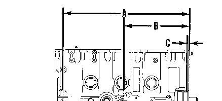
a. Install the center bearing to a depth of 287.5 ± 0.8 mm (11.32 ± .03 in.) [Dimension (A)] from the front surface of the block.
b. Install the rear bearing to a depth of 556.8 ± 0.08 mm (21.92 ± .03 in.) [Dimension (B)] from the front surface of the block.
c. Install the front bearing even (flush) with the front surface of the block and no more than 0.5 mm (.02 in.) [Dimension (C)] deep.
END BY:
a. install flywheel housing
b. install timing gears and plate
c. install camshaft
Copyright 1993 - 2024 Caterpillar Inc. All Rights Reserved.
Private Network For SIS Licensees. Mon Dec 30 23:42:42 UTC+0530 2024
Product: INTEGRATED TOOLCARRIER
Model: IT12 INTEGRATED TOOLCARRIER 2YC
Configuration: IT12 INTEGRATED TOOLCARRIER 2YC00001-UP (MACHINE) POWERED BY 3204 ENGINE
Disassembly and Assembly
3204 VEHICULAR ENGINES
Media Number -SENR3230-00
Camshaft
SMCS - 1210-012; 1210-011
Remove Camshaft
Publication Date -01/10/1985
Date Updated -06/05/2020
SENR32300018
START BY:
a. remove valve lifters
b. remove timing gear cover
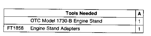
1. Put the engine in position on tooling (A) as shown.
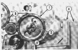
NOTE: To keep the engine timing correct during removal and installation of the camshaft, put a mark on the teeth of the idler gear and camshaft drive gear at location (X). Put a mark on the teeth of the camshaft drive gear and crankshaft drive gear at location (Y).
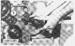
2. Remove bolts (2) and gear (1) from the camshaft.
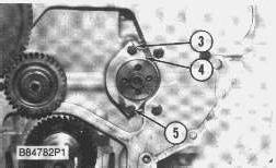
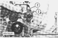
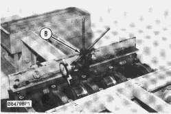
3. Bend the tabs of lock (3) away from bolts (5). Remove bolts (5), lock (3) and washer (4) that hold the camshaft in place.
NOTICE
Use extra care not to damage the camshaft bearings as the camshaft is removed.
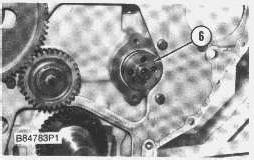
4. Carefully remove camshaft (6) from the cylinder block.
Install Camshaft
1. Put the engine in position on tooling (A).
2. Put clean engine oil on the bearing journals and 2P2506 Thread Lubricant on the cam lobes of the camshaft.
3. Carefully install camshaft (1) in the cylinder block. Hold the camshaft up during installation so the camshaft bearings will not be damaged.
4. Install washer (3), lock (2) and the bolts that hold the camshaft in place. Bend the tabs of the lock against one of the flats of each bolt head.
5. Install two 3/8"-16 NC guide bolts (4) in the end of the camshaft.
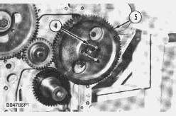
6. Put camshaft drive gear (5) in position on the guide bolts. Make sure the marks on the idler gear and the crankshaft drive gear are in alignment with the marks on the camshaft drive gear.
7. Turn the camshaft, and make sure the "C" mark on the camshaft drive gear is in alignment with the "C" mark on the crankshaft drive gear.
NOTE: If a new gear has been installed, it will be necessary to check the engine timing to make sure the timing is correct. See Remove And Install Fuel Injection Pump Housing And Governor.
8. Install two bolts in the camshaft gear, and remove the guide bolts. Install the remaining bolts in the camshaft drive gear. Tighten the bolts to a torque of 55 ± 7 N·m (41 ± 5 lb.ft.).
END BY:
a. install timing gear cover
b. install valve lifters
Product: INTEGRATED TOOLCARRIER
Model: IT12 INTEGRATED TOOLCARRIER 2YC
Configuration: IT12 INTEGRATED TOOLCARRIER 2YC00001-UP (MACHINE) POWERED BY 3204 ENGINE
Disassembly and Assembly
3204 VEHICULAR ENGINES
Media Number -SENR3230-00
Publication Date -01/10/1985
Connecting Rod Bearings
SMCS - 1219-010
Remove And Install Connecting Rod Bearings
Date Updated -06/05/2020
SENR32300016
START BY:
a. remove oil pan
1. Turn the crankshaft until two pistons are at the bottom center. Remove connecting rod caps (2) from the two connecting rods. Remove the lower half of the rod bearing from the rod bearing cap.
NOTICE
The connecting rod bolts are loose on the connecting rods and can fall out when the nuts are removed.
2. Push connecting rods (1) away from the crankshaft. Remove the upper half of the rod bearing from the connecting rod.
NOTE: Install the connecting rod bearings dry when the clearance checks are made. Put clean engine oil on the connecting rod bearings for final assembly.
NOTICE
Be sure the tabs in the back of the connecting rod bearings are in the tab grooves of the connecting rod and cap.
3. Install the upper half of the rod bearing in the connecting rod, and put the connecting rod in position on the crankshaft.
4. Install the lower half of the rod bearing in the connecting rod cap.
The serviceman must be very careful to use Plastigage correctly. The following points must be remembered:
...Make sure that the backs of the bearings and the bores are clean and dry.
...Make sure that the bearing locking tabs are properly seated in their slots.
...The crankshaft must be free of oil where the Plastigage touches it.
...Put a piece of Plastigage on the crown of the bearing half that is in the cap. Do not allow the Plastigage to extend over the edge of the bearing.
...Install the bearing cap using the correct torque-turn specifications. Do not use an impact wrench. Be careful not to dislodge the bearing when the cap is installed.
...Do not turn the crankshaft with the Plastigage installed.
...Carefully remove the cap, but do not remove the Plastigage. Measure the width of the Plastigage while it is in the bearing cap or on the crankshaft journal. Do this by using the correct scale on the package. Record the measurements.
...Remove the Plastigage before installing the cap.
When using Plastigage, the readings can sometimes be unclear. For example, all parts of the Plastigage are not the same width. Measure the major widths to make sure that they are within the
specification range. Also, experience has shown that when checking clearances tighter than 0.10 mm (.004") the readings may be low by 0.013 to 0.025 mm (.0005 to .0010"). Out-of-round journals can give faulty readings. Also, journal taper may be indicated when one end of the Plastigage is wider than the other.
For complete details concerning measuring bearing clearances, see Engine Bearings And Crankshafts, Form No. SEBD0531.
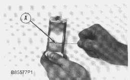
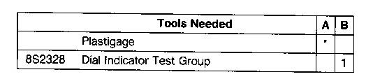
5. Use Plastigage (A) to check the connecting rod bearing clearance.
6. Put Plastigage (A) on the connecting rod bearing.
7. Put 2P2506 Thread Lubricant on the threads of the rod bolts and seat surfaces of the nuts.
NOTICE
When connecting rod caps are installed, make sure the number on the side of the cap is next to and respective with the number on the side of the connecting rod.
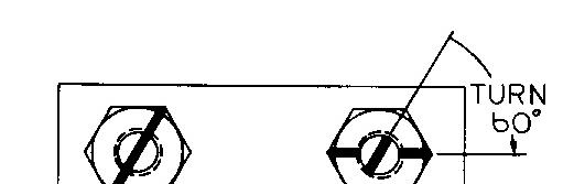
8. Install connecting rod cap (2). Install the nuts. Tighten the nuts to a torque of 41 ± 4 N·m (30 ± 3 lb.ft.). Put a mark on each nut and the end of each bolt. Tighten the nuts 60° ± 5° more.
9. Remove the connecting rod caps. Measure the thickness of the Plastigage. The connecting rod bearing clearance must be 0.043 ± 0.140 mm (.0017 to .0055 in.) for new bearings. The maximum clearance with used bearings is 0.15 mm (.006 in.).
10. Install the connecting rod caps, and tighten the nuts as in Step 8.
11. Do Steps 1 through 9 for the remainder of the connecting rod bearings.
END BY:
Product: INTEGRATED TOOLCARRIER
Model: IT12 INTEGRATED TOOLCARRIER 2YC
Configuration: IT12 INTEGRATED TOOLCARRIER 2YC00001-UP (MACHINE) POWERED BY 3204 ENGINE
Disassembly and Assembly
3204 VEHICULAR ENGINES
Media Number -SENR3230-00
Crankshaft And Gear
SMCS - 1202; 1204-011; 1204-012
Publication Date -01/10/1985
Date Updated -06/05/2020
SENR32300024
Remove Crankshaft And Gear
START BY:
a. remove timing gear cover
b. remove flywheel housing
c. remove pistons and connecting rods
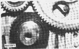
1. Turn the crankshaft until the "C" mark on the crankshaft drive gear is in alignment with the "C" mark on the camshaft drive gear as shown.
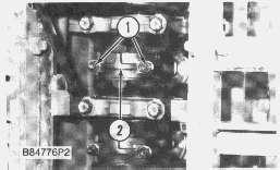
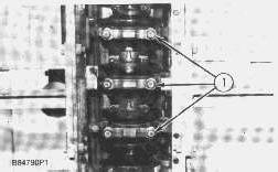
2. Remove the three center main bearing caps (1).
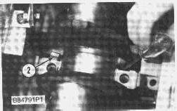
3. Remove thrust bearings (2) from each side of the center crankshaft journal.
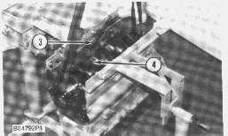
4. Remove bolt (3). Remove the oil pickup tube support strip and the clip from the cylinder block as a unit.
5. Install one of the flywheel bolts in the end of the crankshaft.
6. Fasten a nylon strap and a hoist on crankshaft (4) as shown.
7. Remove the two end caps.
NOTICE
Be careful not to damage the crankshaft journals when the crankshaft is removed.
8. Remove crankshaft (4) from the cylinder block. The weight of the crankshaft is 52 kg (115 lb.).
NOTICE
If new main bearings are not to be installed during crankshaft installation, put identification marks on the original bearings as to their location in the engine.
9. Remove the crankshaft main bearings from the cylinder block and from the main bearing cap.
10. Check the condition of the main bearings and crankshaft. Make reference to Guideline For Reusable Parts: Main And Connecting Rod Bearings, Form No. SEBF8009 and Visual Inspection Of Crankshafts, Form No. SEBF8043.
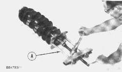
11. Use tooling (A), and remove the drive gear from the crankshaft.
Install Crankshaft And Gear
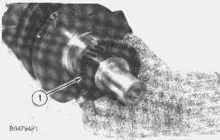
1. Heat the crankshaft drive gear to a maximum temperature of 315° (600°F). Install drive gear (1) on the crankshaft with the "C" mark on the gear toward the pulley end of the crankshaft.
If the crankshaft journals and bores for the block and rods were measured at disassembly and found to be within specifications, no further checks are necessary. However, if the serviceman still wants to measure the bearing clearances, Plastigage is recommended. Lead wire, shim stock or use of a dial bore gauge can damage the bearing surface.
The serviceman must be very careful to use Plastigage correctly. The following points must be remembered:
...Make sure that the backs of the bearings and the bores are clean and dry.
...Make sure that the bearing locking tabs are properly seated in their slots.
...The crankshaft must be free of oil where the Plastigage touches it.
...If the main bearing clearances are checked with the engine upright or on its side, the crankshaft will have to be lifted up with a force equal to the weight of the crankshaft and held against the crown of the bearing. If the crankshaft is not supported, the weight of the crankshaft will cause incorrect readings.
...Put a piece of Plastigage on the crown of the bearing half that is in the cap. Do not allow the Plastigage to extend over the edge of the bearing.
...Install the bearing cap using the correct torque-turn specifications. Do not use an impact wrench. Be careful not to dislodge the bearing when the cap is installed.
...Do not turn the crankshaft with the Plastigage installed.
...Carefully remove the cap, but do not remove the Plastigage. Measure the width of the Plastigage while it is in the bearing cap or on the crankshaft journal. Do this by using the correct scale on the package. Record the measurements.
...Remove the Plastigage before installing the cap.
When using Plastigage, the readings can sometimes be unclear. For example, all parts of the Plastigage are not the same width. Measure the major widths to make sure that they are within the specification range. Also, experience has shown that when checking clearances tighter than 0.10 mm (.004") the readings may be low by 0.013 to 0.025 mm (.0005 to .0010"). Out-of-round journals can give faulty readings. Also, journal taper may be indicated when one end of the Plastigage is wider than the other.
NOTE: For complete details concerning measuring bearing clearances, see Engine Bearings And Crankshafts, Form No. SEBD0531.
NOTICE
Make sure the upper and lower halves of the main bearings are installed so the bearing tabs fit into the notch in the cylinder block and main bearing caps.
2. If the bearings were removed from the engine, clean the bearing surfaces in the cylinder block for the main bearings. Install the upper main bearing halves (bearings with the oil hole) in the cylinder block.
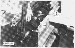
3. Fasten a nylon strap and a hoist on crankshaft (2), and put it in position in the cylinder block with the "C" marks on the camshaft drive gear and crankshaft drive gear in alignment.
NOTE: Install the bearings dry when the clearance checks are made. Put clean engine oil on all of the bearings for final assembly.
4. Check the main bearing clearances with Plastigage (A) as follows:
a. Put a piece of Plastigage (A) between the crankshaft and the main bearing.
NOTICE
Make sure the part number on the main bearing cap is toward the front of the engine and the number on the main bearing cap is the same as the number on the cylinder block on the left side of each main bearing cap.
NOTE: Do not turn the crankshaft when Plastigage (A) is in position.
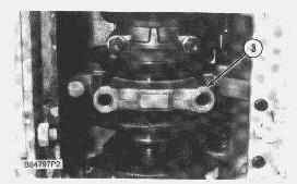
b. Install main bearing cap (3). Put 2P2506 Thread Lubricant on the bolt threads and the contact surfaces of the bolt heads. Install the bolts. Tighten the bolts on the side where the main bearing tabs are located, to a torque of 61 ± 6 N*m (45 ± 4 lb.ft.). Tighten the bolts on the opposite side to a torque of 61 ± 6 N*m (45 ± 4 lb.ft.).
c. Put a mark on each bolt head and the bearing caps. Turn the bolts that are opposite the main bearing tabs an extra 60° ± 5° from the mark. Turn the bolts on the side where the main bearing tabs are located an extra 60° ± 5° from the mark.
d. Remove main bearing caps (3), and measure the Plastigage. This will determine the bearing clearance. The main bearing clearance with a new bearing must be 0.076 to 0.168 mm (.0030 to .0066 in.). The maximum permissible clearance with used main bearings is 0.18 mm (.007 in.).
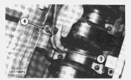
5. Put clean engine oil on thrust bearings (5) for the No. 3 main bearing saddle. Install a thrust bearing on each side of No. 3 main bearing saddle with the identification "BLOCK SIDE" toward the bearing saddle and the side with the oil grooves toward the crankshaft.
6. Install main bearing caps (3), and tighten the bolts as in steps 4b and 4c.
7. Put the clip and oil pickup tube support strip in position on the cylinder block as a unit, and install bolt (4) that holds them in place.
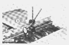
8. Check the end play of the crankshaft with tool (B). Be sure the dial indicator is against a machined surface. The end play is controlled by the thrust bearings on each side of No. 3 center main bearing. The end play with new bearings must be 0.064 to 0.480 mm (.0025 to .0189 in.). The maximum permissible end play with used bearings is 0.64 mm (.025 in.). Make a replacement of the thrust bearings if needed.
END BY:
a. install pistons and connecting rods
b. install flywheel housing
c. install timing gear cover
Product: INTEGRATED TOOLCARRIER
Model: IT12 INTEGRATED TOOLCARRIER 2YC
Configuration: IT12 INTEGRATED TOOLCARRIER 2YC00001-UP (MACHINE) POWERED BY 3204 ENGINE
Disassembly and Assembly
3204 VEHICULAR ENGINES
Media Number -SENR3230-00
Publication Date -01/10/1985 Date Updated -06/05/2020
Crankshaft Front Seal
SMCS - 1160-011; 1160-012
Remove Crankshaft Front Seal
START BY:
a. remove crankshaft pulley
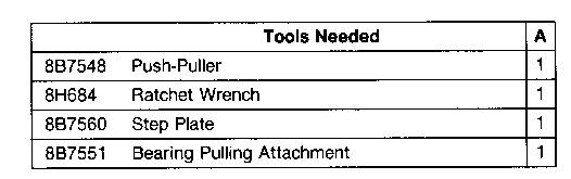
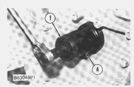
1. Use tooling (A) to remove crankshaft front seal (1) from the timing gear cover.
Install Crankshaft Front Seal
SENR32300002
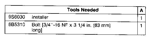
NOTE: If the crankshaft front pulley has been worn by the seal, use the 9S6012 Spacer [part of tooling (A)] to push the seal farther into the timing gear cover. This will locate the seal on the seal surface of the crankshaft pulley where there is no wear. Put the spacer from tooling (A) between the seal and the flange of the 9S6030 Installer. If there is no wear on the crankshaft pulley, do not use the 9S6012 Spacer.
1. Put 7F2770 Cement on the outer metal surface of the front seal. Put the seal in position on the short end of the 9S6030 Installer. The lip of the seal must be toward the inside of the engine.
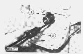
2. Put the seal and the 9S6030 Installer in position on the end of the crankshaft. Install washer (1) that is used to hold the crankshaft pulley and the 6S5310 Bolt. Tighten the bolt until the installer makes contact with the crankshaft gear. Remove tooling (A) and washer (1).
END BY:
a. install crankshaft pulley
Copyright 1993 - 2024 Caterpillar Inc. All Rights Reserved. Private Network For SIS Licensees. Mon Dec 30 23:34:26 UTC+0530 2024
Product: INTEGRATED TOOLCARRIER
Model: IT12 INTEGRATED TOOLCARRIER 2YC
Configuration: IT12 INTEGRATED TOOLCARRIER 2YC00001-UP (MACHINE) POWERED BY 3204 ENGINE
Disassembly and Assembly
3204 VEHICULAR ENGINES
Media Number -SENR3230-00
Publication Date -01/10/1985 Date Updated -06/05/2020
Crankshaft Main Bearings
SMCS - 1203-010
Remove And Install Crankshaft Main Bearings
START BY:
a. remove oil pan
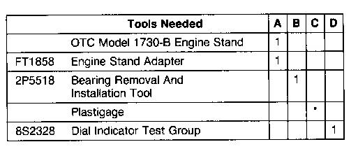
1. Put the engine on tooling (A).
SENR32300020
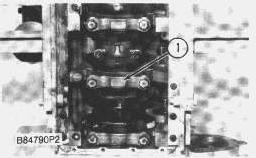
2. Remove the bolts that hold main bearing cap (1). Remove main bearing cap (1) and the lower half of the main bearing.
3. Remove the bearing from the cap.
NOTICE
If the crankshaft is turned in the wrong direction, the tab of the bearing will be pushed between the crankshaft and cylinder block. This can cause damage to either or both.
NOTE: The center and two end main journals have no oil hole. To remove these bearings, put a thin piece of soft material that will not damage the crankshaft journal against the end of the bearing opposite the tab. Hit the bearing with the soft material until the tab of the bearing is free from the groove in the cylinder block. Remove the upper half of the main bearing.
4. Remove the upper half of the other main bearings as follows:
a. Turn the crankshaft until tool (B) can be installed in the crankshaft journal. Install tool (B).
b. Turn the crankshaft in the direction which will push the upper main bearing out, tab end first.
c. Check the condition of the bearings. (See Guideline For Reusable Parts, Main And Connecting Rod Bearings, Form No. SEBF8009.)
5. Remove crankshaft thrust bearings (2) from each side of the No. 3 main bearing saddle.
NOTE: Install the main bearings dry when the clearance checks are made. Put clean engine oil on the main bearings for final assembly. Also, be sure the tabs on the back side of the main bearings fit in the grooves of the main bearing caps and cylinder block.
6. Clean the surfaces in the cylinder block for the main bearings. Use tool (B), and install new upper halves of main bearings (bearings with the oil hole) in the cylinder block. Do not put oil on the bearing.
7. Clean the surfaces of the main bearing caps for the main bearings. Install the new lower halves of the main bearings in the main caps without oil.
The serviceman must be very careful to use Plastigage correctly. The following points must be remembered:
...Make sure that the backs of the bearings and the bores are clean and dry.
...Make sure that the bearing locking tabs are properly seated in their slots.
...The crankshaft must be free of oil where the Plastigage touches it.
...If the main bearing clearances are checked with the engine upright or on its side, the crankshaft must be supported. Use a jack under an adjacent crankshaft counterweight and hold the crankshaft against the crown of the bearing. If the crankshaft is not supported, the weight of the crankshaft will cause incorrect readings.
...Put a piece of Plastigage on the crown of the bearing half that is in the cap. Do not allow the Plastigage to extend over the edge of the bearing.
...Install the bearing cap using the correct torque-turn specifications. Do not use an impact wrench. Be careful not to dislodge the bearing when the cap is installed.
...Do not turn the crankshaft with the Plastigage installed.
...Carefully remove the cap, but do not remove the Plastigage. Measure the width of the Plastigage while it is in the bearing cap or on the crankshaft journal. Do this by using the correct scale on the package. Record the measurements.
...Remove the Plastigage before installing the cap.
When using Plastigage, the readings can sometimes be unclear. For example, all parts of the Plastigage are not the same width. Measure the major widths to make sure that they are within the specification range. Also, experience has shown that when checking clearances tighter than 0.10 mm (.004") the readings may be low by 0.013 to 0.025 mm (.0005 to .0010"). Out-of-round journals can give faulty readings. Also, journal taper may be indicated when one end of the Plastigage is wider than the other.
Typical Example
For complete details concerning measuring bearing clearances, see Engine Bearings And Crankshafts, Form No. SEBD0531.
8. Check the main bearing clearance with Plastigage (C) as follows:
a. Put a piece of Plastigage (C) on the crown of the bearing half that is in the cap or on the crankshaft journal as shown.
NOTICE
Make sure the part number on the main bearing caps is toward the front of the engine and the number on the main bearing caps is the same as the number on the outside (camshaft side) of the cylinder block.
b. Put main bearing caps (1) in position on the cylinder block. Put 2P2506 Thread Lubricant on the bolt threads and the contact surfaces of the bolt heads, and install the bolts. Tighten the bolts on the side where the main bearing tabs are located to a torque of 61 ± 6 N·m (45 ± 4 lb.ft.). Tighten the bolts on the opposite side to a torque of 61 ± 6 N·m (45 ± 4 lb.ft.).
c. Put a mark on each bolt head and the bearing caps. Turn the bolts that are opposite the main bearing tabs an extra 60° ± 5° from the mark. Turn the bolts on the side where the main bearing tabs are located an extra 60° ± 5° from the mark.
d. Remove main bearing caps (1), and measure the Plastigage. This will determine the bearing clearance. The main bearing clearance with a new bearing must be 0.076 to 0.168 mm (.0030 to .0066 in.). The maximum permissible clearance with used main bearings is 0.18 mm (.007 in.).
9. Put clean engine oil on thrust bearings (2) from the No. 3 main bearing saddle. Install a thrust bearing on each side of No. 3 main bearing saddle with the identification "BLOCK SIDE" toward the bearing saddle and the side with the oil grooves toward the crankshaft.
10. Install main bearing caps (1), and tighten the bolts as in Steps 8b and 8c.
11. Check the end play of the crankshaft with tool (D). Be sure the dial indicator is against a machined surface. The end play is controlled by the thrust bearings on each side of No. 3 center main bearing. The end play with new bearings must be 0.064 to 0.480 mm (.0025 to .0189 in.). The maximum permissible end play with used bearings is 0.64 mm (.025 in.). Make a replacement of the thrust bearings if needed.
END BY:
a. install oil pan
Copyright 1993 - 2024 Caterpillar Inc. All Rights Reserved. Private Network For SIS Licensees.
Product: INTEGRATED TOOLCARRIER
Model: IT12 INTEGRATED TOOLCARRIER 2YC
Configuration: IT12 INTEGRATED TOOLCARRIER 2YC00001-UP (MACHINE) POWERED BY 3204 ENGINE
Disassembly and Assembly
3204 VEHICULAR ENGINES
Media Number -SENR3230-00
Publication Date -01/10/1985
Crankshaft Rear Seal and Wear Sleeve
SMCS - 1161-012; 1161-011
Remove Crankshaft
Date Updated -06/05/2020
SENR32300023
Rear Seal And Wear Sleeve
START BY:
a. remove flywheel
NOTE: Whenever the crankshaft seal is removed from the wear sleeve, a new Wear Sleeve and Seal Group must be installed as a set. If the seal is put back on the wear sleeve, the seal can be damaged.
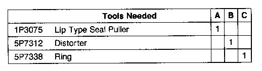
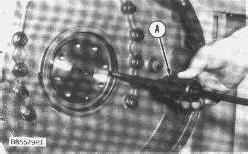
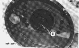
1. Remove the crankshaft rear seal with tool (A).
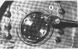
2. Install tool (C) in the rear seal bore.
3. Install tool (B) between tool (C) and the wear sleeve. Turn tool (B) until the edge of the tool makes a flat place (crease) in the wear sleeve. Do this in two or more places until the wear sleeve is loose.
4. Remove tool (C) and the wear sleeve by hand.
Install Crankshaft Rear Seal And Wear Sleeve
NOTICE
If the crankshaft rear seal and wear sleeve come apart during installation, the seal and wear sleeve become scrap. A new seal and wear sleeve must be installed as a set.
NOTE: The correct lubricant is on the new wear sleeve and seal group and no additional lubricant is necessary.
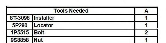
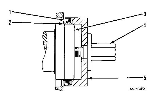
1. Install the crankshaft rear seal and wear sleeve with tooling (A) as follows:
a. Clean and prepare the crankshaft outside diameter with 6V1541 Quick Cure Primer. Apply 9S3265 Retaining Compound to the crankshaft outside diameter.
b. Install locator (3) and the bolts on the rear of the crankshaft.
c. Put wear sleeve (2) and seal (1) as a unit on locator (3) with the lip of the seal toward the front of the engine.
d. Put installer (5) in position on the locator.
e. Put clean engine oil on the face of nut (4), and install it on the locator. Tighten the nut until installer (5) makes contact with locator (3). Remove tooling (A).
END BY:
a. install flywheel
This is the sample of the manual click on the download link for complete manual