

G379 GAS ENGINE

Note: Use Bookmarks panel to navigate

Product: GAS ENGINE
Model: G379 GAS ENGINE 72B
Configuration: G379 ENGINE 72B00468-UP
Disassembly and Assembly
6.25" BORE ENGINE ATTACHMENTS
1N9318 & 7L135 Governor Air Actuators
SMCS - 4453-11; 4453-12
Disassemble Air Actuator
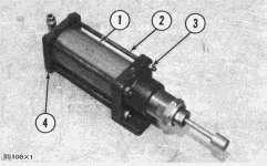
1. Remove the nuts (3) and bolts (2).
2. Remove the actuator end plate (4) and tube (1).
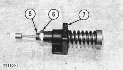
3. Remove the adjusting nut (6) and remove the plunger assembly (5) from the cover (7).
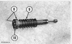
4. Remove the spring (9), two plates (8), and cup (10) from the plunger assembly.
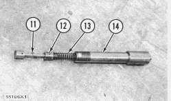
5. Push the rod assembly (12) into the plunger (14) and remove the ring (11).
6. Remove the rod assembly (12) and spring (13) from the plunger (14).
Assemble Air Actuator
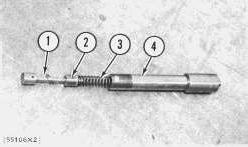
1. Install the spring (3), rod assembly (2) and ring (1) into the plunger (4).
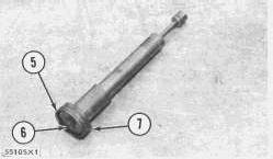
2. Install the plates (7), cup (5) and bolt (6) on the plunger assembly.
3. Put 4S9416 Anti-Seize Compound on the inside of the tube and on the plunger assembly.
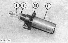
4. Install the plunger assembly (8) and spring into the tube (11).
5. Install the cover (10) on the plunger assembly. Install the adjusting nut (9).
This is the sample of the manual click on the download link for complete manual
DOWNLOAD LINK
For some reason if link does not work download this pdf and then click
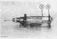
6. Install the actuator end plate (13) and nuts and bolts (12).
7. Turn adjusting nut (9) until plunger assembly starts to move, when inlet air pressure is 15 psi (1,0 kg/cm2).
Copyright 1993 - 2024 Caterpillar Inc. All Rights Reserved. Private Network For SIS Licensees.
Wed Jun 5 22:50:15 UTC+0530 2024
Product: GAS ENGINE
Model: G379 GAS ENGINE 72B
Configuration: G379 ENGINE 72B00468-UP
Disassembly and Assembly
6.25" BORE ENGINE ATTACHMENTS Media
2N6006 Governor Air Actuator
SMCS - 4453-11; 4453-12
Remove Diaphragm
NOTE: Diaphragm can be removed while actuator is on engine. Actuator adjustment is not changed by removing diaphragm.
1. Close air valve at tank and remove air line from actuator.
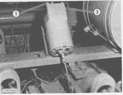
2. Remove bolts (1) slowly until tension is removed from spring.
3. Remove housing (2) from actuator.
4. Remove nuts holding guide (3) and diaphragm (4).
5. Remove guide (3) diaphragm (4) and clamp (5) from clamp (6).
6. Remove nuts holding clamp (6) in housing (2) and remove clamp from housing.
7. Inspect diaphragm for wear and cracks. Replace if necessary.
Install Diaphragm
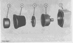
1. Install clamp (6) in housing.
2. Put liquid soap on diaphragm to make installation easier.
3. Install clamps (5), diaphragm (4) and guide (3) in clamp (6).
4. Install housing on actuator.
5. Install air line on actuator and open air valve.
6. Check for air leaks.
Remove Air Actuator
1. Close air valve at tank and remove air line from actuator.
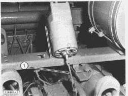
2. Remove linkage (1) between actuator and governor.
3. Remove actuator.
Install Air Actuator
1. Install actuator.
2. Install linkage between actuator and open air valve.
3. Install air line on actuator and open air valve.
Disassemble Air Actuator
start by:
a) remove air actuator
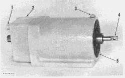
1. Remove rod (4).
2. Turn screw (3) out until nut (5) can be turned.
3. Turn nut out until tension is removed from spring.
4. Remove bolts (1) and remove housing (2). See topic REMOVE DIAPHRAGM.
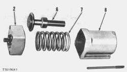
5. Remove nut, plunger (6) and spring (7) from housing (8).
6. Remove ring (11), spacer (10) and spring (9) from plunger (6).
Assemble Air Actuator
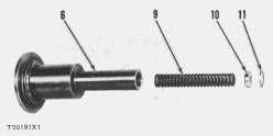
1. Install spring (9), spacer (10) and ring (11) in plunger (6).
2. Install spring (7), plunger (6) and nut (5) in housing (8).
3. Install housing (2).
4. Install rod (4). end by:
a) install air actuator
NOTE: See TESTING AND ADJUSTING to make adjustments to air pressure, low idle and high idle stops.
Copyright 1993 - 2024 Caterpillar Inc. All Rights Reserved. Private Network For SIS Licensees.
Wed Jun 5 22:49:51 UTC+0530 2024
Product: GAS ENGINE
Model: G379 GAS ENGINE 72B
Configuration: G379 ENGINE 72B00468-UP
Disassembly and Assembly
6.25" BORE ENGINE ATTACHMENTS Media
2N6961 Clutch Assembly
SMCS - 4453-11; 4453-12
Remove Clutch Assembly
NOTE: Disassembly and Assembly of the 2N7080 and 7L7490 Clutch Assemblies is similar to the 2N6961 Disassembly and Assembly.
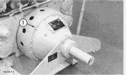
1. Remove all but one of the clutch assembly mounting bolts (1).
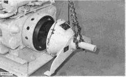
2. Attach hoist to the clutch assembly as shown.
3. Remove the remaining mounting bolt and remove clutch assembly from the engine. Weight is 330 lbs. (150 kg).
Install Clutch Assembly
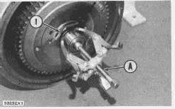
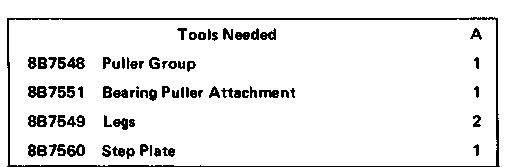
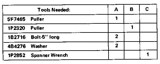
1. Using tool setup (A) remove the pilot bearing from the shaft.
2. Using tool setup (B) remove the hub retaining nut (1) and lock.
3. Install the nut on the shaft with about half of the threads engaged.
4. Remove clutch assembly inspection cover.
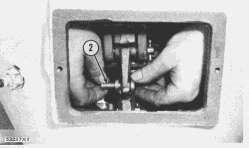
5. Remove the four link pins (2).
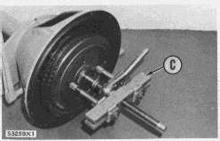
6. Using tool setup (C) pull the hub free from the shaft.
7. Remove the clutch disc and hub assembly. Weight is 110 lbs. (50 kg.)
8. Remove the key from the shaft.
Install Clutch Disc And Hub Assembly
1. Install the key in the shaft.
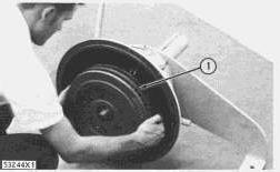
2. Install the clutch disc and hub assembly (1).
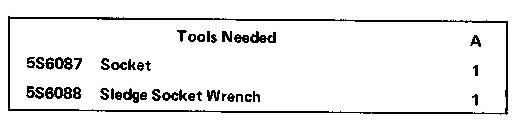
3. Install the hub nut and lock using tool (A).
4. See TESTING AND ADJUSTING for torque of hub nut.
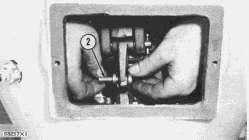
5. Install the four link pins (2).
6. Install the inspection cover.
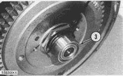
7. Install the pilot bearing (3) on the shaft. end by:
a) install clutch assembly
Disassemble Clutch Disc And Hub Assembly
start by:
a) remove clutch disc and hub assembly
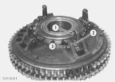
1. Remove the lever pins (3), levers (1), and spring washers (2).
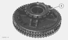
2. Push down the lock pin and remove the adjustment ring (4).
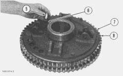
3. Remove the lock pin (5) and spring (6).
4. Remove the floating plate (7) and a clutch disc (8).
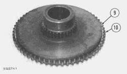
5. Remove the center plate (9) and remaining clutch disc (10) from the hub.
Assemble Clutch Disc And Hub Assembly
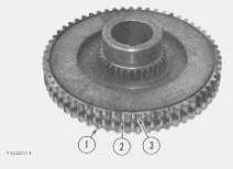
1. Install the clutch disc (1), center plate (2) and clutch disc (3) on the hub.
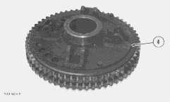
2. Install the floating plate (4).
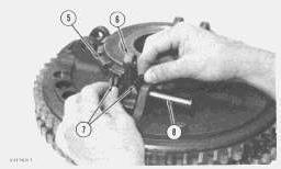
3. Install the spring, locking pin, and adjustment ring (5).
4. Install the levers (6), spring washers (7) and pins (8).
end by:
a) install clutch disc and hub assembly
Remove Collar And Sliding Sleeve
start by:
a) remove clutch disc and hub assembly
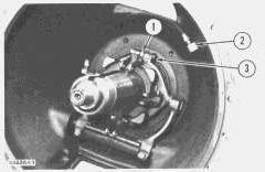
1. Disconnect the grease fitting (2) from the clutch housing.
2. Remove the two collar bolts (3) and spacers (1).
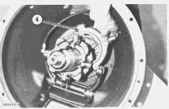
3. Move the clutch control lever forward until the collar (4) can be removed fron the sliding sleeve.
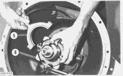
4. Remove the other half of the collar (5) and remove the sliding sleeve (6).
Install Collar And Sliding Sleeve
1. Install the sliding sleeve on the shaft.
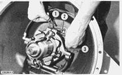
2. Install the collar (3), collar bolts (2) and spacers (1).
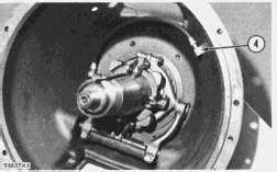
3. Connect the grease fitting (4) to the housing.
4. Fill the collar and sliding sleeve with grease until grease can be seen between the sliding sleeve and shaft.
end by:
a) install clutch disc and hub assembly
Remove Shaft And Bearings
start by:
a) remove collar and sliding sleeve
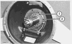
1. Remove the bearing retainer lock (1) and remove the bearing retainer (2).
2. Hit the output end of the shaft until the bearing inner cup can be removed.
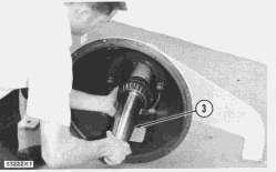
3. Remove the shaft (3) from the housing. Weight is 75 lbs. (32 kg).
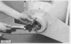
4. Remove the bearing outer cup from the housing as shown.
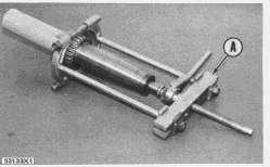
5. Using tool setup (A), remove the bearing cones from the shaft.
Install Shaft And Bearings
1. The temperature of the bearings must be 275° F (135° C) when they are installed on the shaft.
2. Install the bearing outer cup in the clutch housing.
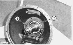
3. Install the shaft (1) and bearing inner cup (2).
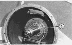
4. Install the bearing retainer (3). Tighten the retainer lightly until there is no clearance between the bearing cup and the bearing cone.
5. See TESTING AND ADJUSTING for end clearance of shaft.
6. Install lock. end by:
a) install collar and sliding sleeve
1993 - 2024 Caterpillar Inc.
Network For SIS Licensees. Wed Jun 5 22:50:35 UTC+0530 2024
Product: GAS ENGINE
Model: G379 GAS ENGINE 72B
Configuration: G379 ENGINE 72B00468-UP
Disassembly and Assembly
6.25" BORE ENGINE ATTACHMENTS
Air Starting Motor
SMCS - 4453-11; 4453-12
Remove Air Starting Motor
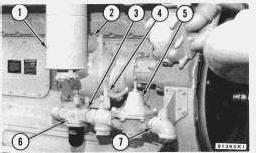
1. Close the outlet valve on the air tank and remove air line between the air tank and the pressure regulating valve (5).
2. Remove exhaust elbow (2) and silencer (1).
3. Remove inlet elbow bolts (3) and U-bolt (7).
4. Remove pressure regulating valve (5), balanced whistle valve (4), oiler (6) and inlet elbow as a unit.
5. Install a 1/2"-13 NC forged eyebolt and install hoist.
6. Remove air starting motor. Weight is 82 lbs. (37,2 kg).
Install Air Starting Motor
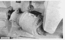
1. Install air starting motor.
2. Install pressure regulating valve (5), balanced whistle valve (4), oiler (6) and inlet elbow as a unit.
3. Install exhaust elbow (2) and silencer (1).
4. Install air line between the pressure regulating valve and the air tank.
5. Open the outlet valve on the air tank.
Disassemble Air Starting Motor
start by:
a) remove air starting motor
1. Put marks on parts to make alignment during assembly easier.
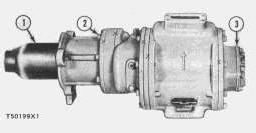
2. Remove bolts (2) and remove drive housing (1).
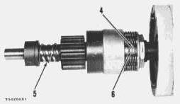
3. Remove ring (4) and screw (6).
4. Remove drive (5).
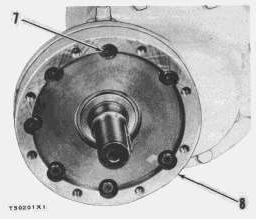
7.
8.
9.
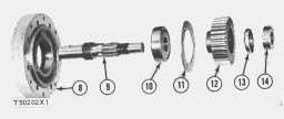
5. Remove socket head screws (7) and remove cover (8).
6. Bend lockwasher (13) and remove nut (14) using tool (C).
Remove gear (12).
Remove retainer (11) and push shaft (9) out of bearing (10).
Push bearing (10) out of cover (8).
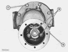
10. Remove bolts (17) and (18) and remove gear housing (19).
11. Remove cover (3).
12. Bend lockwasher and remove nut using tool (C).
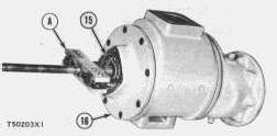
13. Remove plate assembly (16) and bearing (15) using tool setup (A).
14. Remove air motor housing.
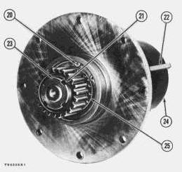
15. Remove vanes (22) from rotor (24).
16. Bend lockwasher (21) and remove nut (23) using tool (C).
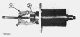
17. Remove gear (26) using tool (B).
18. Remove ring (20) and bearing (25).
Assemble Air Starting Motor
See AIR STARTING MOTOR, TESTING AND ADJUSTING to make rotor clearance adjustment.
NOTE: Assemble parts with marks in alignment.
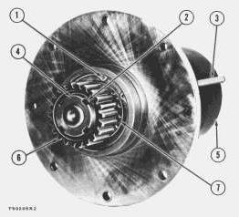
1. Install bearing (7) and ring (1).
2. Install gear (6), lockwasher (2) and nut (4).
3. Install vanes (3) into rotor (5).
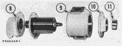
4. Install air motor housing (9).
5. Install gear housing (8).
6. Install plate assembly (10) and bearing (11).
7. Install lockwasher and nut.
8. Install cover.
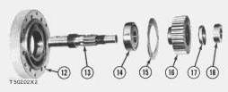
9. Install bearing (14) in cover (12).
10. Install shaft (13) and retainer (15).
11. Install gear (16), lockwasher (17) and nut (18).
12. Install cover (12) onto gear housing (8).
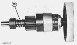
13. Install drive (19).
14. Install drive housing. end by:
a) install air starting motor
Copyright 1993 - 2024 Caterpillar Inc.
All Rights Reserved.
Private Network For SIS Licensees.
Wed Jun 5 22:51:27 UTC+0530 2024
Product: GAS ENGINE
Model: G379 GAS ENGINE 72B
Configuration: G379 ENGINE 72B00468-UP
Disassembly and Assembly
6.25" BORE ENGINE ATTACHMENTS
Media Number -REG01084-01
Flexible Coupling
SMCS - 4453-11; 4453-12
Disassemble Flexible Coupling
1. Remove guard from around the coupling.
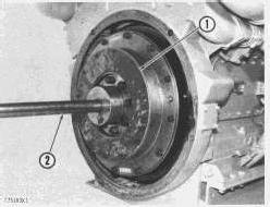
2. Remove plate (1) and gasket (4) from coupling and let them rest on drive shaft (2).
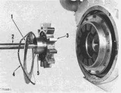
3. Separate shaft (2) and driven coupling (3) from engine.
4. Hub (5) is a press fit on shaft (2) and is secured by a key. Press hub off shaft.
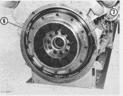
5. Remove drive coupling (6) from flywheel (7).
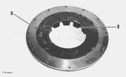
6. Remove plate (8), hub (9) and gasket from drive coupling.
Assemble Flexible Coupling
8S2328 Dial Test Indicator Group
1. Clean all parts thoroughly.
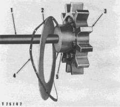
2. Install key into keyway of drive shaft (1).
3. Align the key slot in hub (5) with the key in the drive shaft and press the hub onto the drive shaft. The hub can be heated to facilitate installation.
4. Place plate (2) and gasket (4) over hub (5) and onto the drive shaft.
5. Install driven coupling (3) onto the hub.
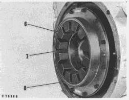
6. Install the gasket and plate on the flange side of drive coupling (8).
7. Install coupling (8) onto the engine flywheel.
8. Place boot (6) over the teeth of drive coupling.
9. Apply 4L7464 Silicone Grease on the teeth and cavities (7) of the boot.
10. Move the engine or the driven equipment, depending upon the installation, until the driven coupling is fully engaged with the drive coupling.
11. Fill the void between boot (6) and the driven coupling with silicone grease.
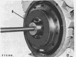
12. Install gasket and plate (9).
13. Make certain the drive coupling is centered between plates (2) and (9), so as not to restrict the engine crankshaft end clearance.
14. Clearance between plates (2) and (9) is .009 in. (0,23 mm).
This is the sample of the manual click on the download link for complete manual
DOWNLOAD LINK
For some reason if link does not work download this pdf and then click