


Product: GAS ENGINE
Model: G3516B GAS ENGINE N6E
Configuration: G3516B Gas Engine N6E00001-UP
Disassembly and Assembly
G3508B, G3512B, G3512B, G3516B and G3520B Petroleum Engines
Media Number -KENR8147-06 Publication Date -01/03/2015 Date Updated -25/10/2017
Accessory Drive (Front) - Assemble
SMCS - 1207-016
Assembly Procedure Table 1 Required Tools
NOTICE
Keep all parts clean from contaminants.
Contaminants may cause rapid wear and shortened component life.
i06749290
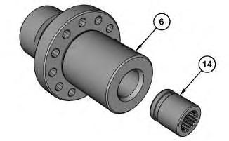
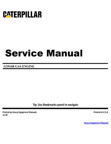
Illustration 1
1. Use Tooling (A) and a suitable press to install bushing (14) into shaft (6). Bushing (14) must be installed flush with shaft (6), with a tolerance of ± 0.5 mm (0.020 inch)
Note: With shaft (6) fixed, bushing (14) must not slip when apply 271 N·m (200 lb ft) of torque to the bushing.

Illustration 2
g01255150
2. Align the oil hole in the bearing and the oil hole in front adapter assembly (9). Use Tooling (A) and a suitable press to install bearing (11) into front adapter assembly (9). The bore of the bearing must be 75.0 ± 0.055 mm (2.95 ± 0.0020 inch) after installation.
3. Install O-ring seals (12) and (13) into front adapter assembly (9).

3 g01255149
4. Place clean engine oil on the bearing and install shaft (6) in front adapter assembly (9).
5. Install retaining washer (10) and the bolts.
Note: Later models have two retaining washers.

Illustration 4
g01255146
6. Position gear (8) on shaft (6) and install bolts (7).

Illustration 5
g01255143
7. Align the oil hole in the bearing and the oil hole in rear adapter assembly (1). Use Tooling (A) and a suitable press to install bearing (5) into rear adapter assembly (1). The bore of the bearing must be 75.0 ± 0.055 mm (2.95 ± 0.0020 inch) after installation.
8. Use Tooling (B) to install seal (4) into rear adapter assembly (1). Ensure that the lip of the seal is toward the bearing.

Illustration 6
g00906726
9. Install O-ring seals (2) and (3) into rear adapter assembly (1). Place clean engine oil on the O-ring seals.
End By:
a. Install the accessory drive (front). Refer to Disassembly and Assembly, "Accessory Drive (Front) - Install".
Fri Jul 30 10:41:30 UTC+0530 2021
Product: GAS ENGINE
Model: G3516B GAS ENGINE N6E
Configuration: G3516B Gas Engine N6E00001-UP
Disassembly and Assembly
G3508B, G3512B, G3512B, G3516B and G3520B Petroleum Engines
Media Number -KENR8147-06 Publication Date -01/03/2015 Date Updated -25/10/2017
Accessory Drive (Front) - Disassemble
SMCS - 1207-015
Disassembly Procedure Table 1
Required Tools Tool Part Number Part
A 1P-0520 Driver Group 1
Start By:
a. Remove the accessory drive (front). Refer to Disassembly and Assembly, "Accessory Drive (Front) - Remove".
NOTICE
Keep all parts clean from contaminants.
Contaminants may cause rapid wear and shortened component life.

Illustration 1
g00906726
1. Remove O-ring seals (2) and (3) from rear adapter assembly (1).
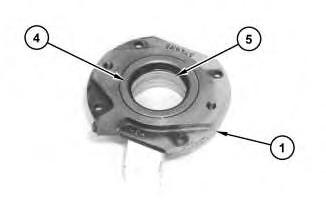
Illustration 2
g01255143
2. Remove seal (4) from rear adapter assembly (1).
3. Use Tooling (A) and a suitable press to remove bearing (5) from rear adapter assembly (1).

Illustration 3
g01255146
4. Remove bolts (7) and gear (8) from shaft (6).
Illustration 4
g01255149
5. Remove the bolts and retaining washer (10).
Note: Later models have two retaining washers.
6. Remove shaft (6) from front adapter assembly (9).

Illustration 5
g01255150
7. Remove O-ring seals (12) and (13) from front adapter assembly (9).
8. Use Tooling (A) and a suitable press to remove bearing (11) from front adapter assembly (9).

9. Remove bushing (14) from shaft (6).
Copyright 1993 - 2021 Caterpillar Inc. All Rights Reserved. Private Network For SIS Licensees. Fri Jul 30 10:41:11 UTC+0530 2021
Product: GAS ENGINE
Model: G3516B GAS ENGINE N6E
Configuration: G3516B Gas Engine N6E00001-UP
Disassembly and Assembly
G3508B, G3512B, G3512B, G3516B and G3520B Petroleum Engines
Media Number -KENR8147-06
Publication Date -01/03/2015
Accessory Drive (Front) - Install
SMCS - 1207-012
Installation Procedure NOTICE
Keep all parts clean from contaminants.
Date Updated -25/10/2017
Contaminants may cause rapid wear and shortened component life.


Illustration 1 g01351317
Typical example
1. Install shaft (11), thrust washers (10), and drive gear (9) as a unit.
Note: Ensure that the teeth of the accessory gear are correctly engaged with the teeth of the lower accessory drive gear.


Illustration 2 g01351316
Typical example
2. Place clean engine oil on the O-ring seals for front adapter assembly (7). Install front adapter assembly (7) and install bolts (8).
3. Install front cover (5), bolts (6), and the washers.

Illustration 3 g01351314
4. Place clean engine oil on the O-ring seals on rear adapter assembly (2) and on the bearing in rear adapter assembly (2). Install rear adapter assembly (2) and bolts (4).
5. Place clean engine oil on the O-ring seal. Install rear cover (1), bolts (3), and the washers.
Copyright 1993 - 2021 Caterpillar Inc. All Rights Reserved. Private Network For SIS Licensees. Fri Jul 30 10:41:49 UTC+0530 2021
Product: GAS ENGINE
Model: G3516B GAS ENGINE N6E
Configuration: G3516B Gas Engine N6E00001-UP
Disassembly and Assembly
G3508B, G3512B, G3512B, G3516B and G3520B Petroleum Engines
Media Number -KENR8147-06
Publication Date -01/03/2015 Date Updated -25/10/2017
Accessory Drive (Front) - Remove
SMCS - 1207-011
Removal Procedure Table 1 Required Tools
Keep all parts clean from contaminants.
Contaminants may cause rapid wear and shortened component life.
Illustration 1 g01351314
Typical example
1. Remove bolts (3) and the washers. Remove rear cover (1) with the O-ring seals.
2. Remove bolts (4) and use Tooling (A) to remove rear adapter assembly (2).
Illustration 2 g01351316
Typical example
3. Remove bolts (6) and the washers. Remove front cover (5).
4. Remove bolts (8) and use Tooling (A) to remove front adapter assembly (7).
Illustration 3 g01351317
5. Remove drive gear (9), thrust washers (10), and shaft (11) as a unit.
Copyright 1993 - 2021 Caterpillar Inc. All Rights Reserved. Private Network For SIS Licensees. Fri Jul 30 10:40:54 UTC+0530 2021
Product: GAS ENGINE
Model: G3516B GAS ENGINE N6E
Configuration: G3516B Gas Engine N6E00001-UP
Disassembly and Assembly
G3508B, G3512B, G3512B, G3516B and G3520B Petroleum Engines
Media Number -KENR8147-06 Publication Date -01/03/2015 Date Updated -25/10/2017
Accumulator - Assemble
SMCS - 1320-016
S/N - GLF1100-UP
S/N - JB31-UP
S/N - JBW1-UP
S/N - JEF1-UP
S/N - JHH1-UP
S/N - N2S1-UP
S/N - N6E1-UP
S/N - N8C1-UP
S/N - RBK1-UP
S/N - TPC140-140
S/N - TPC1002-1004
S/N - TPC1100-UP
Assemble
Table 1
Required Tools
i03451947
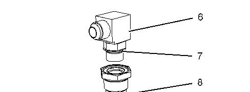


Illustration 1 g01796534
Personal injury can result from parts and/or covers under spring pressure.
Spring force will be released when covers are removed.
Be prepared to hold spring loaded covers as the bolts are loosened.
1. Position ball (10) and spring (9) into adapter (12).
2. If necessary, replace O-ring seal (11). Install plug (8).
3. If necessary, replace O-ring seal (7). Position O-ring seal (7) on elbow (6) and install elbow (6).


Illustration 2 g01796533
Dry nitrogen is the only gas approved for use in the accumulators. The charging of oxygen gas in an accumulator will cause an explosion. An explosion can be eliminated by using nitrogen gas cylinders with standard CGA (Compressed Gas Association, Inc.) No. 580 connectors. When nitrogen gas is ordered, make sure to order the cylinders with CGA No. 580 connectors.
Do not rely on color codes or other methods of identification to tell the difference between nitrogen and oxygen cylinders. In any application, never use an adapter to connect your nitrogen charging group to a valve outlet used on both nitrogen, oxygen, or other gas cylinders. BE SURE YOU USE DRY NITROGEN (99.8% purity).
4. Use engine oil to lubricate the inside of accumulator assembly (1). Install the piston with the seals in accumulator assembly (1) and lubricate the inside of accumulator with engine oil. Use Tooling (A) to assembly.
5. Accumulator assembly (1) will need to be refilled with gas. Refer to Operation and Maintenance Manual, "Accumulator - Check".
6. Position accumulator assembly (1) on plate (4).
7. Install the washers and bolts (5). Close strap assembly (3).
8. Install the spacer, the washer, and bolt (2). Copyright 1993 - 2021 Caterpillar Inc. All Rights Reserved.
Network For SIS Licensees. Fri Jul 30 10:25:47 UTC+0530 2021
Product: GAS ENGINE
Model: G3516B GAS ENGINE N6E
Configuration: G3516B Gas Engine N6E00001-UP
Disassembly and Assembly
G3508B, G3512B, G3512B, G3516B and G3520B Petroleum Engines
Media Number -KENR8147-06 Publication Date -01/03/2015 Date Updated -25/10/2017
Accumulator - Disassemble
SMCS - 1320-015
S/N - GLF1100-UP
S/N - JB31-UP
S/N - JBW1-UP
S/N - JEF1-UP
S/N - JHH1-UP
S/N - N2S1-UP
S/N - N6E1-UP
S/N - N8C1-UP
S/N - RBK1-UP
S/N - TPC140-140
S/N - TPC1002-1004
S/N - TPC1100-UP
Disassembly Procedure
Table 1
Required Tools
i03451160
Dry nitrogen is the only gas approved for use in the accumulators. The charging of oxygen gas in an accumulator will cause an explosion. An explosion can be eliminated by using nitrogen gas cylinders with standard CGA (Compressed Gas Association, Inc.) No. 580 connectors. When nitrogen gas is ordered, make sure to order the cylinders with CGA No. 580 connectors.
Do not rely on color codes or other methods of identification to tell the difference between nitrogen and oxygen cylinders. In any application, never use an adapter to connect your nitrogen charging group to a valve outlet used on both nitrogen, oxygen, or other gas cylinders. BE SURE YOU USE DRY NITROGEN (99.8% purity).
1. Remove gas pressure from the accumulator assembly. Refer to Operation and Maintenance Manual, "Accumulator - Check".


Illustration 1 g01796533
2. Remove bolt (2), the washer, and the spacer.