


Note: Use Bookmarks panel to navigate
This is the sample of the manual click on the download link for complete manual
DOWNLOAD LINK
For some reason if link does not work download this pdf and then click

Product: GAS ENGINE
Model: G3512E GAS ENGINE NWC
Configuration: G3512E Generator Set NWC00001-UP
Disassembly and Assembly
G3512E, G3516C and G3516E Generator Set Engines
Media Number -KENR5271-12 Publication Date -01/05/2020
Accessory Drive (Front) - Assemble
SMCS - 1207-016
Assembly Procedure
Updated -27/05/2020

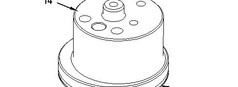

1. Install O-ring seal (15) onto idler shaft (14).

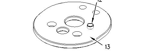

Illustration 2 g00993345
2. Install dowel (12) into washer (13).
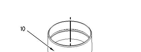
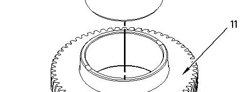

Illustration 3 g00993344
3. Lower the temperature of bearing (10).
4. Install bearing (10) into gear (11).
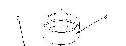
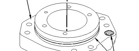

Illustration 4 g00993343
5. Install O-ring seals (9) into adapter assembly (7).
6. Lower the temperature of bearing (8).
7. Install bearing (8) into adapter assembly (7).
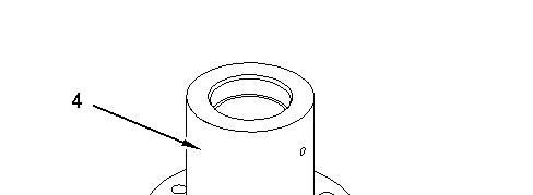
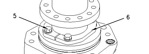

Illustration 5 g00993342
8. Install auxiliary drive shaft (4) into adapter assembly (7).
9. Position thrust washers (6).
10. Install bolts (5).
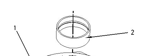
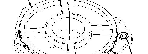

Illustration 6 g00993341
11. Lower the temperature of bearing (2).
12. Install bearing (2).
13. Install O-ring seals (3) into adapter assembly (1).
End By:
a. Install the accessory drive. Refer to Disassembly and Assembly, "Accessory Drive (Front)Install".
Copyright 1993 - 2024 Caterpillar Inc. All Rights Reserved. Private Network For SIS Licensees. Wed Feb 14 00:16:43 UTC+0530 2024
Product: GAS ENGINE
Model: G3512E GAS ENGINE NWC
Configuration: G3512E Generator Set NWC00001-UP
Disassembly and Assembly
G3512E, G3516C and G3516E Generator Set Engines
Media Number -KENR5271-12
Accessory Drive (Front) - Disassemble
SMCS - 1207-015
Disassembly Procedure Table 1
Tools
Start By:
a. Remove the accessory drive. Refer to Disassembly and Assembly, "Accessory Drive (Front) - Remove".
Illustration 1 g00993341
1. Remove O-ring seals (3) from adapter assembly (1).
2. Use Tooling (A) in order to remove bearing (2) from adapter assembly (1).
Illustration 2 g00993342
3. Remove bolts (5).
4. Remove thrust washers (6).
5. Remove auxiliary drive shaft (4) from adapter assembly (7).
Illustration 3 g00993343
6. Remove O-ring seals (9) from adapter assembly (7).
7. Use Tooling (A) in order to remove bearing (8).
Illustration 4 g00993344
8. Use Tooling (A) in order to remove bearing (10) from gear (11).
Illustration 5 g00993345
9. Remove dowel (12) from washer (13).
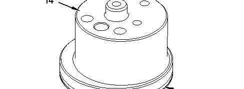

Illustration 6 g00993346
10. Remove O-ring seal (15) from idler shaft (14).
Copyright 1993 - 2024 Caterpillar Inc. All Rights Reserved. Private Network For SIS Licensees.
Wed Feb 14 00:14:41 UTC+0530 2024
Product: GAS ENGINE
Model: G3512E GAS ENGINE NWC
Configuration: G3512E Generator Set NWC00001-UP
Disassembly and Assembly
G3512E, G3516C and G3516E Generator Set Engines
Media Number -KENR5271-12
Accessory Drive (Front) - Install
SMCS - 1207-012
Installation Procedure Illustration 1
-01/05/2020
Updated -27/05/2020
i01883682
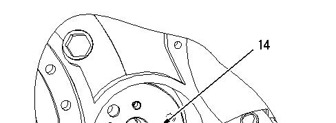
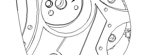

1. Position washer assembly (14).
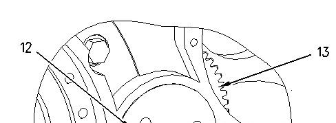
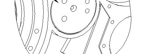

Illustration 2 g00993340
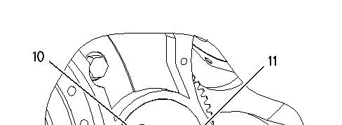
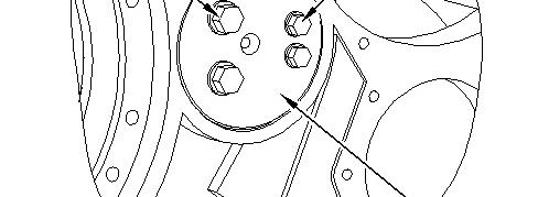

Illustration 3 g00993337
3. Install bolts (10) and bolts (11) into idler shaft (12).
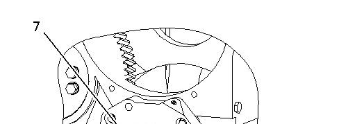
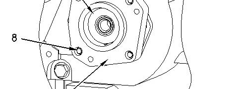

Illustration 4 g00993336
4. Install adapter assembly (9) and the O-ring seals. Auxiliary drive shaft (7) is attached to adapter assembly.
5. Install bolts (8).
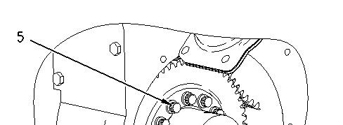
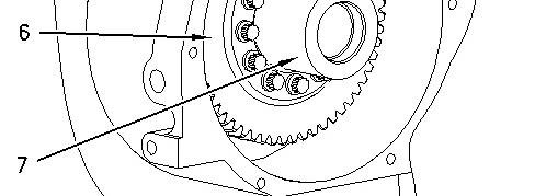

Illustration 5 g00993335
6. Position gear (6) onto auxiliary drive shaft (7).
7. Install bolts (5).
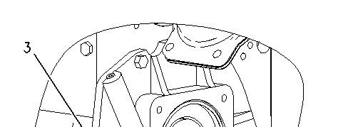
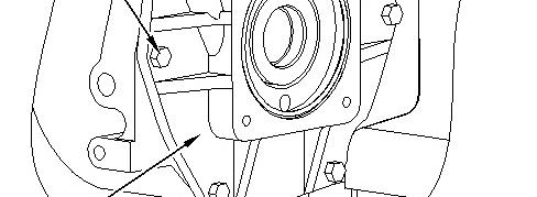

Illustration 6 g00993334
8. Position adapter assembly (4).
9. Install bolts (3).
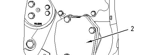

10. Position the gasket. Install cover (2).
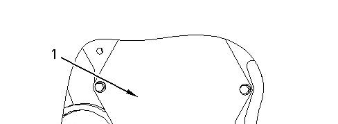
11. Position the O-ring seals. Install cover (1).
End By:
a. Install the vibration damper. Refer to Disassembly and Assembly, "Vibration DamperRemove and Install".
b. Install the auxiliary water pump. Refer to Disassembly and Assembly, "Auxillary Water Pump - Install".
Product: GAS ENGINE
Model: G3512E GAS ENGINE NWC
Configuration: G3512E Generator Set NWC00001-UP
Disassembly and Assembly
G3512E, G3516C and G3516E Generator Set Engines
Accessory Drive (Front) - Remove
SMCS - 1207-011
Removal Procedure
Table 1
Required Tools
Start By:
a. Remove the auxiliary water pump. Refer to Disassembly and Assembly, "Auxillary Water Pump - Remove".
b. Remove the vibration damper. Refer to Disassembly and Assembly, "Vibration DamperRemove and Install".
Note: The vibration damper does not need to be removed if the idler gear does not need to be removed.
Illustration 1 g00993333
1. Remove cover (1) and the O-ring seals.
2. Remove cover (2) and the gasket.
Illustration 2 g00993334
3. Remove bolts (3).
4. Remove adapter assembly (4).
Illustration 3 g00993335
5. Remove bolts (5).
6. Remove gear (6) from auxiliary drive shaft (7).
This is the sample of the manual click on the download link for complete manual
DOWNLOAD LINK
For some reason if link does not work download this pdf and then click