DOWNLOAD LINK
For some reason if link does not work download this pdf and then click
Product: GAS ENGINE
Model: G342C GAS ENGINE 71B
Configuration: G342 ENGINE 71B00001-UP
Operation and Maintenance Manual
G342C NATURAL GAS ENGINE
Altitude Operation
SMCS - 1350; 1352; 1395; 7542-008
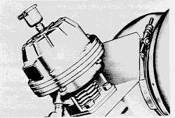
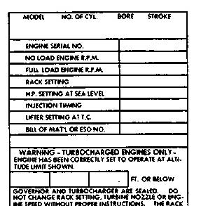
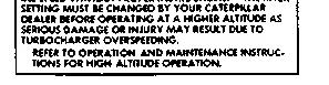
Turbocharger speed is determined by engine high idle speed, turbocharger nozzle, exhaust bypass valve regulator assembly, and the altitude at which the engine is operating. The altitude limits are stamped on the engine information plate. The regulator assembly is sealed and any changes to the regulator assembly should be made only by your Caterpillar dealer.
The engine can be operated safely at lower altitudes than specified on the engine information plate, but will not produce rated horsepower.
Always consult your Caterpillar dealer whenever changes in operating altitudes are anticipated which differ from the nameplate limits.
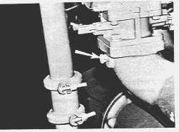
EXHAUST BYPASS VALVE
ENGINE INFORMATION PLATE
Copyright 1993 - 2024 Caterpillar Inc. All Rights Reserved. Private Network For SIS Licensees. Wed Dec 4 02:31:46 UTC+0530 2024
Product: GAS ENGINE
Model: G342C GAS ENGINE 71B
Configuration: G342 ENGINE 71B00001-UP
Operation
and Maintenance Manual
G342C NATURAL GAS ENGINE
Attachments
SMCS - 1350; 1352; 1395; 7542-008
Governor Controls
Various types of governor controls can be installed on engines according to the application. The most common control is direct mechanical. The control may be mounted either on the engine or on a remote control panel. Engine mounted controls normally consist of a positive locking handle connected directly to the governor shaft. Cables and vernier controls mount on the engine or on a control panel.
Shutdown controls are used only to stop the engine. Mechanical or electrical controls are commonly used. These devices stop the gas flow. Shutdown controls allow the engine to be restarted after shutdown without readjusting the speed controls. Shutdown controls are usually found on Automatic Start-Stop installations.
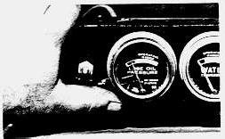
Gauges
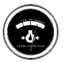
OIL PRESSURE
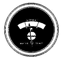
WATER TEMPERATURE
Gauges provide a "look" inside the engine. Be sure they are in good working order. You can determine what is "normal" operating range by observing the gauges over a period of time. The cause of any sudden or significant change in the readings should be determined and corrected.
OIL PRESSURE - Oil pressure is normally greatest when starting a cold engine. As the oil warms up it will produce less pressure. Oil pressure is greater at operating speeds than at low idle. Fluctuating readings can mean air in the oil or a sticking pressure relief valve. Stop the engine immediately if a sudden loss of oil pressure occurs.
WATER TEMPERATURE - The operating temperature is determined by the water temperature regulator. High coolant temperatures mean the cooling system is not dissipating enough engine heat. Pressurized cooling system gauges are marked with ranges rather than temperatures. If the gauge indicates in the red range, the cooling system should be inspected.
The minimum operating temperature should not be below the opening temperature of the water temperature regulator.
In cold weather the temperature gauge may fluctuate in or near the cold range. This indicates the engine is being overcooled. In these instances the use of radiator louvers is suggested.
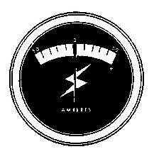
AMMETER - The ammeter should register in the charging range when the engine is running above low idle. If the gauge registers a discharge when the engine speed is increased, determine the cause.
Automatic Start-Stop
An automatic start-stop system ensures that power is supplied to a load when the normal power source is interrupted. The cranking panel is the heart of the system and consists of the failure warning system and relays to start and stop the engine. When a power failure occurs the system senses the failure and starts the engine to transfer the load to standby. When power is restored, it senses and transfers the load from standby and stops the engine. The major use of automatic start-stop systems is standby electric sets and this discussion is limited to that application.
If a power failure occurs, a circuit breaker opens and a set of contacts in the transfer switch closes, completing the circuit to the starter motor. When the engine starts, the starter circuit opens, protecting the starter from overspeed damage.
Since a standby engine is usually unmanned, it is usually protected from mechanical malfunction by a series of electrical safety devices: high water temperature, low oil pressure and engine overspeed. If a fault occurs it energizes one of the shut-off controls and grounds the magneto to stop the engine.
NOTICE
DO NOT use any emergency shut-off control for normal shut down. The emergency shut-off controls are for emergencies only.
If the unit has a standard cranking panel, the battery and starter are protected from prolonged cranking by a cranking cycle timer. A timer providing five ten-second cranking cycles can be used. Both units have fault lights which light if the cranking cycle is completed and the engine does not start.
Automatic start-stop units may have a time delay relay to prevent the standby circuit breaker from closing until the engine has had a few seconds warm up time. A shutdown time delay provides up to two minutes to cool off after the load has been transferred back to normal power source.
A time delay relay in the transfer circuit can be adjusted from 1 to 30 minutes. This delays the transfer from standby to normal power until the normal source has been restored and remained stable for the preset period.
Unattended units may have an exerciser. At a preset time the engine automatically starts and runs, under load if possible, and shuts itself off. This helps to ensure the until will start and perform as required when necessary.
A shutdown timer may also be used with an automatic start-stop system. This provides a two minute cool off period after the load has been removed from the engine. This allows the heat of full load operation to be dissipated gradually.
Many safety circuits have fault lights to aid the operator in locating the cause of the malfunction. These lights are lighted by the safety circuit that is energized by a mechanical fault i.e., high water temperature, low oil pressure, etc.
Safety Gauges
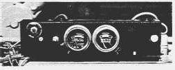
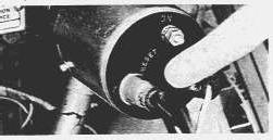
Safety shut-offs protect the engine from damage if conditions exceed normal operating limits. The safety circuits sense oil pressure and water temperature. The sending units are a part of the gauges in the instrument panels. If a fault occurs, the water temperature or oil pressure indicator will make contact with a terminal and completes the shutdown circuit. A magnetic switch is energized and grounds the magneto to stop the engine. Before restarting the engine, push the magnetic switch reset button, located on the instrument panel. The oil pressure switch reset button, located on the oil pressure gauge, must be held in during starting.
SAFETY GAUGES
A manual stop button located on the instrument panel should be used only in an emergency. The manual stop button grounds the magneto to stop the engine.
Unburned gas left in the manifold can ignite when the engine is restarted.
Before restarting any gas engine which was stopped by grounding the magneto, crank the engine with the gas valve turned off and the magneto grounded for 10-15 seconds. This will clear the unburned gas from the exhaust system.
Gas Shut-Off Valve
A gas shut-off valve is available. On an electrical signal from either the safety circuit or a remote mounted switch, the valve closes, stopping the gas flow to the engine. This valve must be reset manually.
Overspeed Switch
A contractor actuated by a flyweight governor provides overspeed protection for the engine. The overspeed switch is mounted on the tachometer drive. If the engine overspeeds, the governor closes
the contacts, energizing the magnetic switch. The switch grounds the magneto to stop the engine. When an overspeed occurs, the switch must be reset before the engine can be started.
RESET OVERSPEED SWITCH
Safety Shut-Off
A safety shut-off system which is not part of the gauges is available. The system stops the engine if the oil pressure or water temperature exceed safe operating limits. The overspeed switch can be used with this system.
High water temperature causes an internal element to expand and operate a microswitch. The microswitch closes and grounds the magneto, stopping the engine. The magneto is grounded by contacts in the oil pressure switch if oil pressure falls below safe operating limits. A magnetic switch, used with the safety gauges, is not required with this safety shut-off due to higher capacity contactors.
NOTE: Oil pressure shut-off is designed to protect engine from sudden oil lossage or pressure, not against low oil level. Likewise, the temperature shut-off protects against an increasing water temperature but offers no protection against sudden water lossage or when temperature element is not in the water. A low coolant level will not actuate the switch.
After an emergency shutdown, the oil pressure and/or overspeed switch must be reset.
The oil pressure switch must always be reset before starting the engine. To reset the switch, push the button to the OFF position. As oil pressure increases the button will automatically position itself to the RUN position.
Safety Shut-Off Testing
Safety shut-offs function only when an abnormal condition exists. Because the shut-offs operate only in time of a mechanical emergency, it is impossible to tell if they are in good working order through normal operation. Since it is important they are in working order, have the shut-offs checked periodically by your Caterpillar dealer. See the Lubrication and Maintenance Chart for service intervals.
Alarm Switch
Alarm switches are available to notify the operator that a fault condition exists. If oil pressure drops to a dangerous level or water temperature reaches a high level an alarm is activated. Depending on the system, a light is turned on, or a bell or horn is sounded calling the operator's attention to the problem.
NOTICE
The water temperature element must be in contact with the coolant to operate. A low coolant level will not actuate the switch.
Copyright 1993 - 2024 Caterpillar Inc. All Rights Reserved. Private Network For SIS Licensees.
Wed Dec 4 02:30:38 UTC+0530 2024
This is the sample of the sample click on the download link for complete manual
DOWNLOAD LINK
For some reason if link does not work download this pdf and then click
Product: GAS ENGINE
Model: G342C GAS ENGINE 71B
Configuration: G342 ENGINE 71B00001-UP
Operation and Maintenance Manual
G342C NATURAL GAS ENGINE
Determining Cause Of Shutdown
SMCS - 1350; 1352; 1395; 7542-008
Anytime an engine is shut down by its safety circuit, the cause must be determined. In some cases the cause will be obvious but often an investigation will have to be made. On installations with fault lights the fault is indicated. Under no circumstances should the engine be put back into service without determining and correcting the cause of shutdown.
High Water Temperature
Look for the obvious first.
1. Determine if there is water on the floor from spilled or leaking coolant.
2. Check the water temperature gauge for accuracy.
DO NOT remove the radiator cap of an overheated unit. The coolant is under pressure and relieving this pressure will cause the coolant to flash into steam. Serious burns and engine damage can result from the escaping coolant. Pressure in a radiator may be reduced by pouring warm water on the top tank to condense the steam.
NOTICE
NEVER add cold water to an overheated engine.
3. Check air flow through the radiator and water flow through the heat exchanger.
4. Check air temperature to radiator. Few radiators can adequately cool a fully loaded engine with 125°F (52°C) ambient air.
5. Check for recirculating air currents.
6. Check fan belts for proper tension.
7. See that engine room vents and louvers are open.
8. Check water flow.
9. Check water hoses for leaks. Check for collapsed hoses. Hoses have been known to peel off internally and restrict water flow.
10. Determine if flow valves are open.
11. Check water pump drive belts.
12. Check raw water flow to heat exchanger.
13. If the engine is overloaded, overheating can result.
14. Check engine timing.
Overheating can cause seals and gaskets to relax. If severe or prolonged overheating has occurred, have the engine checked by properly trained personnel.
Low Oil Pressure
Look for the obvious first.
1. Check the dipstick.
2. Check floor for oil from leaks.
3. To determine if low oil pressure was the cause of the shutdown, crank the engine with the fuel off. If unusual noises come from the engine, discontinue cranking. If oil pressure fails to build up, and no external leaks are found, the problem is probably internal.
Copyright 1993 - 2024 Caterpillar Inc.
Rights Reserved.
Network For SIS Licensees.
Wed Dec 4 02:31:03 UTC+0530 2024
Product: GAS ENGINE
Model: G342C GAS ENGINE 71B
Configuration: G342 ENGINE 71B00001-UP
Operation and Maintenance Manual
G342C NATURAL GAS ENGINE Media Number -SEBU5560-01
General
SMCS - 1350; 1352; 1395; 7542-008
Proper engine operation and maintenance are essential to long engine life and maximum performance. The essentials for proper operation and normal periodic maintenance are outlined in this guide. However, your Caterpillar dealer is available for troubleshooting and/or repairs when required.
Before starting the engine, familiarize yourself with these procedures and apply the principles to your particular installation.
Copyright 1993 - 2024 Caterpillar Inc. All Rights Reserved. Private Network For SIS Licensees. Wed Dec 4 02:28:36 UTC+0530 2024
Product: GAS ENGINE
Model: G342C GAS ENGINE 71B
Configuration: G342 ENGINE 71B00001-UP
Operation and Maintenance Manual
G342C NATURAL GAS ENGINE
Initial Adjustments
SMCS - 1350; 1352; 1395; 7542-008
Before making initial adjustments, check the engine and installation as you would during normal operation. See page 4.
Carburetor Adjustment
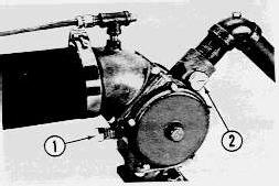
CARBURETOR ADJUSTMENTS
1. Idle Adjustment Screw 2. Power Misture Screw
1. Set the power mixture screw (2) midway between "L" and "R".
2. Turn the idle adjustment screw (1) clockwise all the way in, then out four turns.
3. Set low idle speed on a cold engine. With the engine running, turn the low idle screw (1) to obtain recommended low idle speed (see the Engine Information Plate).
Change the gas pressure delivered by the line pressure regulator to compensate for any change in heat content of the fuel. See your Caterpillar dealer for pressure settings.
Linkage Adjustment
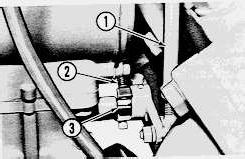
1. Disconnect linkage (1).
2. Turn screw (2) counterclockwise until the throttle plate will close without touching the screw.
3. Turn screw (2) until it touches stop (3) with the throttle plate closed.
LINKAGE ADJUSTMENTS
1. Governor Linkage 2. Throttle Stop Screw 3. Stop
4. With the governor lever in the OFF position and the throttle plate closed, adjust the linkages and reconnect them. (If additional linkage adjustment is necessary, see your Caterpillar dealer.)
5. On Vee engines adjust linkage so that both throttle plates open simultaneously.
Gas Line Pressure
Gas line pressure must be regulated for use in engines. Naturally aspirated engines, using a line pressure regulator, require line pressure of 3 PSI to 20 PSI. A turbocharged engine must have greater working pressure available- 12 PSI to 20 PSI. Twenty PSI is the maximum line pressure which is easily reduced to a working pressure. If gas pressure exceeds 20 PSI, a second regulator will have to be used.
Line Pressure Regulator
The line pressure regulator requires adjustment when the engine is installed, when the regulator is reworked, or when the heat content of the fuel is changed. A water manometer is used to set the regulator output gas pressure.
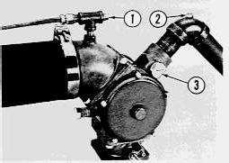
1. Remove plugs (1) and (2) from the carburetor.
CARBURETOR
1. Air Pressure Manometer Plug 2. Gas inlet Plug 3. Power Mixture Screw
2. Connect a water manometer between the two pressure taps.
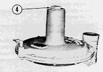
4. Regulator Adjustment Plug
NOTE: A valve is used between the manometer and the carburetor to prevent water from being drawn into the engine during start up. Close the valve during cranking and start up, then open the valve when engine is running.
3. Open the main gas valve.
4. Adjust the gas pressure to support a 51/2 inch (14 cm) column of water, or to correct differential if fuel BTU is known.
5 The regulator adjustment is made by removing plug (4) and turning the slotted cap clockwise to increase output pressure and counterclockwise to decrease pressure.
6. Repeat this procedure for each carburetor.
7. After these initial adjustments the engine can be started.
Adjusting Line Pressure Regualtor With Known BTU Fuel
1. With known BTU fuel, refer to a differential and BTU curve. See Form FE036044, or see your Caterpillar Dealer for pressure setting.
2. Use the curve to find proper differential setting which gives the correct air fuel ration.
3. Follow procedure under line pressure regulator until adjusted gas pressure will support the proper differential with engine at idle condition.
Adjusting Line Pressure Regulator With Unknown BTU Fuels
1. Follow procedure under line pressure regulator for setting which will allow starting of engine.
2. Install accurate tachometer on engine.
3. Remove line regulator plug (4) and install adjusting tool.
NOTE: On turbocharged engines a special tool is necessary to prevent boost pressure from escaping when regulator cap is removed.
4. Start engine and put under constant fixed load. Load should be as near full load as possible with engine running steady.
5. Physically lock carburetor throttle plate in position while engine is operating. (On Vee Engines lock both throttle plates.)
6. Disconnect governor linkage.
7. Adjust regulator slotted cap to get maximum engine RPM. Maximum engine RPM can be found best by starting with a lean mixture and slowly increasing to reach maximum RPM.
8. Reduce the maximum obtainable RPM by 3%. This is done by leaning mixture - turn slotted cap counterclockwise in regulator. This will give proper air fuel ratio.
NOTE: On Vee Engines each side has to be adjusted separately.
9. Reconnect governor linkage and unlock throttle plate.
10. Remove special tool from regulator or install cap.
11. If differential is desired, a manometer may be installed at carburetor point 1 and 2 and read.
Adjusting Power Mixture Screw -
1. Power mixture screw (3) should be adjusted with engine operating at rated load and RPM only.
2. Increase richness until engine reaches its maximum RPM.
3. Turn power mixture screw to lean until engine loses RPM.
4. Turn power mixture screw to rich until engine regains highest RPM.
NOTE: Power mixture screw is only effective at rated load and RPM. With 905 BTU LHV fuel mixture, screw should be set 21/2notches from lean.
Balance Line
Turbocharged engines have a balance line from the carburetor to the line pressure regulator. The balance line transmits manifold air pressure to the upper side of the regulator diaphragm. This force, added to the spring force, ensures that gas pressure to the carburetor will always be greater than inlet air pressure regardless of load conditions. A turbocharged engine will not develop full power without a balance line.
Throttle Synchronization - Vee Engines
Be sure both linkages have been adjusted.
Two turbochargers are used on Vee engines. The air induction system is cross blown, that is, the turbocharger turbine wheel is driven by the exhaust from one bank and the compressor wheel supplies air to the opposite bank. This reduces the amount of unbalanced load possible and keeps one bank from overworking. The maximum amount of unbalance without a loss of power is .3 inches (0,76 cm) of mercury. Unbalance is determined in the following manner.
MANOMETER CONNECTION LOCATION
With the engine stopped:
1. Remove the plug from each manifold and connect the manometer.
2. Close the valve on the manometer and start the engine. Open the valve.
3. Run the engine at 2/3 rated speed and adjust the throttle linkage until the difference in the two columns is within .3 inches (0,76 cm) of mercury. DO NOT change gas pressure to balance the output.
4. Repeat Step 3 with engine at 2/3 load and at rated speed.
Product: GAS ENGINE
Model: G342C GAS ENGINE 71B
Configuration: G342 ENGINE 71B00001-UP
Operation and Maintenance Manual
G342C NATURAL GAS ENGINE Media Number -SEBU5560-01
Periods Of Limited Use
SMCS - 1350; 1352; 1395; 7542-008
Prolonged operation at low idle or reduced load may cause oil consumption and carboning in the combustion chamber and result in poor performance and a loss of power. Every four hours, load the engine to clear carbon from the combustion chamber.
If the engine is to be stored or left standing for a long period of time, the lubricating oil may drain away from the cylinder walls and piston rings. This lack of lubricant permits rings to rust, and causes unnecessary wear by metal-to-metal contact between the pistons and rings when the engine is started. The lack of lubricant may not cause any noticeable change in engine operation after it has been started, but it does contribute to shorter engine life.
If an engine is not going to be used for several weeks, renew the oil film by running the engine once a week until it is thoroughly warm. This will circulate the oil and will prevent rust from forming. Lubricate all points mentioned in the lubrication chart.
If an engine is going to be put in winter storage, see your Caterpillar dealer for storage instructions.
Copyright 1993 - 2024 Caterpillar Inc.
All Rights Reserved.
Private Network For SIS Licensees.
Wed Dec 4 02:29:12 UTC+0530 2024
Product: GAS ENGINE
Model: G342C GAS ENGINE 71B
Configuration: G342 ENGINE 71B00001-UP
Operation
and Maintenance Manual
G342C NATURAL GAS ENGINE
Safety Precautions
SMCS - 1350; 1352; 1395; 7542-008
Safety is basically common sense. There are standard safety rules but each situation has its own peculiarities which cannot always be covered by rules. Therefore, your experience and common sense will be your best guides to safety. Lack of attention to safety can result in: accidents, personal injury, reduction in efficiency and worst of all- loss of life. Watch for safety hazards. Correct deficiencies promptly.
Use the following safety precautions as a general guide to safe operation.
1. Never adjust or repair a machine while in operation.
2. Remove all loose tools and electrical cords from the engine before starting.
3. Keep the engine room and floor area clean.
4. Store oily rags in containers.
5. Never store flammable liquids near the engine.
6. Do not smoke around batteries. Hydrogen gas generated by a charging battery is explosive. Keep batteries in a well ventilated area.
7. Observe NO SMOKING signs.
8. Do not wear loose clothing around machinery.
9. Be sure the engine room is properly ventilated.
10. Always disconnect and tape the ground battery lead before working on the electrical system.
11. All electrical equipment must be grounded according to local building codes.
12. Be sure an automatic start-stop system is inoperative when the engine is being worked on. Disconnect the starter from the start switch.
13. Use the emergency stop button for emergency only. (This procedure shorts out the magneto, thus leaving unburned gas in the manifold.)
14. An overly rich fuel mixture can cause combustion in the exhaust system.
15. All gas lines and valves must meet local codes.
16. Check piping periodically for gas leaks. Remember, safety is everyone's business.
INSTALL GUARDS ON ALL EXPOSED ROTATING COMPONENTS
Product: GAS ENGINE
Model: G342C GAS ENGINE 71B
Configuration: G342 ENGINE 71B00001-UP
Operation and Maintenance Manual
G342C NATURAL GAS ENGINE
Starting
SMCS - 1350; 1352; 1395; 7542-008
Perform required periodic maintenance before starting the engine. Make a "walk-around" check of the installation. It only takes a few minutes to correct minor discrepancies. This can prevent major repairs at a later date.
Pre-Start Checks
1. Check the air cleaner service indicator. If the red piston is locked in the raised position, service the air cleaner.
2. Correct any leaks, loose bolts or covers. The fan and radiator must be clear of restrictions.
3. Check the coolant level. The radiator must be full to the bottom of the filler neck.
DIPSTICK
4. The crankcase oil level must be above the ADD mark.
5. Disconnect any battery chargers that are not protected against the starter current drain.
6. All guards must be in place. If guards are inadequate or in need of repair, notify your supervisor.
Starting Procedure
Electric Start
1. Open the raw water valve-if so equipped.
2. Open the gas valve.
3. Disengage the clutch or open the circuit breaker. Do not start an engine under load.
4. Move the controls to half engine speed position.
5. Reset any safety devices.
Safety Gauges-Push reset button on the magnetic switch and hold the oil pressure reset button in.
Electrical-turn oil pressure switch OFF.
RESET OIL PRESSURE SWITCH
PUSH TO SET OIL PRESSURE SWITCH TO OFF POSITION
6. Start the engine.
7. If the engine fails to start after 30 seconds of cranking, stop. Allow the starter to cool for two minutes. Turn the gas valve OFF and crank the engine for 10 to 15 seconds to purge unburned gas from the exhaust system.
8. Turn the gas valve ON and repeat cranking procedure.
NOTICE
Do not engage the starter when the flywheel is moving.
Clearances and tolerances are designed for operating conditions-including operating temperature. When the engine is started it takes several minutes to establish the lubricating oil film and allow the moving parts to heat up and expand. Loading a cold engine will cause shortened service life, i.e., broken rings, seized pistons, etc. This warm up period allows time for another "walk-around" check for leaks, etc.
If oil pressure fails to register, stop the engine and determine the cause. On the units with an oil pressure switch, the reset knob will move from ON to RUN automatically when oil pressure builds up. If the knob fails to move, stop the engine and determine the cause.
Air Start
Perform all electric starting preliminary checks.
Check the air supply. The air starter must have 100 PSI air pressure available. The standard receiver stores 10.5 cubic ft. (,3 cubic m) of air at 250 PSI. Pressure is reduced at the air starter motor.
Open bleed valve (on the bottom of the receiver) weekly, to drain any condensation and oil carryover.
The lubricator must be filled with oil. See the Lubrication and Maintenance Procedures.
Hydraulic Start
Perform all electric starting preliminary checks.
Check the hydraulic accumulator pressure-it must be 3000 PSI. Copyright 1993 - 2024 Caterpillar Inc.
Product: GAS ENGINE
Model: G342C GAS ENGINE 71B
Configuration: G342 ENGINE 71B00001-UP
Operation and Maintenance Manual
G342C NATURAL GAS ENGINE Media Number -SEBU5560-01
Stopping
SMCS - 1350; 1352; 1395; 7542-008
1. Remove the load from the engine.
2. Allow the engine to run at about half speed for five minutes. This reduces internal temperatures and prevents the loss of coolant by "afterboil".
3. Reduce speed to low idle for about 30 seconds.
4. DO NOT race the engine before shut off. This causes the turbocharger to "coast" without lubrication.
5. Turn gas valve off to stop the engine. Do not use emergency stop button except in emergencies.
Copyright 1993 - 2024 Caterpillar Inc. All Rights Reserved. Private Network For SIS Licensees.
Wed Dec 4 02:30:19 UTC+0530 2024
This is the sample of the sample click on the download link for complete manual