DOWNLOAD LINK
For some reason if link does not work download this pdf and then click
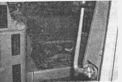
14. OPERATOR'S COMPARTMENT Inspect for cleanliness.
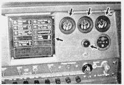
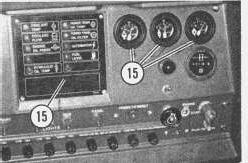
15. INSTRUMENT PANEL Inspect for broken gauges and indicator lights.
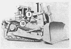
D9L Pre-Start Checks
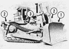
1. Maintain the engine oil to the FULL mark on the dipstick.
2. Maintain the power train system oil to the FULL mark on the dipstick.
3. Maintain the hydraulic implement oil to the FULL mark on the sight gauge.
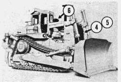
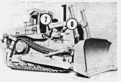
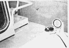
4. Maintain the engine coolant to within 13 mm (1/2 inch) from the bottom of the fill tube.
5. Maintain the fuel to the FULL mark on the dipstick.
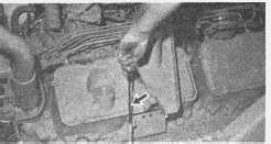
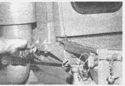
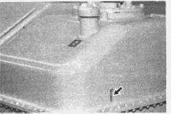
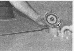
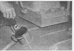
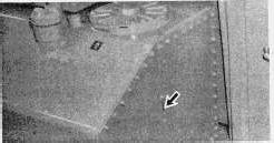
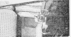
6. Drain the moisture and sediment from the fuel tank.
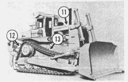
D10 Pre-Start Checks
Maintain the engine oil to the FULL mark on the dipstick.
2. Maintain the power train system oil to the FULL mark on the sight gauge.
3. Maintain the hydraulic implement oil to the FULL mark on the sight gauge.
4. Maintain the engine coolant to the FULL area on the gauge.
1.
5. Maintain the fuel to the FULL mark on the dipstick.
6. Drain the moisture and sediment from the fuel tank.
Copyright 1993 - 2024 Caterpillar Inc. All Rights Reserved. Private Network For SIS Licensees.
Sun Nov 17 22:20:48 UTC+0530 2024
Product: TRACK-TYPE TRACTOR
Model: D9L TRACK-TYPE TRACTOR 14Y
Configuration: D9L TRACTOR 14Y00001-UP (MACHINE) POWERED BY 3412 ENGINE
Operation and Maintenance Manual
D9L and D10 Track Type Tractor - Operation Manual
Media Number -SEBU5811-04
Controls
SMCS - 7310
Brake Pedal
Publication Date -01/10/1986
Date Updated -11/10/2001
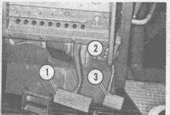
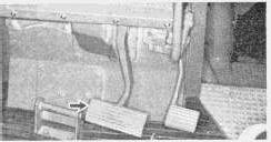
1. Push the brake pedal DOWN to apply the brakes and slow or stop the machine. Use the brakes on a downgrade to keep the engine from overspeeding.
1. RELEASE the brakes to allow the machine to move, or increase ground speed.
Governor Control
2. Pull the lever BACK toward the operator for higher engine RPM. Push the lever FORWARD to slow the engine. Push the lever FORWARD to the detent position for low idle. Push the lever all the way forward to shut off the engine.
Decelerator
Decelerator Pedal (3.) - Push DOWN on the pedal to override the governor control and reduce the engine speed. Use the pedal for directional shifts or for quick engine RPM reduction.
Steering Clutch/Brake Control
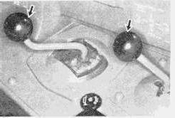
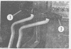
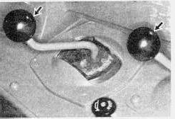
There are two steering clutch/brake control levers. The lever on the operator's left, controls the left steering clutch and brake. The lever on the right controls the right steering clutch and brake.
Left Steering Clutch/Brake Lever (1.) - Pull the left lever (1) back to steer the machine to the left. The rate of steering is controlled by how far the lever is pulled back. When a slight lever pressure is felt while pulling it back, the lever will be entering the braking position. Pull the lever all the way back to brake the left track, for a pivot turn. Pulling only the left lever all the way back will NOT STOP the machine.
Right Steering Clutch/Brake Lever (2.) - Pull lever (2) to steer the machine to the right. Lever (2) controls the right track the same as lever (1) controls the left track.
Transmission/Parking Brake Lever
This lever engages the parking brake and locks the transmission in neutral. The machine should not move when engaged.
Transmission/Parking Brake Unlocked (1.) - Pull the lever up to release the parking brake.
Locked (2.) - Push the lever down to engage the parking brake. This will also lock the transmission in NEUTRAL.
1. The lever controls neutral, forward, reverse and three speeds forward or reverse. Move the lever to the desired direction and speed.
Bulldozer Blade
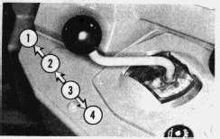
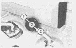
Float (1.) - Push the lever all the way forward into detent for blade FLOAT. In this position, the blade will move up and down following the ground contour.
The lever will remain in the float position (detent) until manually pulled out of detent position. The lever will then return to the HOLD position.
Lower (2.) - Push the lever forward from HOLD to lower the blade. Release the lever and it will return to HOLD.
Hold (3.) - Release the lever from raise or lower, and the lever will return to HOLD. The blade movement will stop.
Raise (4.) - Pull the lever back to raise the blade. Release the lever and it will return to HOLD.
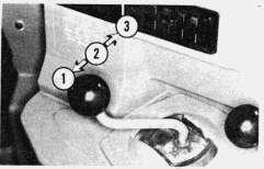
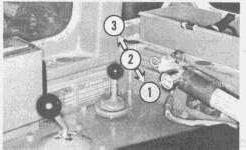
Tilt Left (1.) - Pull the lever to the left to lower the blade to the left. Release the lever and the lever will return to HOLD.
Tilt Hold (2.) - Release the lever and the lever will return to HOLD. The blade movement will stop.
Tilt Right (3.) - Push the lever to the right to lower the blade to the right. Release the lever and the lever will return to HOLD.
Ripper
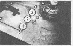
Raise (1.) - Pull the lever to the left to raise the ripper. Release the lever and the lever will return to HOLD.
Hold (2.) - Release the lever and the lever will return to HOLD. The ripper movement will stop.
Lower (3.) - Push the lever to the right to lower the ripper. Release the lever and the lever will return to HOLD.
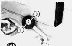
Shank In (1.) - Push the lever forward to move the shank in toward the machine. Release the lever and the lever will return to HOLD.
Shank Hold (2.) - Release the lever and the lever will return to HOLD. The ripper movement will stop.
Shank Out (3.) - Pull the lever back, to move the shank out away from the machine. Release the lever and the lever will return to HOLD.
D9L (Earlier Models) and D10
1. Shank Pin In - Pull the lever toward you to engage the ripper shank pin (detent). Move the lever manually to HOLD, to stop the ripper shank pin movement.
2. Shank Pin Hold - Move the lever to the center, and ripper shank pin movement will stop.
3. Shank Pin Out - Push the lever away from you to disengage the ripper shank pin (detent). Move the lever manually to HOLD, to stop the ripper shank pin movement.
D9L (Later Models)
NOTE: The toggle switch must be pulled up before moving it to operate the ripper shank pin. This will prevent it from being bumped accidentally and operating the ripper shank pin.
1. Shank Pin In - To engage the ripper shank pin (detent), pull up on the toggle switch and move it toward the operator.
Pull the toggle switch up and move it to the center (HOLD) position to stop the ripper shank pin movement.
2. Shank Pin Hold - Pull up on the toggle switch and move it to the center (HOLD) position, and the ripper shank pin movement will stop.
3. Shank Pin Out - To disengage the ripper shank pin (detent), pull up on the toggle switch and move it away from the operator.
Pull the toggle switch up and move it to the center (HOLD) position to stop the ripper's shank pin movement.
Winch
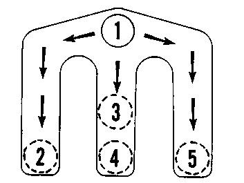
Brake On-Hold (1.) - The cable should not move. Use this position when towing, holding load or when winch is not in use.
Brake Off-Reel In (2.) - To reel in the cable, pull the lever to this position. Release the lever and it will return to HOLD. The cable will move toward the winch under power.
Brake Off-Release (3.) - To RELEASE, pull the lever to this position. Release the lever and it will return to HOLD. The winch brake is released. The cable will unreel by the weight of the load, or when the machine moves away from load, if it is heavy enough.
Brake Off-Release Detent (4.) - The lever will remain in this position until moved manually. The resistance of the winch mechanism makes it impossible to unreel the cable by hand.
Brake Off-Reel Out (5.) - To reel OUT the cable, pull the lever to this position. The cable will reel out under power. Release the lever and it will return to HOLD.
Inching (Fine Control Operation)
For more precise winch operation control, an adjustable sequence valve is located inside the winch. It has either "inching" or "no inch" characteristics during reel in and reel out operations. For adjusting, see "Winching" in the "Operating Adjustments" section of this guide.
1. Inching Out - Pull the lever slowly toward (5) position, until the cable or load starts to move. The farther the lever is pulled back, the faster the cable will move out.
2. Inching In - Pull the lever slowly towards (2) position, until the cable or load starts to move. The farther the lever is pulled back, the faster the cable will move in.
Copyright 1993 - 2024 Caterpillar Inc.
Rights Reserved.
Network For SIS Licensees. Sun Nov 17 22:20:29 UTC+0530 2024
Product: TRACK-TYPE TRACTOR
Model: D9L TRACK-TYPE TRACTOR 14Y
Configuration: D9L TRACTOR 14Y00001-UP (MACHINE) POWERED BY 3412 ENGINE
Operation and Maintenance Manual
D9L and D10 Track Type Tractor - Operation Manual
Media Number -SEBU5811-04
Publication Date -01/10/1986
Fire Suppression System
SMCS - 7310
Date Updated -11/10/2001
The Fire Suppression System will not be able to suppress a fire and protect the operator unless the nitrogen and agent cylinders are fully charged.
The nitrogen and agent cylinders must be recharged if the system has been activated. Consult your Caterpillar dealer for recharging information.
Fire suppression agents, either Halon or dry chemical type, may create hazards to people if discharged on them.
Fire suppression agent can cause breathing difficulties and/or skin irritation. To prevent accidental discharge during maintenance or repair work, put the disconnect switch in the OFF position.
Fire suppression agents can irritate eyes, skin and nasal passages. If the agent gets into eyes, flush thoroughly with water, then consult a physician. In case of skin contact, wash all exposed areas with soap and water. If irritation persists, after inhalation or skin contact, consult a physician.
The purpose of the fire suppression system is to suppress an oil, fuel or debris fire, long enough to allow the operator to safety leave the tractor.
The fire suppression system will not suppress fires outside the tractor. It will not suppress fires in the operator's compartment.
There are agent dispersion nozzles strategically located in the power train compartments and the engine compartment.
NOTE: A fire suppression system is not meant to be a substitute for a hand-held fire extinguisher. Fire extinguishers are still recommended, and are useful if re-ignition occurs or when fires originate independently of a machine or outside a protected area.
To Activate Fire Suppression System (D9L Earlier Models and D10)
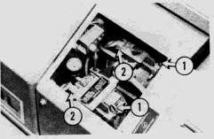
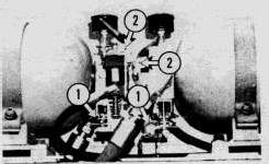
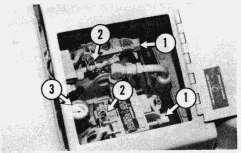
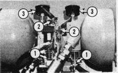
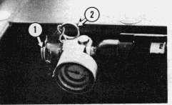
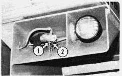
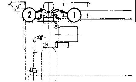
The system will not discharge the agent with the lock pins in the valve trip lever (1).
To prevent accident agent discharge when shipping or servicing the machine, each lock pin must be removed from the manual release handle (2) and installed in the agent cylinder valve trip lever (1).
D9L
D10
D9L
Before operating machine, each pin must be pulled from the valve trip lever (1) and installed in the manual release handle (2). Check daily before operating machine, to make sure the pins are in this position.
The agent cylinders temperature gauges (3), should be at or above the outside temperature.
When the Suppression Agent is a dry chemical, the cylinder pressure gauges should be in the green range. If not, have them charged before starting the engine.
Discharge of the Fire Suppression System
The system is designed to be activated from any of three areas.
Actuation from Operator's Compartment
The nitrogen actuator lever has a lock pin that keeps the actuator lever from accidentally being pulled up and discharged.
To discharge the agent cylinders, proceed with the following steps.
1. Stop the machine.
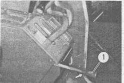
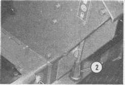
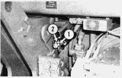
2. Pull the lock pin (1) out of the nitrogen actuator lever.
3. Lift the nitrogen actuator lever (2) to discharge the agent cylinders.
4. Get off machine, using steps and grab irons. However, if time permits, complete the following steps:
A. Lower all raised equipment.
B. Shift the transmission to neutral.
C. Engage the transmission parking brake lock lever.
D. Shut off the engine if the automatic shut down system did not shut it off.
Actuation from Rear of Tractor:
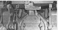
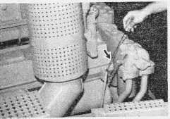
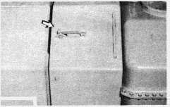
1. Pull the lock pin (1) from the nitrogen actuator lever (2), located under the fuel tank.
2. Lift the lever (2), to discharge the nitrogen actuator.
3. The engine should shut off.
Alternative Manual Actuation of the System:
When the nitrogen actuators do not activate the fire suppression system, from the operator's compartment or from the rear of the machine, an alternative actuation method is provided.
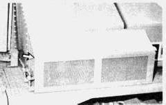
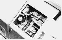
1. Lift the agent cylinder's cover, located on the right side of the machine.
D9L
D10
D9L
1. Lift the agent cylinder's cover, located on the left side of the machine.
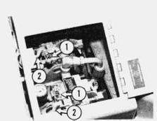
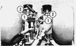
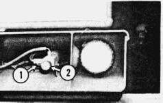
2. Pull out the lock pin (1) in each manual actuator lever (2).
3. Pull up on each manual actuator lever (2).
4. Get off the machine.
If the machine must be moved, the engine can be restarted approximately 10 seconds after the discharge of agent cylinders.
Engine Shut Down System
The engine should shut off automatically when the agent system discharges.
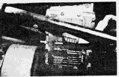
To make certain the automatic engine shut down system is operable, a test switch is provided on the D9L. The D10 does not have a test switch.
D10
D9L
D10
With the engine operating, push the test switch. The engine should stop.
If the engine does not stop, have the system repaired before operating.
Automatic Actuation (D9L Later Models)
The fire suppression system is electrically (automatic mode) or manually actuated. It works even if the machine is unattended or not in operation. Should a fire occur while the engine is running and the parking brake is engaged, the system automatically actuates while simultaneously shutting down the engine by an electrinically controlled fuel shutoff. Even with the key off and the machine parked, the system will continue to monitor heat and activate if a fire is detected.
Should a fire occur while the machine is in operation (parking brake not engaged), the system will actuate but will not shut down the engine. This allows the operator to move the machine to a safe shutdown area.
Once a sensor has detected a fire, an electrical signal warns the operator and actuates the system. A solenoid in the operator's compartment triggers a pin in the actuation cylinder that ruptures a burst disc, releasing nitrogen gas into the line between the actuation cylinder and the agent cylinder. This "stored" energy depresses a piston in the agent cylinder rupturing another burst disc which releases pressurized liquid Halon 2402 or dry chemical into the lines and out of the nozzles. Either dry chemical or Halon 2402 are effective suppressants. Dry chemical, however, requires cleanup of residue to prevent corrosion.
Manual Actuation (D9L Later Models)
If necessary, the system can be manually actuated either from the cab or rear of machine. The operator removes a safety pin from the actuation cylinder and depresses a plunger puncturing the burst disc. The system then proceeds as with the automatic sequence.
Actuation from Operator's Compartment
The nitrogen cylinder has an actuator lock pin that keeps the cylinder from being accidentally discharged. To activate the fire suppression system, remove the lock pin and depress the plunger.
1. Stop the machine.
2. Pull the lock pin (1) out of the nitrogen cylinder actuator.
3. Depress the nitrogen cylinder actuator plunger (2) to discharge the agent cylinder.
4. Get off machine, using the steps and handholds. However, if time permits, complete the following steps:
A. Lower all raised equipment.
B. Shift the transmission to neutral.
C. Engage the transmission parking brake lock lever.
D. Shut off the engine if the automatic shutdown system did not shut it off.
Actuation from Rear of Machine
1. Pull the lock pin (1) out from the nitrogen cylinder actuator, located under the fuel tank on rear end of the machine.
2. Depress the nitrogen cylinder actuator plunger (2) to discharge the agent cylinder.
3. The engine should shut off.
Electronic Fire Monitor Control Panel (D9L Later Models)
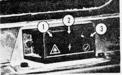
All new machines have an electronic fire monitor control panel located on the dash to alert the operator of a fire on the machine or a problem in the fire suppression system.
1. Fire Indicator - This red indicator will flash and a horn will "BEEP" to indicate that there is a fire on the machine and that the fire suppression system has been activated.
NOTE: It is important to note that the electronic fire monitor control panel is wired to the same fuse as that of the operator monitor (EMS), thus being controlled by the key switch, whereas, the automatic fire suppression control panel can only be electrically disconnected by turning off the machine disconnect switch. Also, when the fire warning horn is "BEEPING," it does so at a rate greater than that of the machine EMS system warning horn.
2. System Fault Indicator - This light indicates that the actuation or agent cylinder pressure has dropped below an acceptable level. It will also indicate a problem in the wiring circuit, such as, faulty sensor circuits, an engine shutdown solenoid or a discharge actuator solenoid. When this light comes on, find the problem and have the problem repaired before operating.
3. Engine Shutdown Test Push-Button - The engine should shut off automatically when the agent system discharges. To make certain the automatic engine shutdown system is operable, a test push-button is provided. With the key switch in the "RUN" position and the parking brakes applied, push the test push-button.
The fire suppression monitor "Fire" indicator should flash, the horn should "BEEP" and the engine shutdown solenoid should energize and shut down the engine. Activation of the test push-button will not result in a system discharge.
If the engine does not stop, have the system repaired before operating.
Automatic Fire Suppression Control Panel (D9L Later Models)
There are eight lights located on the automatic fire suppression control panel that function as service lights for troubleshooting the electrical system. It is located beneath the floor plate of the cab.
Refer to the Service Manual for complete troubleshooting procedures of the fire suppression system.
Copyright 1993 - 2024 Caterpillar Inc. All Rights Reserved. Private Network For SIS Licensees.
Sun Nov 17 22:20:38 UTC+0530 2024
Product: TRACK-TYPE TRACTOR
Model: D9L TRACK-TYPE TRACTOR 14Y
Configuration: D9L TRACTOR 14Y00001-UP (MACHINE) POWERED BY 3412 ENGINE
Operation and Maintenance Manual
D9L and D10 Track Type Tractor - Operation Manual
Media Number -SEBU5811-04
Foreword
SMCS - 7310
Publication Date -01/10/1986
Date Updated -11/10/2001
This Guide is a reference for the new operator and a refresher for the experienced one. Readstudy - and keep it handy.
Illustrations help guide the operator through the correct procedures of checking, starting, operating and stopping the vehicle and attachments.
Operating techniques outlined in the guide are basic. Skill and techniques develop as the operator gains knowledge of the vehicle and its capabilities.
Your safety and the safety of others depends upon care and judgment in the operation of this vehicle. A careful operator is good insurance against an accident.
Some photographs in this publication may show details or attachments that may be different from your unit. Also, the Rollover Protective Structure (ROPS), or guards, for some photographs, may have been removed for illustrative purposes.
Continuing improvement and advancement of product design may cause changes to your machine which may not be included in this publication. Each publication is reviewed and revised, as required, to update and include these changes in later editions.
When a question arises regarding your Caterpillar product, or this publication, please consult your Caterpillar dealer for the latest available information.
Copyright 1993 - 2024 Caterpillar Inc.
All Rights Reserved.
Private Network For SIS Licensees.
Sun Nov 17 22:18:34 UTC+0530 2024
Product: TRACK-TYPE TRACTOR
Model: D9L TRACK-TYPE TRACTOR 14Y
Configuration: D9L TRACTOR 14Y00001-UP (MACHINE) POWERED BY 3412 ENGINE
Operation and Maintenance Manual
D9L and D10 Track Type Tractor - Operation Manual
Media Number -SEBU5811-04
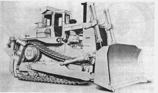
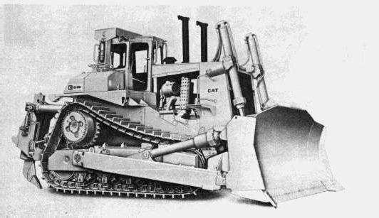
Model Views
SMCS - 7310
Publication Date -01/10/1986
Date Updated -11/10/2001
Copyright 1993 - 2024 Caterpillar Inc.
Rights Reserved.
Network For SIS Licensees.
Product: TRACK-TYPE TRACTOR
Model: D9L TRACK-TYPE TRACTOR 14Y
Configuration: D9L TRACTOR 14Y00001-UP (MACHINE) POWERED BY 3412 ENGINE
Operation and Maintenance Manual
D9L and D10 Track Type Tractor - Operation Manual
Media Number -SEBU5811-04
Moving the Machine
SMCS - 7310
Publication Date -01/10/1986
Date Updated -11/10/2001
1. RAISE all lowered implements, enough to clear any obstructions.
2. Push DOWN on the brake pedal, to keep the machine from moving.
3. Pull UP to disengage the transmission/parking brake lock lever.
This is the sample of the manual click on the download link for complete manual