DOWNLOAD LINK
For some reason if link does not work download this pdf and then click
Product: TRACK-TYPE TRACTOR
Model: D9H TRACK-TYPE TRACTOR 90V
Configuration: D9H TRACTOR 90V00001-UP (MACHINE) POWERED BY D353 ENGINE
Operation and Maintenance Manual
D9H TRACTOR
Media Number -SEBU5229-02
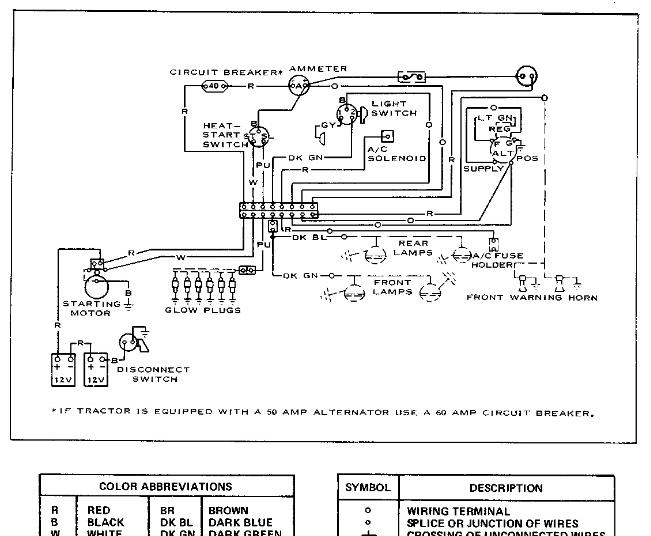
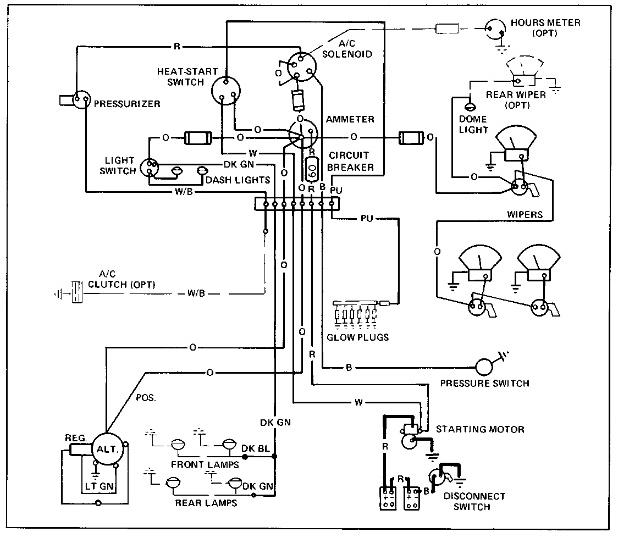
Wiring Diagram
SMCS - 7320-017
Publication Date -01/02/1978
Date Updated -11/10/2001
Copyright 1993 - 2024 Caterpillar Inc.
Rights Reserved.
Tue Oct 22 09:57:04 UTC+0530 2024
Product: TRACK-TYPE TRACTOR
Model: D9H TRACK-TYPE TRACTOR 90V
Configuration: D9H TRACTOR 90V00001-UP (MACHINE) POWERED BY D353 ENGINE
Operation and Maintenance Manual
D9H TRACTOR
Media Number -SEBU5229-02
Publication Date -01/02/1978
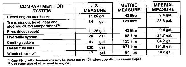
Refill Capacities (Approximate)
SMCS - 7320-017
Date Updated -11/10/2001
Tue Oct 22 09:56:45 UTC+0530 2024
Product: TRACK-TYPE TRACTOR
Model: D9H TRACK-TYPE TRACTOR 90V
Configuration: D9H TRACTOR 90V00001-UP (MACHINE) POWERED BY D353 ENGINE
Operation and Maintenance Manual
D9H TRACTOR
Media Number -SEBU5229-02
When Required
SMCS - 7320-017
Publication Date -01/02/1978
Date Updated -11/10/2001
(29)Transmission, Bevel Gear And Steering Clutch Compartment
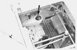
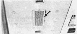
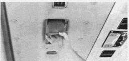
Check oil level with engine at low idle and transmission in NEUTRAL. Maintain oil level between ADD and FULL marks on dipstick.
Add oil if required.
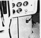
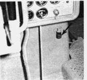
NOTE: If tractor is equipped with a modular cab, the transmission level dipstick and filler tube are located above batteries on outside of cab (see page 13).
(30)Torque Divider Suction Screen
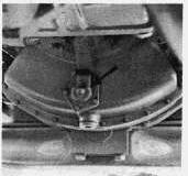
1. Wash suction screen whenever common oil compartment is drained for repairs on brakes, transmission or torque divider.
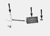
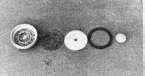
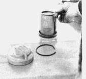
2. Remove cover, housing, spring and screen.
3. Separate cover, housing spring and screen. Wash screen in clean solvent.
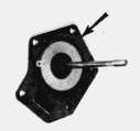
4. Inspect cover gasket. Install new cover gasket if necessary.
5. Install screen, spring and housing to cover. Be sure pin in housing is aligned with hole in cover.
6. Install suction screen assembly. (31)Winch
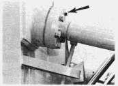
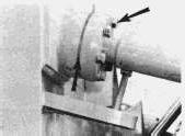
1. Check oil level with engine running at low idle. Oil must be visible in sight gauge. Add oil if necessary.
Check cable. If cable is worn or frayed install a new cable.
Installing Cable
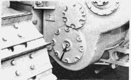
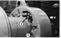
Cable is attached to the drum on the winch with a standard cable ferrule. The ferrule is fitted into a socket on the drum and secured with a bolt-down clamp.
Ferrules are made in various diameters and lengths. When ordering cable from your local supplier, use the following guide to specify the correct ferrule.
NOTICE
1 1/4 in. (32 mm) diameter cable is to be used for extended cable life only. It is not to be used for increasing winch capacity.
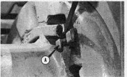
Put the cable in a straight line behind the tractor. Install clamp (A).
Remove clamp (A). Install cable end into groove (B).
(32)Final Drives
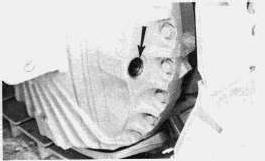
1. Remove fill plug.
2. Check oil level. Oil should be up to the filler plug opening. Add oil as required.
(33)Track-Adjustment
NOTE: Tracks should be adjusted under the same conditions in which the machine will be used. If packing conditions prevail on the job, the tracks should be adjusted with packing present.
Run the tractor in the forward direction at least twice the length of the tractor, then allow tractor to coast to a stop. Do not brake tractor to stop it.
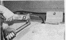
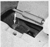
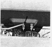
1. Raise inspection plate and add MPG through fill valve until idler moves forward and track is tight.
NOTICE
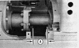
Do not attempt to tighten track when stop on adjusting rod is within 0.25 inch (6 mm) diamension "A" of stop on roller frame. Contact your Caterpillar dealer for track service.
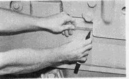
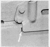
2. Make a mark on the roller frame 1/2 inch (1 cm) behind the idler bearing support.
3. Make sure there is space for the front idler to retract.
Raise inspection plate.
Never visually inspect relief valve to see if grease is escaping. Always observe the track to see if it has loosened.
Open relief valve 1 turn only.
4. Open relief valve and allow the idler to move back. Moving the machine back and forth, will help move the idler back.
5. Close relief valve.
6. Add MPG through the fill valve until mark on roller frame is aligned with the rear edge of idler bearing support.
NOTE: If correct adjustment cannot be obtained, see your Caterpillar dealer for track service.
(34)Prescreen
1. Check prescreen for damage and replace if necessary.
2. Wash prescreen in clean solvent, if required, to remove dust and debris on screen.
(35)Engine Air Intake System
Never service air cleaners with engine running.
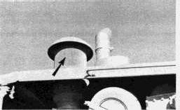
Service filter elements when RED indicator locks in the visible position.
Primary Element
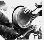
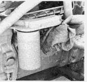
1. Remove cover and primary element.
2. Clean inside of body and cover.
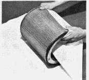
3. Clean and inspect element. (See Page 30).
NOTICE
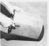
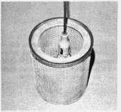
Always inspect primary element before and after cleaning with a light bulb inside element. Discard if any tears, rips or damage is evident.
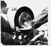
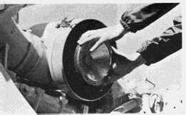
4. Install clean element and cover.
5. Reset indicator.
If indicator shows RED shortly after installation of a primary element which has been cleaned approximately 6 times, change to another clean element.
NOTE: The primary element should be replaced after being cleaned a maximum of 6 times. Replace the element once a year even though it has not been cleaned 6 times.
If indicator still shows RED shortly after the installation of the clean primary element, change the secondary element.
Replace the secondary element at the time the primary element is cleaned for the fourth time.
NOTICE
Always replace the secondary element. Do not attempt to reuse by cleaning.
Secondary Element
1. Remove cover and primary element.
2. Remove secondary element.
3. Cover air inlet opening. Clean inside of air cleaner body.
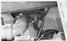
4. Inspect precleaner, dust ejector and exhaust venturi. Clean all parts when necessary.
5. Clean parts with compressed air, a stiff fiber brush or wash in water and non-sudsing detergent. Dry all parts before installation. *
6. Uncover air inlet opening.
7. Install new secondary element and retainer. Tighten nuts to 20 ± 5 lb. ft. (2.8 ± 0.7 mkg).
8. Install primary element and cover.
9. Reset filter indicator.
When using pressure air, wear safety face shield and protective clothing. Use 30 PSI (2 kg/cm2) maximum pressure air for cleaning pressure.
Cleaning Air Cleaner Elements
Pressure Air - 30 PSI (2 kg/cm2) Maximum
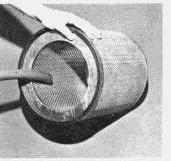
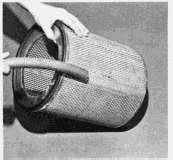
2. Direct air outside along length of pleats. Direct air inside along length of pleats. Check element.
Water - 40 PSI (3 kg/cm2) Maximum
1. Direct air inside element along length of pleats.
1. Direct water inside element along length of pleats.
2. Direct water outside along length of pleats. Rinse, air dry thoroughly and check.
Detergent
1. Wash in warm water and non-sudsing household detergent.
2. Rinse with clean water, 40 PSI maximum (3 kg/cm2), see above.
3. Air dry thoroughly and check.
Checking Element
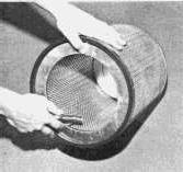
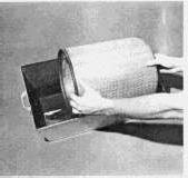
1. Insert light inside clean and dry element and check. Discard element if tears or rips are found.
2. Wrap and store good elements in a clean dry place.
When using pressure air, wear safety face shield and protective clothing. Use 30 PSI (2 kg/cm2) maximum pressure air for cleaning pressure.
NOTICE
Do not clean elements by bumping or tapping.
Do not use elements with damaged pleats, gaskets or seals.
NOTE: Have spare elements on hand to use while cleaning used elements.
(36)Fuel System
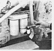
Primary Fuel Filter - Clean Element When Fuel Pressure Gauge Registers OUT With Engine Running.
1. Stop engine and close fuel supply valve.
2. Remove case and element. Wash case and element in clean solvent.
3. Install element and case.
4. Open fuel supply valve.
5. Start engine and check for leaks.
NOTE: Change final fuel filters if fuel pressure gauge still registers OUT with engine running.
Final Fuel Filters
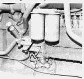
1. Stop engine, close fuel supply valve and remove filters.
2. Clean filter base. Make sure all of old gasket is removed. Coat gasket of new element with clean diesel fuel.
3. Install new filters. Tighten filters until gasket surfaces contact base, then tighten an additional 1/2 to 3/4 turn.
4. Open fuel supply valve and prime fuel system (see below).
5. Start engine and check for leaks.
Priming Fuel System
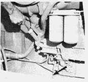
1. Open bleed valve.
2. Unlock priming pump plunger and operate pump until flow of fuel from drain line contains no air bubbles.
3. Close bleed valve.
4. Start engine and check for leaks.
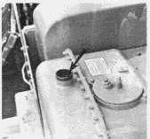
Fuel Tank And Filler Cap
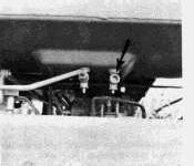
Open drain valve and drain off any sediment or water that have accumulated.
1. Remove cap and filler screen.
2. Disassemble cap and wash cap and screen in clean solvent.
(37)Diesel
3. Oil elements lightly. Assemble cap and install screen and cap.
(38)Cooling System - Cleaning
NOTE: If machine is to be stored or shipped to an area with below freezing temperatures and for information concerning draining and filling the cooling system, refer to Item (27) on Page 20.
1. Drain coolant as outlined in Item (27).
2. Close radiator drain valve and install block drain plug. Fill system with cleaning solution. 1
3. Start engine and run for 1/2 hour. Stop engine and drain cleaning solution (see Item (27)).
4. Flush system with clean water until draining water is clean. Do not run engine while flushing.
5. Close radiator drain valve and install block drain plug. Fill system with neutralizing solution. 2
6. Start and run engine for 10 minutes. Stop engine and drain system (see Item (27)).
7. Flush system with clean water until draining water is clear. Do not run engine while flushing.
8. Close radiator drain valve and install block drain plug. Add coolant slowly, 5 U.S. gallons per minute (19 litres per minute) or less, to proper level.
12 lb. Sodium Bisulphate (NaHSO4) per 10 gallons water (25 grams per litre).
21/2 lb. Sodium Carbonate Crystals Na2CO3, * 10 H2O) per 10 gallons water (6 grams per litre).
NOTE: Most commercial system cleaners may be used.
Use all cleaning solutions with care.
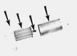
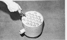
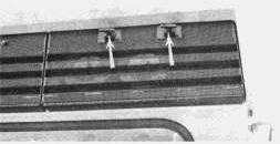
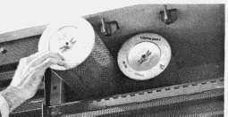
1. Open cover and remove filter elements.
2. Clean elements by using pressure air or by tapping element on a smooth object.
When using pressure air, wear safety face shield and protective clothing. Use 30 PSI (2 kg/cm2) maximum pressure air for cleaning pressure.
Recirculating Filter
1. Remove cover and remove filter element.
2. Clean element with pressure air or wash element in warm water and a non-sudsing household detergent, rinse in clean water and air dry thoroughly.
3. Install element.
3. Install elements.
When using pressure air, wear safety face shield and protective clothing. Use 30 PSI (2 kg/cm2) maximum pressure air for cleaning pressure.
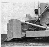
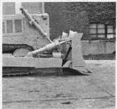
(40)Bulldozer - Diagonal Arm and Tilt Brace Ball and Socket Adjustment
1. Remove cap bolts. Shorten brace and remove shims.
2. Clean ball and socket. Clean shims.
3. Lengthen brace. Install and tighten bolts evenly.
4. Measure clearance between cap and socket with shims.
5. Remove bolts and shorten brace. Install shims equal to measured clearance plus 1 shim.
6. Lengthen brace and install bolts.
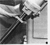
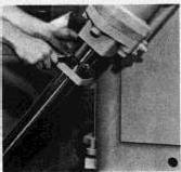
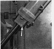
(41)Hydraulic Cylinders - Shim adjusted rod packing
1. Lower blade and stop engine.
2. Move hydraulic controls to relieve pressure.
NOTICE
Use care when removing shims so that cylinder rod is not damaged.
3. Remove bolts and slide flange away from cylinder head.
4. Cut and remove 1 shim.
5. Slide flange back and install bolts. Start engine and check for leaks.
6. If still leaking, remove another shim. Leave at least 2 shims. If packing still leaks, see your Caterpillar dealer.
(42)Ripper
Protector and Tip
(43)Cutting Edge And End Bits
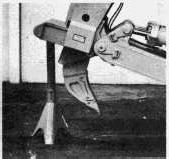
1. Raise and block ripper.
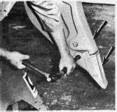
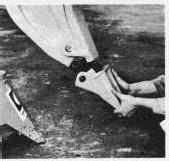
2. Drive pins out, remove protector or tip.
3. Clean pins and shank.
4. Slide new protector or tip on shank and install pins.
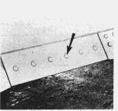
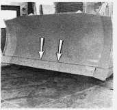
1. Raise and block blade before changing cutting edge or end bits.
3. Remove cutting edge or bit. Clean contact surfaces.
4. Use opposite cutting edge if not worn. Use new section if both edges are worn.
2. Remove bolts.
5. Use new end bits.
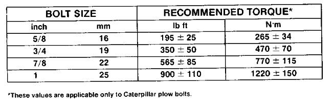
6. Install bolts and tighten to specified torque. (See PLOW BOLT TORQUE CHART).
7. After a few hours of operation retighten bolts to proper torque.
Copyright 1993 - 2024 Caterpillar Inc. All Rights Reserved. Private Network For SIS Licensees.
Tue Oct 22 09:56:21 UTC+0530 2024
Product: TRACK-TYPE TRACTOR
Model: D9H TRACK-TYPE TRACTOR 90V
Configuration: D9H TRACTOR 90V00001-UP (MACHINE) POWERED BY D353 ENGINE
Operation and Maintenance Manual
D9H TRACTOR
Media Number -SEBU5229-02
Publication Date -01/02/1978
Every 2000 Service Hours Or 1 Year
SMCS - 7320-017
(26)Hydraulic Control System
Date Updated -11/10/2001
1. Position tractor on level ground. Lower all equipment. Stop engine and remove filler cap.
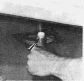
2. Remove plate under fender and remove drain plug. (Insert a 1 inch (25.4 mm) pipe nipple, approximately 6 inches (152 mm) long, into drain to relieve check valve. Allow oil to drain.
This is the sample of the manual click on the download link for complete manual