Product: TRACK-TYPE TRACTOR
Model: D7G TRACK-TYPE TRACTOR 64V
Configuration: D7G TRACK-TYPE TRACTOR / DIRECT DRIVE / 64V00995-UP (MACHINE) POWERED BY 3306 ENGINE
Operation and Maintenance Manual
D7G, D8K & D9H TRACK-TYPE TRACTORS
Media Number -SEBU5473-01
After Starting
Publication Date -01/12/1982
Date Updated -11/10/2001
NOTICE
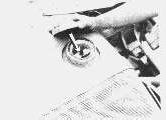
Keep engine speed low until oil pressure registers, if oil pressure does not register within 10 seconds, stop engine and investigate.
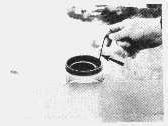
Observe air cleaner service indicator. Push release button. If RED piston remains in, or returns to, the visible position, have air cleaner serviced.
Operate engine under light load for 5 minutes.
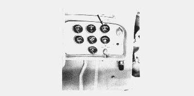
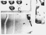
Observe gauges frequently during operation. All gauges must indicate in the NORMAL operating range. The ammeter is normal when the indicator is at or on the + side of zero.
If tractor is equipped with WATER PRESSURE and WATER TEMPERATURE gauges, both gauges should register in the same color ranges. Do not operate when TEMPERATURE gauge indicator is BEYOND color range indicated by PRESSURE gauge. However, the tractor may be operated if PRESSURE gauge indicator is BEYOND color range indicated by TEMPERATURE gauge. Copyright 1993 - 2024 Caterpillar Inc. All Rights Reserved. Private Network For SIS Licensees. Sun Jun 2 22:36:35 UTC+0530 2024
Product: TRACK-TYPE TRACTOR
Model: D7G TRACK-TYPE TRACTOR 64V
Configuration: D7G TRACK-TYPE TRACTOR / DIRECT DRIVE / 64V00995-UP (MACHINE) POWERED BY 3306 ENGINE
Operation and Maintenance Manual
D7G, D8K & D9H TRACK-TYPE TRACTORS
Media Number -SEBU5473-01
Before Starting
Walk-Around Checks
Publication Date -01/12/1982
Date Updated -11/10/2001
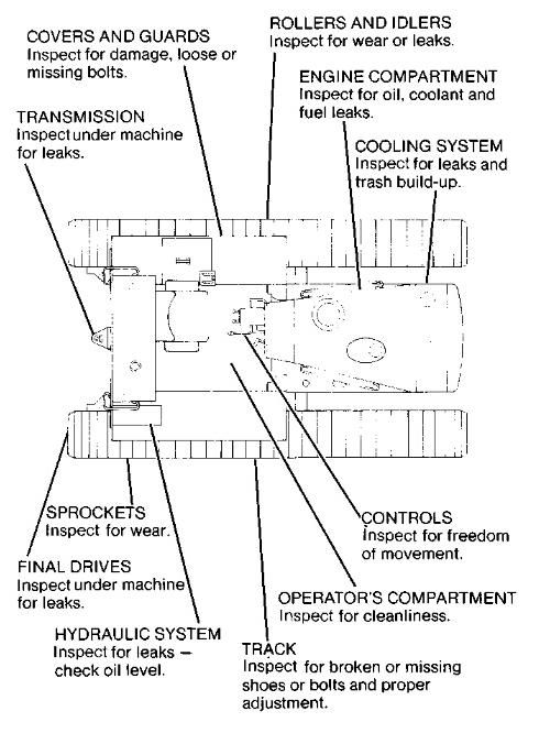
For your own safety, and maximum service life of the tractor, a thorough walk-around inspection should be made before mounting the machine to start the engine. Inspect around and under machine for such items as loose bolts, trash build-up, lubricant, fuel or coolant leaks, and condition of track and implements.
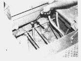
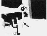
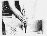
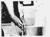
1. Crankcase oil level must be in SAFE STARTING RANGE on ENGINE STOPPED side of dipstick (D9H illustrated).
This is the sample of the manual click on the download link for complete manual
DOWNLOAD LINK
For some reason if link does not work download this pdf and then click
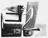
2. Maintain coolant level within 1/2 inch (1 cm) of bottom of fill pipe.
3. Observe diesel fuel level.
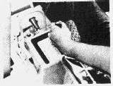
4. Observe air cleaner service indicator. Service filter elements if RED indicator is locked in visible position.
5. Observe hydraulic system oil level.
6. Measure transmission oil level.
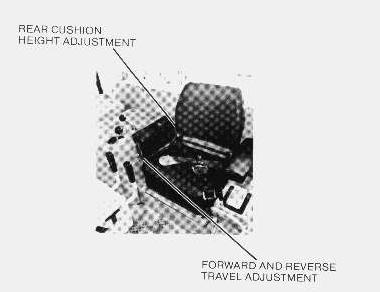
Seat Adjustment - Power Shift and Direct Drive
Seat adjustment should be checked at the beginning of eah shift and when operators change.
Always use seat belt when operating machine.
Always check condition of seat belt and connecting brackets.
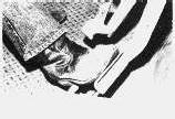
Adjust seat to allow full brake pedal travel with operator's back against seat back. This will permit application of maximum force on brake pedals.
Product: TRACK-TYPE TRACTOR
Model: D7G TRACK-TYPE TRACTOR 64V
Configuration: D7G TRACK-TYPE TRACTOR / DIRECT DRIVE / 64V00995-UP (MACHINE) POWERED BY 3306 ENGINE
Operation and Maintenance Manual
D7G, D8K & D9H TRACK-TYPE TRACTORS
Media Number -SEBU5473-01
Controls
Power Shift (D9H Shown)
Publication Date -01/12/1982
Date Updated -11/10/2001
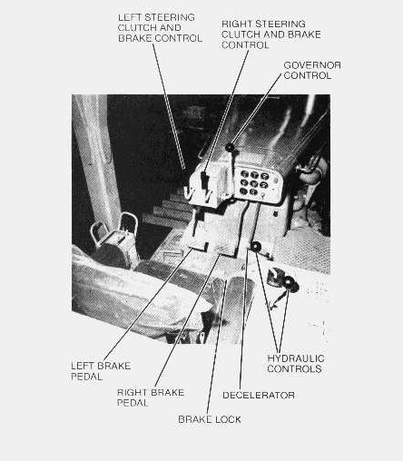
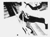
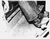
Brake Pedals
Depress brake pedals to stop machine, or to keep engine from overspeeding on down grade.
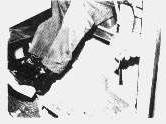
Brake Lock: Earlier Models
1. To ENGAGE brake lock: Depress both brake pedals fully down and push brake lock lever.
2. To DISENGAGE brake lock: Depress both brake pedals fully down and disengage brake lock lever.
Brake Lock: Later Models
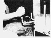
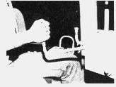
1. To ENGAGE brake lock: Depress left brake pedal firmly. Push the brake lock lever down. Depress right brake pedal firmly.
ONLY THE LEFT PEDAL WILL STAY DOWN.
2. To DISENGAGE brake lock: Depress both brake pedals firmly, then pull the brake lock lever up.
Brake Lock - Modular Cab
To LOCK parking brake: Depress brake pedals first and then ENGAGE transmission control lever safety lock.
To RELEASE parking brake: Depress brake pedals first and then RELEASE transmission control lever safety lock.
Steering Clutches
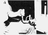
Release right steering clutch by moving lever to detent.
Release right steering clutch and apply right brake by moving lever fully out.
Release left steering clutch by moving lever to detent.
Release left steering clutch and apply left brake by moving lever fully out.
Decelerator
Push decelerator to override governor control and reduce engine speed. Release decelerator to increase engine speed to governor control setting.
Hydraulic
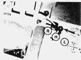
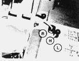
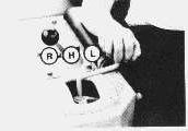
Ripper Height Control
(R) RAISE (H) HOLD (L) LOWER
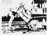
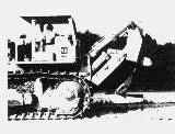
Adjustable Ripper Angle Control - Model D Ripper Only
NOTE: RAISE, HOLD and LOWER positions operate the adjustable ripper in the same manner as the hydraulic non-adjustable ripper control.
Minimum Tooth Angle
Move ANGLE lever FORWARD.
Maximum Tooth Angle
Move ANGLE lever to the REAR.
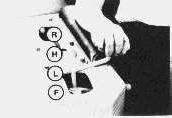
Hydraulic Blade Lift
(R) RAISE (H) HOLD (L) LOWER (F) FLOAT
Hydraulic Blade Tilt
Engine Governor Control
Pull to just past detent to start engine - push fully forward to stop engine.
Pull governor out to obtain desired engine RPM.
(L) LOWER LEFT SIDE (R) LOWER RIGHT SIDE (H) HOLD
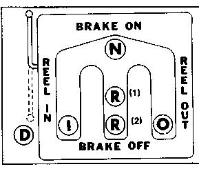
Winch Control
(N) BRAKE ON (NEUTRAL)
(O) REEL OUT
(R) (2)BRAKE OFF DETENT
(I) REEL IN
(R) (1)BRAKE OFF (RELEASE)
(D) DRUM DISCONNECT
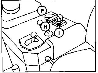
Ripper Hydraulic Pin Puller - D8K, D9G
(P) PULL PIN (H) HOLD (I) INSERT PIN
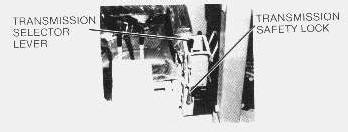
Transmission Controls - Power Shift (D7G, D8K, D9G)
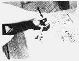
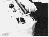
Transmission Safety Lock
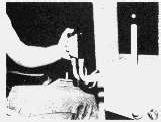
Pull UP on lever to allow shifting of transmission.
Push transmission lever to NEUTRAL and push safety LOCK - DOWN to lock transmission in neutral.
Transmission Selector Lever
Start engine in NEUTRAL with safety lock ENGAGED.
Release safety lock and move selector lever to desired direction and speed.
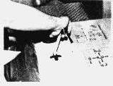
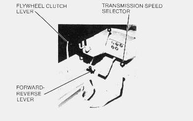
Transmission Controls - Direct Drive (D7G, D8K only)
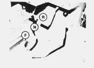
Forward-Reverse Lever
(R) REVERSE DIRECTION
(N) NEUTRAL
(F) FORWARD DIRECTION
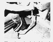
Transmission Speed Lever
NOTICE
Have FORWARD-REVERSE LEVER in NEUTRAL before moving shift lever.
Move lever to desired travel speed.
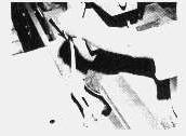
Flywheel Clutch Lever
Pull lever to the REAR to ENGAGE clutch. Push FORWARD to DISENGAGE clutch.
Move lever fully FORWARD to ENGAGE flywheel CLUTCH BRAKE. Copyright 1993 - 2024 Caterpillar Inc. All Rights Reserved. Private Network For SIS Licensees.
Sun Jun 2 22:21:56 UTC+0530 2024
Product: TRACK-TYPE TRACTOR
Model: D7G TRACK-TYPE TRACTOR 64V
Configuration: D7G TRACK-TYPE TRACTOR / DIRECT DRIVE / 64V00995-UP (MACHINE) POWERED BY 3306 ENGINE
Operation and Maintenance Manual
D7G, D8K & D9H TRACK-TYPE TRACTORS
Media Number -SEBU5473-01
Foreword
Publication Date -01/12/1982
Date Updated -11/10/2001
This guide is a reference for the new operator and a refresher for the experienced one. ReadStudy - and keep it handy.
Illustrations help guide the operator through the correct procedures of checking, starting, operating and stopping the vehicle and attachments.
Operating techniques outlined in the guide are basic. Skill and techniques develop as the operator gains knowledge of the vehicle and its capabilities.
Your safety and the safety of others depends upon care and judgment in the operation of this vehicle. A careful operator is good insurance against an accident.
Some photographs in this publication may show details or attachments that may be different from your unit. Also, the Rollover Protective Structure (ROPS), for some photographs may have been removed for illustrative purposes.
Continuing improvement and advancement of product design may cause changes to your machine which may not be included in this publication. Each publication is reviewed and revised, as required, to update and include these changes in later editions.
When a question arises regarding your Caterpillar product, or this publication, please consult your Caterpillar dealer for the latest available information.
Copyright 1993 - 2024 Caterpillar Inc. All Rights Reserved. Private Network For SIS Licensees.
Sun Jun 2 22:20:55 UTC+0530 2024
Product: TRACK-TYPE TRACTOR
Model: D7G TRACK-TYPE TRACTOR 64V
Configuration: D7G TRACK-TYPE TRACTOR / DIRECT DRIVE / 64V00995-UP (MACHINE) POWERED BY 3306 ENGINE
Operation and Maintenance Manual
D7G, D8K & D9H TRACK-TYPE TRACTORS
Media Number -SEBU5473-01
Moving The Tractor
Power Shift
Publication Date -01/12/1982
Date Updated -11/10/2001
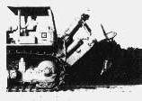
1. Raise lowered equipment high enough to clear obstructions.
2. Depress both brake pedals and release brake lock.
3. Release transmission safety lock.
This is the sample of the manual click on the download link for complete manual
DOWNLOAD LINK
For some reason if link does not work download this pdf and then click