



Product: TRACK-TYPE TRACTOR
Model: D6T TRACK-TYPE TRACTOR LAE
Configuration: D6T TRACK-TYPE TRACTOR STD, XL Differential Steering LAE00001-UP (MACHINE) POWERED BY C9 Engine
Operation and Maintenance Manual
D6T Track-Type Tractor
Media Number -SEBU8146-12
Foreword
Date -01/12/2013 Date Updated -18/03/2019
California Proposition 65 Warning
Diesel engine exhaust and some of its constituents are known to the State of California to cause cancer, birth defects, and other reproductive harm.

WARNING - This product can expose you to chemicals including ethylene glycol, which is known to the State of California to cause birth defects or other reproductive harm. For more information go to:
www.P65Warnings.ca.gov
Do not ingest this chemical. Wash hands after handling to avoid incidental ingestion.
WARNING - This product can expose you to chemicals including lead and lead compounds, which are known to the State of California to cause cancer, birth defects, or other reproductive harm. For more information go to:
www.P65Warnings.ca.gov
Wash hands after handling components that may contain lead.
Literature Information
This manual should be stored in the operator's compartment in the literature holder or seat back literature storage area.
This manual contains safety information, operation instructions, transportation information, lubrication information, and maintenance information.
Some photographs or illustrations in this publication show details or attachments that can be different from your machine. Guards and covers might have been removed for illustrative purposes.
Continuing improvement and advancement of product design might have caused changes to your machine which are not included in this publication. Read, study, and keep this manual with the machine.
Whenever a question arises regarding your machine, or this publication, please consult your Cat dealer for the latest available information.
Safety
The safety section lists basic safety precautions. In addition, this section identifies the text and locations of warning signs and labels used on the machine.
Read and understand the basic precautions listed in the safety section before operating or performing lubrication, maintenance, and repair on this machine.
Operation
The operation section is a reference for the new operator and a refresher for the experienced operator. This section includes a discussion of gauges, switches, machine controls, attachment controls, transportation, and towing information.
Photographs and illustrations guide the operator through correct procedures of checking, starting, operating, and stopping the machine.
Operating techniques outlined in this publication are basic. Skill and techniques develop as the operator gains knowledge of the machine and its capabilities.
Maintenance
The maintenance section is a guide to equipment care. The Maintenance Interval Schedule (MIS) lists the items to be maintained at a specific service interval. Items without specific intervals are listed under the "When Required" service interval. The Maintenance Interval Schedule lists the page number for the step-by-step instructions required to accomplish the scheduled maintenance. Use the Maintenance Interval Schedule as an index or "one safe source" for all maintenance procedures.
Maintenance Intervals
Use the service hour meter to determine servicing intervals. Calendar intervals shown (daily, weekly, monthly, etc.) can be used instead of service hour meter intervals if the calendar intervals
provide more convenient servicing schedules and approximate the indicated service hour meter reading. Perform the recommended service at the interval that occurs first.
Under severe, dusty, or wet operating conditions, more frequent lubrication than is specified in the maintenance intervals chart might be necessary.
Perform service on items at multiples of the original requirement. For example, at every 500 service hours or 3 months, also service those items listed under every 250 service hours or monthly and every 10 service hours or daily.
Certified Engine Maintenance
Proper maintenance and repair are essential to keep the engine and machine systems operating correctly. As the heavy-duty off-road diesel engine owner, you are responsible for the performance of the required maintenance listed in the Owner Manual, Operation and Maintenance Manual, and Service Manual.
It is prohibited for any person engaged in the business of repairing, servicing, selling, leasing, or trading engines or machines to remove, alter, or to render inoperative, any emission-related device or element of design installed on or in an engine or machine that is in compliance with all applicable regulations of the intended country to which it has been shipped. Certain elements of the machine and engine such as the exhaust system, fuel system, electrical system, intake air system, and cooling system may be emission-related and should not be altered unless approved by Caterpillar.
Machine Capacity
Additional attachments or modifications may exceed machine design capacity which can adversely affect performance characteristics. Included would be stability and system certifications such as brakes, steering, and rollover protective structures (ROPS). Contact your Cat dealer for further information.
Product Identification Number
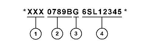
Effective First Quarter 2001 the Product Identification Number (PIN) has changed from 8 to 17 characters. To provide uniform equipment identification, construction equipment manufacturers are moving to comply with the latest version of the product identification numbering standard. Non-road machine PINs are defined by ISO 10261. The new PIN format will apply to all machines and generator sets. The PIN plates and frame marking will display the 17 character PIN. The new format will look like the following:
This is the sample of the manual click on the download link for complete manual
DOWNLOAD LINK
For some reason if link does not work download this pdf and then click
Illustration 1 g03891925
Where:
1. World Manufacturing Code (characters 1-3)
2. Machine Descriptor (characters 4-8)
3. Check Character (character 9)
4. Machine Indicator Section (MIS) or Product Sequence Number (characters 10-17). These were previously referred to as the Serial Number.
Machines and generator sets produced before First Quarter 2001 will maintain their 8 character PIN format.
Components such as engines, transmissions, axles, and work tools will continue to use an 8 character Serial Number (S/N).
Copyright 1993 - 2024 Caterpillar Inc. All Rights Reserved. Private Network For SIS Licensees. Thu Jul 11 11:00:15 UTC+0530 2024

Product: TRACK-TYPE TRACTOR
Model: D6T TRACK-TYPE TRACTOR LAE
Configuration: D6T TRACK-TYPE TRACTOR STD, XL Differential Steering LAE00001-UP (MACHINE) POWERED BY C9 Engine
Operation and Maintenance Manual
D6T Track-Type Tractor
Media Number -SEBU8146-12 Publication Date -01/12/2013 Date Updated -18/03/2019
Angle Blade Manual Tilt Brace - Lubricate
SMCS - 6074-086
If equipped:
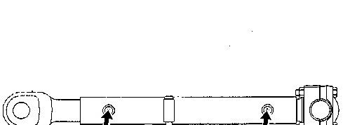
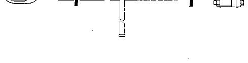
Illustration 1 g00103702
i01034553
Lubricate the two fittings. Use Multipurpose Lithium Complex Grease with Molybdenum (MPGM).
Product: TRACK-TYPE TRACTOR
Model: D6T TRACK-TYPE TRACTOR LAE
Configuration: D6T TRACK-TYPE TRACTOR STD, XL Differential Steering LAE00001-UP (MACHINE) POWERED BY C9 Engine
Operation and Maintenance Manual
D6T Track-Type Tractor
Media Number -SEBU8146-12 Publication Date -01/12/2013 Date Updated -18/03/2019
Backup Alarm - Test
SMCS - 7406-081
The backup alarm is on the rear of the machine.
i02712816
In order to test the alarm for proper functioning, turn the engine start switch to the ON position.
Apply the service brake. Release the parking brake. Move the speed range selector to the REVERSE position.
The backup alarm should start to sound immediately. The backup alarm will continue to sound until the speed range selector is moved to the NEUTRAL position or to the FORWARD position.
Copyright 1993 - 2024 Caterpillar Inc. All Rights Reserved. Private Network For SIS Licensees.
Thu Jul 11 11:23:45 UTC+0530 2024
Product: TRACK-TYPE TRACTOR
Model: D6T TRACK-TYPE TRACTOR LAE
Configuration: D6T TRACK-TYPE TRACTOR STD, XL Differential Steering LAE00001-UP (MACHINE) POWERED BY C9 Engine
Operation and Maintenance Manual
D6T Track-Type Tractor
Media Number -SEBU8146-12
Battery - Inspect
SMCS - 1401-040
Publication Date -01/12/2013 Date Updated -18/03/2019
i01376996
1. Open the battery access covers. The battery access covers are located on the left side of the machine outside the operator compartment.
2. Tighten the battery retainers. Clean the top of the batteries with a clean cloth. Keep the terminals clean and coated with petroleum jelly. Install the terminal covers after you coat the terminals.
3. Close the battery access covers.
Copyright 1993 - 2024 Caterpillar Inc. All Rights Reserved. Private Network For SIS Licensees.
Thu Jul 11 11:23:56 UTC+0530 2024
Product: TRACK-TYPE TRACTOR
Model: D6T TRACK-TYPE TRACTOR LAE
Configuration: D6T TRACK-TYPE TRACTOR STD, XL Differential Steering LAE00001-UP (MACHINE) POWERED BY C9 Engine
Operation and Maintenance Manual
D6T Track-Type Tractor
Media Number -SEBU8146-12 Publication Date -01/12/2013 Date Updated -18/03/2019
i07362441
Belts - Inspect/Adjust/Replace
SMCS - 1357-025; 1357-040; 1357-510
Inspect
1. Open the access door on the right side of the machine. Open the access door on the left side of the machine to inspect the air conditioning compressor belt.
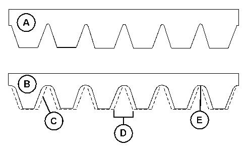
Illustration 1 g06114636
(A) New belt
(B) Worn belt
2. Inspect the condition of the serpentine belts. Over time the belt ribs will lose material (C). The space between the ribs will increase (D). The loss of material will cause the pulley sheave to contact the belt valley. This will lead to belt slippage and accelerated wear (E). Replace the belt if the belt is worn or frayed.
Adjust/Replace
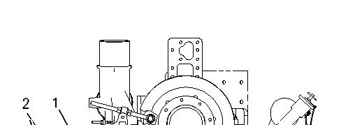
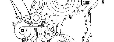
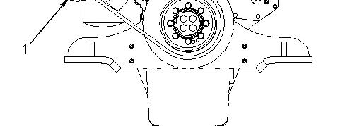

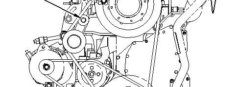
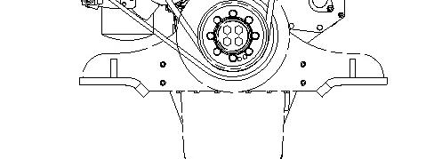
Alternator and Water Pump Belt
2. Turn adjusting nuts (2) until the correct belt tension is reached. To achieve the correct belt adjustment, move the alternator inward or move the alternator outward, as required.
3. Tighten bolts (1).

3
1. Loosen bolts (1).
2. Turn the adjusting nuts (2) until the correct belt tension is reached. To achieve the correct belt adjustment, move the idler pulley inward or move the idler pulley outward, as required.
3. Tighten bolts (1).
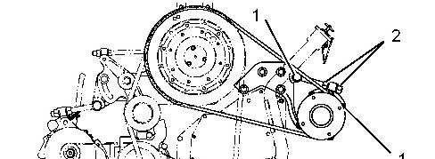
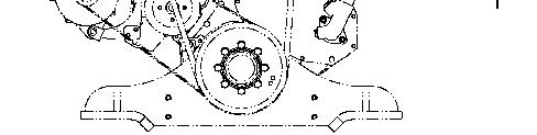
Illustration 4 g01147368
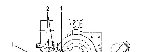
Air conditioning compressor belt
1. Loosen bolts (1).
2. Turn adjusting nuts (2) until the correct belt tension is reached. To achieve the correct belt adjustment, move the compressor inward or move the compressor outward, as required.
3. Tighten bolts (1).
4. Close the access doors.
Note: Use the same procedure to replace the belts.
Note: If new belts are installed, check the belt adjustment again after 30 minutes of engine operation. Copyright 1993 - 2024 Caterpillar Inc. All Rights Reserved. Private Network For SIS Licensees.
Product: TRACK-TYPE TRACTOR
Model: D6T TRACK-TYPE TRACTOR LAE
Configuration: D6T TRACK-TYPE TRACTOR STD, XL Differential Steering LAE00001-UP (MACHINE) POWERED BY C9 Engine
Operation and Maintenance Manual
D6T Track-Type Tractor
Media Number -SEBU8146-12
Publication Date -01/12/2013 Date Updated -18/03/2019
Brakes, Indicators and Gauges - Test
SMCS - 4100-081; 7000-081; 7450-081
Inspect the dash panel for broken lenses, indicator lights, and switches.
CMS Functional Test
To ensure proper operation of the CMS, check the system on a daily basis.
i02431458
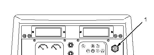
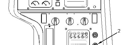

Illustration 1 g01043983
The battery disconnect switch must be ON in order to supply electrical power to the machine so that the electrical systems will function.

ON - The engine start switch key (1) must be turned to the ON position in order to supply electrical power to the operator's compartment so that the CMS will function.
Turn the engine start key to the ON position. The system should act in the following manner:
• The indicator lights on the top portion of the instrument panel come on briefly.
• The action light comes on briefly.
• The auxiliary action light comes on briefly.
• The indicator lights on the bottom portion of the instrument panel flash briefly.
• The action alarm sounds briefly.
• The pointers on the gauges point upward. Then, the pointers point to the left. Then, the pointers point to the right. Then, the pointers point to the final position.
If the system functions properly, start the engine. If any of the following events occur, do not start the engine:
• The indicator lights on the top portion or the bottom portion of the instrument panel do not come on.
• The action light does not come on.
• The auxiliary action light does not come on.
• The action alarm does not sound.
Complete any necessary repairs before you start the engine.

Panel Test Switch
- With the engine stopped, push test switch (2). Service hours will appear in the display area until the switch is pushed. Push the switch and release the switch until the desired information appears in the display area. The following type of information is displayed:
• Total Service Hours
• Service hours in forward speed range
• Service hours in reverse speed range
• Fault codes
Braking System (Test)
If the machine moves during the test, reduce the engine speed immediately, and engage the parking brake.
If the machine moved while testing the brakes, consult your Caterpillar dealer for brake inspection and repair. Damaged brakes must be repaired before returning the machine to operation.
Note: The machine is capable of driving through the brakes in the first speed range.
Make sure that the area around the machine is clear of personnel and clear of obstacles.
Test the brakes on a dry, level surface.
Fasten the seat belt before you test the brakes.
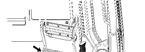
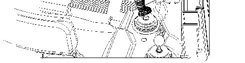
Illustration 2
1. Start the engine.
2. Raise all attachments.
3. Depress the service brake pedal.
4. Release the parking brake.
g01043985
5. While the brake pedal is depressed, move the directional control to the SECOND SPEED FORWARD position.
6. Gradually increase the engine speed to full load speed. The machine should not move.
7. Move the directional control to the NEUTRAL position.
8. Reduce the engine speed to LOW IDLE. Engage the parking brake. Lower all attachments to the ground. Apply a slight down pressure. Stop the engine.
9. Make any necessary repairs before you operate the machine.
NOTICE
If the machine moved while testing the brakes, contact your Caterpillar dealer. Have the dealer inspect and, if necessary, repair the service brake before returning the machine to operation. Copyright 1993 - 2024 Caterpillar Inc. All Rights Reserved. Private Network For SIS Licensees. Thu Jul 11 11:24:28 UTC+0530 2024
Product: TRACK-TYPE TRACTOR
Model: D6T TRACK-TYPE TRACTOR LAE
Configuration: D6T TRACK-TYPE TRACTOR STD, XL Differential Steering LAE00001-UP (MACHINE) POWERED BY C9 Engine
Operation and Maintenance Manual
D6T Track-Type Tractor
Media Number -SEBU8146-12 Publication Date -01/12/2013 Date Updated -18/03/2019
Bulldozer - Lubricate - Variable Pitch Angle Tilt Blade
SMCS - 6050-086
i02627944
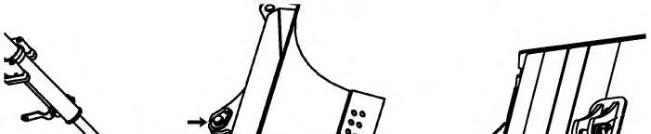
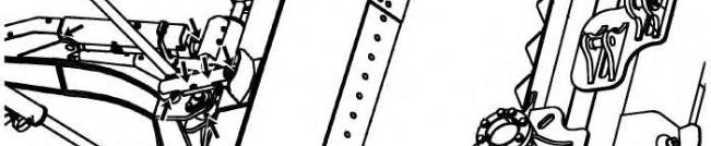
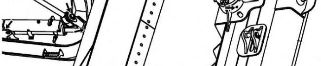

Illustration 1
Lubricate the Variable Pitch Angle Tilt Blade at every 250 hour interval.
1. Lubricate the bearings on the ends of each hydraulic cylinder (6 points).
2. Lubricate the bearings on each end of the stabilizer link (2 points).
3. Lubricate the bearings under the cover of the stabilizer link (2 points).
4. Lubricate the bearings on the rod end of each of the lift cylinders (2 points).
5. Lubricate the trunnion bearing (1 point).
Product: TRACK-TYPE TRACTOR
Model: D6T TRACK-TYPE TRACTOR LAE
Configuration: D6T TRACK-TYPE TRACTOR STD, XL Differential Steering LAE00001-UP (MACHINE) POWERED BY C9 Engine
Operation and Maintenance Manual
D6T Track-Type Tractor
i02276929
Cab Filter (Fresh Air) - Clean/Inspect/Replace - If Equipped
SMCS - 7342-040; 7342-070; 7342-510
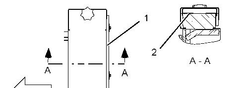

Illustration 1 g01140074
Top view
1. Remove filter cover (1) and filter element (2). The filter cover is in front of the front window of the cab.
2. The filter element can be cleaned by using pressure air. Use a maximum air pressure of 205 kPa (30 psi). Direct the air from the clean side to the dirty side.
3. Look through the filter toward a bright light. Inspect the element for damage. Inspect the gaskets for damage. Replace damaged filters.
4. Install the filter element.
Note: Clean the filters more often in dusty conditions.
Copyright 1993 - 2024 Caterpillar Inc. All Rights Reserved. Private Network For SIS Licensees. Thu Jul 11 11:25:30 UTC+0530 2024
Product: TRACK-TYPE TRACTOR
Model: D6T TRACK-TYPE TRACTOR LAE
Configuration: D6T TRACK-TYPE TRACTOR STD, XL Differential Steering LAE00001-UP (MACHINE) POWERED BY C9 Engine
Operation and Maintenance Manual
D6T Track-Type Tractor
i02277295
Filter (Recirculation) - Clean/Inspect/Replace - If Equipped
SMCS - 7342-040; 7342-070; 7342-510
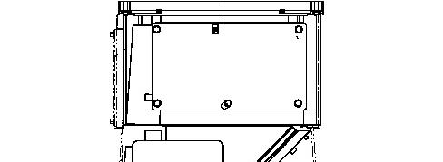

Illustration 1 g01140113
1. Remove the filter element that is positioned in the operator's compartment below the left side of the dash.
2. The filter element can be cleaned by using pressure air. Use a maximum air pressure of 205 kPa (30 psi). Direct the air from the clean side to the dirty side.
3. Look through the filter toward a bright light. Inspect the element for damage. Inspect the gaskets for damage. Replace damaged filters.
4. Install the filter element.
Note: Clean the filters more often in dusty conditions.
1993 - 2024 Caterpillar Inc.
Product: TRACK-TYPE TRACTOR
Model: D6T TRACK-TYPE TRACTOR LAE
Configuration: D6T TRACK-TYPE TRACTOR STD, XL Differential Steering LAE00001-UP (MACHINE) POWERED BY C9 Engine
Operation and Maintenance Manual
D6T Track-Type Tractor Media Number -SEBU8146-12
Camera - Clean/Adjust
SMCS - 7348
Updated -18/03/2019
i03638722
Failure to use an appropriate external ladder or an appropriate platform for direct access to the rear view camera could result in slipping and falling which could result in personal injury or death. Be sure to use an appropriate external ladder or an appropriate platform for direct access to the rear view camera.
The machine's counterweight and the engine hood are not approved as a maintenance platforms.
Unexpected machine movement can cause injury or death.
In order to avoid possible machine movement, move the hydraulic lockout control to the LOCKED position and attach a Special Instruction, SEHS7332, "Do Not Operate" or similar warning tag to the hydraulic lockout control.
When maintenance or servicing of the rear view camera is required follow these steps.
1. Park the machine on a level surface.
2. Place the work tool on the level surface.
3. Move the hydraulic lockout control to the Locked position.
4. Turn the engine start switch to the OFF position and remove the engine start switch key.
5. Turn the battery disconnect switch to theOFF position and remove the battery disconnect switch key.
Clean Camera Lens
If necessary, clean the camera lens before you operate the machine. Use a soft cloth for cleaning.
Adjust the Area of Visibility
If the camera displays an undesired view, adjust the area of the visibility.
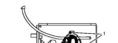

1.
This is the sample of the manual click on the download link for complete manual
DOWNLOAD LINK
For some reason if link does not work download this pdf and then click