
This is the sample of the manual click on the download link for complete manual
DOWNLOAD LINK
For some reason if link does not work download this pdf and then click
4. Install arm assembly (55) and spring (57). Install roller (53) and two spacers. Install retaining ring (52). Install roller (54) and the pin. Install retaining ring (57). Make sure that the rollers do not bind.
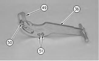
Illustration 4
g00288398
5. Install cam (49) in suspension arm (36). Install retaining rings (51) and (50) and the pins.
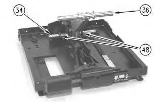
Illustration 5
g00288397
6. Install the shaft and suspension arm (36). Install two spacers (48) on shaft (34).
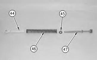
Illustration 6
g00288396
7. Assemble the spring assembly. Install rod assembly (47), retainer (45), spring (46), and guide bushing (44).
7
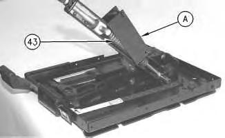
8. Attach Tool (A) to spring assembly (43), as shown. Slowly compress spring assembly (43). Use Tool (A) to install the spring assembly on the shaft as a unit.
9. Repeat Steps 7 and 8 for the spring assembly on the other side of the suspension arm.
8
9
Note: Apply Tooling (B) to the roller shafts before installation.
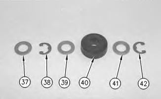
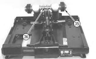
10. Install retaining rings (42) and (38), washers (41), (39) and (37), and rollers (40). Install roller assembly (35) on each side of suspension arm (36). Make sure that the rollers do not bind.
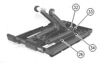
Illustration 10
g00288370
11. Install two springs (26) and plastic bearings (32) on height adjustment shaft (34). Install retaining ring (33) on each side of height adjustment shaft (34).
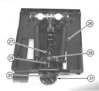
Illustration 11
g00288369
12. Install nut (28), weight adjustment screw (29), two races, the thrust bearing, weight adjustment knob (31) and pin (30). Turn weight adjustment knob (25) in the positive (+) direction to apply tension to springs (26). Install pin (27) in the end of weight adjustment screw (29).
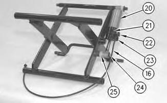
Illustration 12
g00288368
Note: During removal of the wire cable, the wire cable will be cut. The wire cable will not be reusable. A new wire cable must be installed during assembly of the mechanical suspension.
13. Install variable damper (20), retainer (24), two bearings (25), bracket (23) and arm (22). Install new adjustable bracket (21). Install the pin in arm (22). Install a new wire cable in the variable damper. Connect wire cable (16) to bracket (23).
Note: Adjustable bracket (21) must be replaced. The bracket will be damaged during the removal procedure.
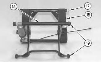
Illustration 13
g00288367
Note: Apply Tooling (B) to the roller shafts before installation.
14. Install four rollers (19), two tether belts (18) and four bearings (17). Make sure that the rollers do not bind.
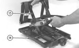
Illustration 14
g00288365
15. Install scissor assembly (13) on upper housing (14).
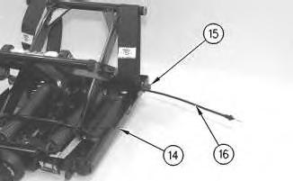
Illustration 15
g00288364
16. Slide wire cable (16) into upper housing (14). Install the upper shaft assembly. Install locknut (15) on the upper shaft assembly.
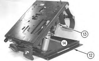
Illustration 16
g00288363
17. Install the tie-wraps to hold the adjustable cable to upper housing (14). Tilt the lower housing forward and slide the lower housing onto scissor assembly (13) and onto upper housing (14).
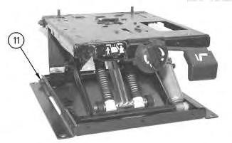
Illustration 17
g00288362
18. Install the lower shaft assembly. Install locknut (11).
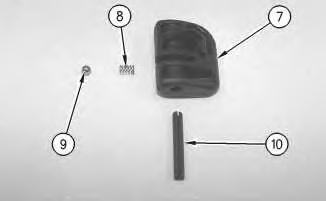
Illustration 18
g00288361
19. Install ball (9), spring (8), and knob (7). Install pin (10).
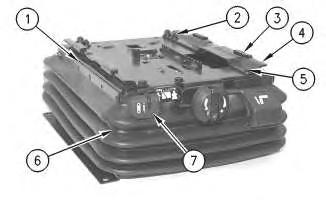
Illustration 19
20. Install two retainers (1) and boot (6).
g00288360
21. Install two brackets (4), the locknuts on two brackets (4), the washers, two bolts (5) and four bolts (2). Tighten the bolts to a torque of 25 ± 6 N·m (18 ± 4 lb ft). Install four slider blocks (3).
Copyright 1993 - 2024 Caterpillar Inc. All Rights Reserved. Private Network For SIS Licensees.
Sat Mar 9 09:45:01 UTC+0530 2024

Product: TRACK-TYPE TRACTOR
Model: D6R TRACK-TYPE TRACTOR 7DR
Configuration: D6R TRACTORS / POWERSHIFT / 7DR00001-UP (MACHINE) POWERED BY 3306 ENGINE
Disassembly and Assembly
Comfort Series Seat For Caterpillar Machines
Media Number -RENR2165-12
Mechanical Suspension With Variable Damper - Disassemble
SMCS - 7324-015-ME
Disassembly Procedure Table 1
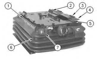
Illustration 1
2
1. Remove four slider blocks (3). Remove four bolts (2), two bolts (5), the washers, and the locknuts from two brackets (4).
2. Remove boot (6) and two retainers (1). Use a hammer and a punch to remove pin (10). Remove knob (7), spring (8) and ball (9).
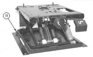
3
3. Remove locknut (11). Remove the lower shaft assembly.
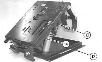
4
4. Lift up lower housing (12). Tilt the lower housing forward in order to remove the lower housing from scissor assembly (13) and from upper housing (14). Remove the tie-wraps that are holding the adjustable cable to upper housing (14).
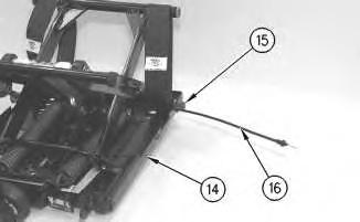
Illustration 5
g00288364
5. Remove locknut (15) from the upper shaft assembly. Remove the upper shaft assembly. Slide wire cable (16) from upper housing (14).
Illustration 6
g00288365
6. Lift up scissor assembly (13). Tilt the scissor assembly forward and remove the scissor assembly from upper housing (14).
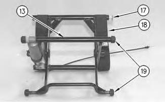
Illustration 7
7. Remove two tether belts (18), four rollers (19) and four bearings (17) from scissor assembly (13).
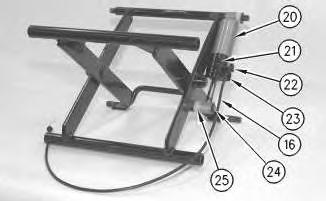
Illustration 8
g00288368
Note: During removal of the wire cable, the wire cable will be cut. The wire cable will not be reusable. A new wire cable must be installed during assembly of the mechanical suspension.
8. Cut wire cable (16) at the point of connection to bracket (23). Remove the wire cable from the variable damper. Use a hammer and a punch to remove the pin from arm (22). Remove adjustable bracket (21). Remove arm (22), bracket (23), two bearings (25), retainer (24) and variable damper (20).
Note: Adjustable bracket (21) must be replaced. The bracket will be damaged during the removal procedure.
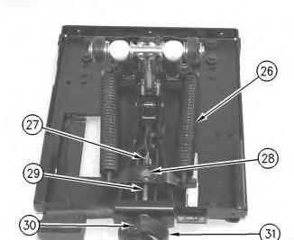
Illustration 9
g00288369
9. Remove pin (27) from the end of weight adjustment screw (29). Turn weight adjustment Remove pin (30), weight adjustment knob (31), the thrust bearing, two races, weight adjustment screw (29) and nut (28).
10
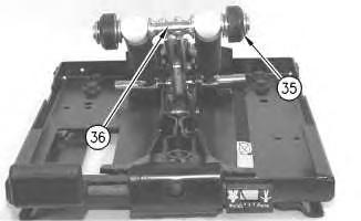
10. Remove retaining ring (33) from each side of height adjustment shaft (34). Remove two springs (26) and plastic bearings (32) from height adjustment shaft (34).
11
12
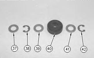
11. Remove roller assembly (35) from each side of suspension arm (36). Remove retaining rings (42) and (38), washers (41), (39) and (37), and rollers (40).
Illustration 13
g00288375
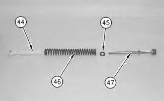
Illustration 14
g00288396
12. Attach Tool (A) to spring assembly (43), as shown. Use Tool (A) to remove the spring assembly from the shaft as a unit.
13. Use Tool (A) to slowly release the compression on spring assembly (43). Disassemble spring assembly (43). Remove guide bushing (44), spring (46), retainer (45) and rod assembly (47).
14. Repeat Steps 12 and 13 for the spring assembly on the other side of the suspension arm.
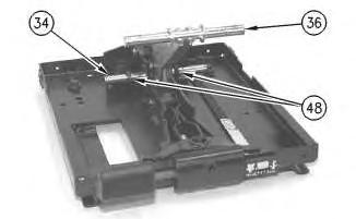
Illustration 15
g00288397
15. Remove two spacers (48) from shaft (34). Remove the shaft and suspension arm (36).
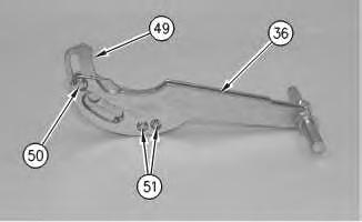
Illustration 16
g00288398
16. Remove retaining rings (50) and (51). Use a hammer and a punch to remove the pins. Remove cam (49) from suspension arm (36).
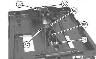
Illustration 17
g00288399
17. Remove retaining ring (57). Use a hammer and a punch to remove the pin. Remove roller (54). Remove retaining ring (52). Use a hammer and a punch to remove the pin. Remove roller (53) and two spacers. Remove spring (56) and arm assembly (55).
18
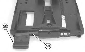
18. Remove the key for the height adjustment lever. (The key is not shown.) Remove handle (58) and height adjustment lever (59).
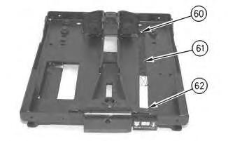
Illustration 19
g00288401
19. Remove pin (62) from the bracket. Cut tie-wraps (60). Remove indicator band (61).
Copyright 1993 - 2024 Caterpillar Inc. All Rights Reserved. Private Network For SIS Licensees.
Sat Mar 9 09:43:56 UTC+0530 2024
Product: TRACK-TYPE TRACTOR
Model: D6R TRACK-TYPE TRACTOR 7DR
Configuration: D6R TRACTORS / POWERSHIFT / 7DR00001-UP (MACHINE) POWERED BY 3306 ENGINE
Disassembly and Assembly
Comfort Series Seat For Caterpillar Machines
Media Number -RENR2165-12
Date -01/10/2013 Date Updated -31/10/2013
Mechanical Suspension With Fixed Damper - Assemble
SMCS - 7324-016-ME
Assembly Procedure
Table 1 Tools Needed
- Loctite LB 8632 Silicone Lubricant (1)
- Loctite LB 8104 Silicone Lubricant (2)
- Loctite LB 8801 Silicone Lubricant (3)
- Loctite LB Superlube (4)
(1) North America (2) EAME (3) Asia Pacific Division (4) South America
i07432498
1. Check the condition of all parts of the mechanical suspension. If any of the parts are worn or damaged, install new parts.
1
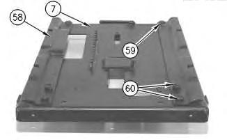
2. Install two brackets (58) on upper housing (7). Install the washers, four bolts (60), two bolts (59), and the locknuts on two brackets (58). Tighten the bolts to a torque of 25 ± 6 N·m (18 ± 4 lb ft).
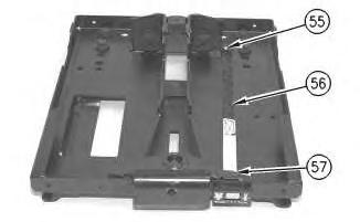
Illustration 2
3. Install indicator band (56) and new tie-wraps (55). Install pin (57) in the bracket.
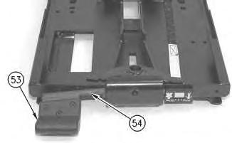
Illustration 3
4. Install height adjustment lever (54) and handle (53). Install the key for the height adjustment lever.
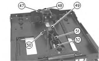
Illustration 4
Note: Apply Tooling (B) to the roller shafts before installation.
5. Install arm assembly (51) and spring (52). Install roller (48), two spacers, and the pin. Install retaining ring (47). Install roller (49) and the pin. Install retaining ring (50). Make sure that the rollers do not bind.
5
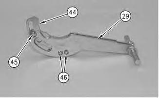
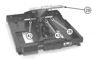
6. Install cam (44) in suspension arm (29). Install retaining rings (45) and (46) and the pins.
6
7. Install the shaft and suspension arm (29). Install spacers (42) and (43) on shaft (28).
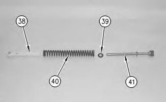
Illustration 7
g00288350
8. Install rod assembly (41), retainer (39), spring (40), and guide bushing (38). Assemble spring assembly (37).
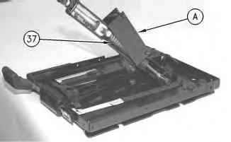
Illustration 8
g00288349
9. Attach Tool (A) to spring assembly (37), as shown. Slowly compress spring assembly (37). Use Tool (A) to install the spring assembly on the shaft.
10. Repeat Steps 8 and 9 for the spring assembly on the other side of the suspension arm.
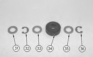
Illustration 9
g00288348
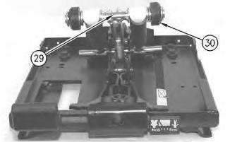
Illustration 10
g00288346
Note: Apply Tooling (B) to the roller shafts before installation.
11. Install retaining rings (32) and (36), washers (31), (33) and (35), and rollers (34). Install roller assembly (30) on each side of suspension arm (29). Make sure that the rollers do not bind.
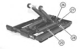
Illustration 11
g00288345
12. Install two springs (20) and plastic bearings (26) on height adjustment shaft (28). Install retaining ring (27) on each side of height adjustment shaft (28).
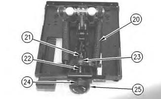
Illustration 12
g00288344
13. Install nut (23), weight adjustment screw (22), two races, the thrust bearing, weight adjustment knob (25) and pin (24). Turn weight adjustment knob (25) in the positive (+) direction to apply tension to springs (20). Install pin (21) in the end of weight adjustment screw (22).
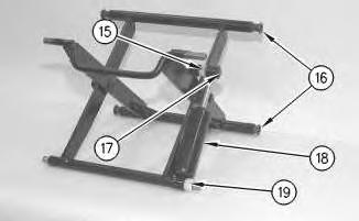
Illustration 13
g00288343
14. Install damper (18), two bearings (15) and (19), and retainer (17). Install four bearings (16).
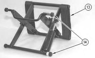
Illustration 14
g00288340
Note: Apply Tooling (B) to the roller shafts before installation.
15. Install four rollers (14) and two tether belts (13). Make sure that the rollers do not bind.
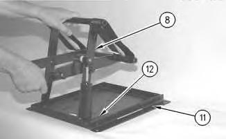
15
16. Install scissor assembly (8) on lower housing (11). Slide the scissor assembly into slider track (12).
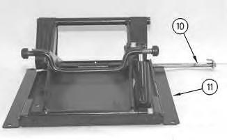
Illustration 16
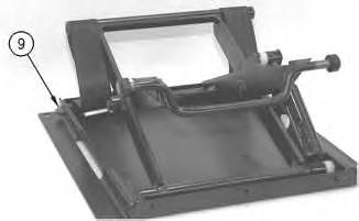
Illustration 17
17. Install lower shaft assembly (10) in lower housing (11). Install locknut (9) on lower shaft assembly (10).
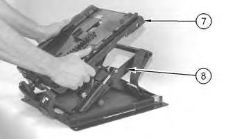
Illustration 18
g00288295
18. Tip upper housing (7) forward and slide the upper housing onto scissor assembly (8).
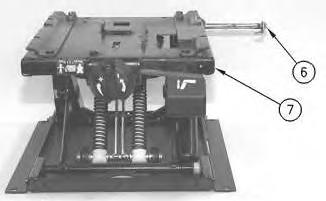
Illustration 19
g00288294
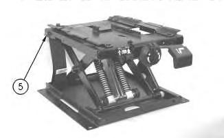
Illustration 20
g00288293
19. Install upper shaft assembly (6) in upper housing (7). Install locknut (5).
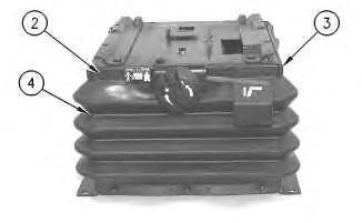
Illustration 21
g00288292
20. Remove fasteners (2). Install boot (4) and two retainers (3).
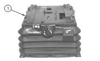
Illustration 22
21. Install four slider blocks (1).
Copyright 1993 - 2024 Caterpillar Inc. All Rights Reserved. Private Network For SIS Licensees.
g00288290
Sat Mar 9 09:43:25 UTC+0530 2024
This is the sample of the manual click on the download link for complete manual
DOWNLOAD LINK
For some reason if link does not work download this pdf and then click