D6N TRACK-TYPE TRACTOR
Product: TRACK-TYPE TRACTOR
Model: D6N TRACK-TYPE TRACTOR ALH
Configuration: D6N XL, FTC, LGP TRACK-TYPE TRACTOR ALH00001-UP (MACHINE) POWERED BY 3126B Engine
Operation and Maintenance Manual
OPERATION & PREVENTIVE MAINTENANCE MANUAL WINCH MODEL PA56 W
Media Number -SEBU7048-00 Publication Date -01/08/1996 Date Updated -25/09/2009
General Safety Recommendations
Safety for operators and ground personnel is of prime concern. Always take the necessary precautions to ensure safety to others as well as yourself. To ensure safety, the tractor and winch must be operated with care, concern by the operator for the equipment and a thorough knowledge of the machine's performance capabilities. The following recommendations are offered as a general safety guide. Local rules and regulations will also apply.
FAILURE TO OBEY THE FOLLOWING SAFETY RECOMMENDATIONS MAY RESULT IN PROPERTY DAMAGE, INJURY OR DEATH.
1. Read all warning tag information and become familiar with all controls BEFORE operating winch.
2. Never attempt to clean, oil or perform any maintenance on a machine with the engine running, unless instructed to do so in the Service Manual.
3. Before starting tractor, be certain all controls move freely and are placed in the "BrakeOn" (neutral) position.
4. Never operate winch controls unless you are properly seated at the operators station on the tractor and you are sure personnel are clear of work area.
5. Operate winch line speeds to match job conditions.
6. Assure that personnel who are responsible for hand signals are clearly visible and that the signals to be used are thoroughly understood by everyone.
7. Never attempt to handle winch cable when the hook end is not free.
8. Leather gloves should be used when handling winch cable.
9. Ground personnel should stay in view of tractor operator and clear of winch drum. Do not allow ground personnel near winch line under tension. A safe distance of at least 1 1/2 times the length of the cable in use should be maintained.
10. When winding cable on the winch drum, never attempt to maintain tension by allowing cable to slip through hands. Always use "hand-over-hand" method.
11. Use correct size ferrule for cable and pocket in winch drum. Never use knots to secure or attach cable.
12. Inspect rigging, winch and tractor at the beginning of each work shift. Any cable with broken strands or rigging worn or damaged should be replaced.
13. Position tractor for straightest line of pull. Use fairlead if side pulls are frequently encountered.
14. The cable anchor or ferrule pocket in the cable drum is designed to provide a self release in the event a back-sliding load must be released from the tractor in an emergency situation. The cable anchor or ferrule alone will NOT support rated linepull. Therefore, a minimum of five (5) complete wraps of cable must be maintained on winch drum.
15. Be sure of tractor ground stability before winching in load.
16. Store unused chokers, slings and rigging in a neat and orderly fashion to prevent damage to equipment or injury to personnel.
17. The maximum rated bare drum line pull of the PA56 is 89,800 lb (399.4 kN)** . Do not operate the winch under loads that exceed the maximum rated bare drum line pull. If excessive loads are encountered, use a multi-part line and sheave blocks. any attempt to exceed the capabilities of one winch (such as coupling 2 or more tractors together) is extremely hazardous.
**Breaking strength of 1 in. (25 mm) EIPS wire rope.
18. The factory approved adaptions for Paccar winches are designed and intended for use on specific models of crawler tractors. Changing winches between tractors is not possible in some cases because of differences in tractor models. Some changes cannot be approved by Paccar winch because of safety limitations. Call a Paccar winch dealer or the Factory prior to attempting winch modifications or before mounting on a different tractor.
19. Paccar power shift winches are equipped with hydraulic accumulators. Discharge the accumulator stored oil supply before removing any hydraulic lines or fittings or servicing winch. Personal injury may result from the sudden release of oil pressure. To discharge the accumulator, stop the engine, slowly cycle the Power Shift control handle into full Haul-In then Pay-Out positions a minimum of five (5) times.
20. On machines having hydraulically, mechanically and/or cable controlled equipment, be certain the equipment is either lowered to the ground or blocked securely before servicing, adjusting and/or repairing the winch. Always apply tractor parking brakes and lower equipment before dismounting the tractor.
Copyright 1993 - 2025 Caterpillar Inc. All Rights Reserved.
Network For SIS Licensees. Tue Jan 14 22:20:28 UTC+0530 2025
Product: TRACK-TYPE TRACTOR
Model: D6N TRACK-TYPE TRACTOR ALH
Configuration: D6N XL, FTC, LGP TRACK-TYPE TRACTOR ALH00001-UP (MACHINE) POWERED BY 3126B Engine
Operation and Maintenance Manual
OPERATION & PREVENTIVE MAINTENANCE MANUAL WINCH MODEL PA56 W
Media Number -SEBU7048-00
Model Description
Publication Date -01/08/1996
Date Updated -25/09/2009
The Paccar Power Shift Winch is a single drum unit which mounts on the rear of a crawler tractor. It is driven by engine power through the tractor PTO (Power Take-Off). The winch may be operated independently or with the tractor transmission engaged. When operated properly, it is capable of utilizing maximum engine horse-power. The winch has equal speed gearing, power-in and power-out, using multiple-disc oil actuated friction clutches and a spring applied hydraulically released multiple-disc oil brake.
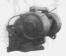
The winch may be manufactured as a Standard PTO or Low PTO configuration, depending on tractor application. In the Standard PTO configuration, the bevel gear group, clutch and brake components are located in the upper bores of the winch case.
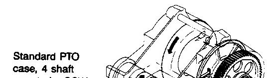
Standard PTO Shown
The Low PTO winch design has the bevel gear group, clutch and brake components located in the lower bores of the winch case.
All PA56 series winches are 4-shaft configuration.
Standard and Low PTO configurations are available as either a standard or slow speed. The standard speed winch is primarily used in logging, land clearing and general utility applications. The standard speed model has gear ratios which match the cable drum rotation in Haul-In (forward) to reverse track speeds for optimum advantage in tractor recovery.
The slow speed configuration is similar to the standard speed but uses slow speed gearing for greater load control. The slow speed configuration is well suited to oil and gas field, mining and pipeline applications.
This is the sample of the manual click on the download link for complete manual
DOWNLOAD LINK
For some reason if link does not work download this pdf and then click
Optional features increase the winches ability to meet specific application requirements. Options available for the PA56 series winches include:
- Free Spool
- Gear Ratios
- Three or Four Roller Fairleads
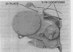
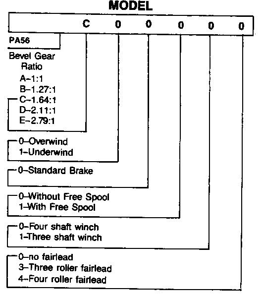
The winch model number is an important reference as to what optional components were used when the winch was manufactured. The winch identification plate is located on the right hand side of the winch case. The serial number is also stamped into the upper right hand mounting pad.
The winch model number contains the following configuration data:
Important: Always refer to the serial number and model number when requesting information or service parts.
Copyright 1993 - 2025 Caterpillar Inc. All Rights Reserved. Private Network For SIS Licensees.
Tue Jan 14 22:20:54 UTC+0530 2025
Product: TRACK-TYPE TRACTOR
Model: D6N TRACK-TYPE TRACTOR ALH
Configuration: D6N XL, FTC, LGP TRACK-TYPE TRACTOR ALH00001-UP (MACHINE) POWERED BY 3126B Engine
Operation and Maintenance Manual
OPERATION & PREVENTIVE MAINTENANCE MANUAL WINCH MODEL PA56 W
Media Number -SEBU7048-00
Publication Date -01/08/1996 Date Updated -25/09/2009
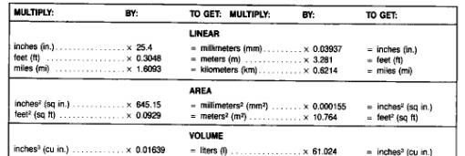
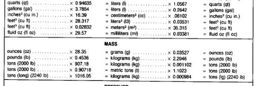
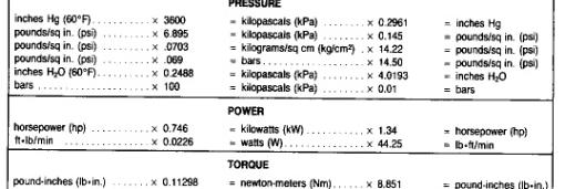
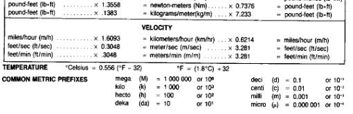
Metric Conversion Table
Copyright 1993 - 2025 Caterpillar Inc.
Rights Reserved.
Network For SIS Licensees.
Tue Jan 14 22:22:54 UTC+0530 2025
Product: TRACK-TYPE TRACTOR
Model: D6N TRACK-TYPE TRACTOR ALH
Configuration: D6N XL, FTC, LGP TRACK-TYPE TRACTOR ALH00001-UP (MACHINE) POWERED BY 3126B Engine
Operation and Maintenance Manual
OPERATION & PREVENTIVE MAINTENANCE MANUAL WINCH MODEL PA56 W
Media Number -SEBU7048-00
Publication Date -01/08/1996
Preventive Maintenance & Specifications
Date Updated -25/09/2009
A regular program of preventive maintenance for your Paccar winch will minimize the need for emergency servicing and promote long product life and trouble-free service.
The service intervals suggested in this manual will optimize component service life. The intervals may be gradually increased or decreased with experience of a particular lubricant and evaluation of your application.
NOTICE
Discharge accumulator oil supply before removing any hydraulic lines or servicing winch. Personal injury may result from sudden release of oil pressure. To discharge accumulator, stop engine, slowly cycle Power Shift control handle into full Reel-In then Reel-Out positions a minimum of five (5) times. The tractor master switch and ignition must be ON.
1. Oil Level
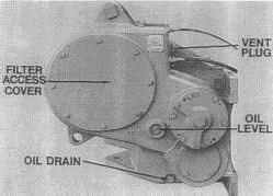
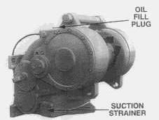
Check oil level at the beginning of each work shift, with tractor and winch in level position. Oil must be visible in the upper half of the sight gauge. If an oil level plug is used in place of the sight gauge, the oil level should be at the bottom of the level plug hole. Add oil as required through the fill plug at top of winch case.
2. Oil Change, Filter and Strainer Service
Under normal operating conditions, the oil and pressure circuit filter should be changed and suction strainer cleaned after the first 100-250 hours of operation, then every 1000 hours or six months, whichever occurs first, or when the filter bypass indicator light remains on after initial warm up.
Hot oil may cause injury. Make certain oil has cooled to a safe temperature before servicing.
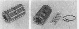
To drain oil, place tractor and winch in level position and remove drain plug located at lower right hand side of winch case. Drain oil into a suitable container and recycle or dispose of used oil in an environmentally responsible manner. Install plug securely after oil has been drained. After oil has drained, remove four suction strainer cover capscrews and cover. Remove suction strainer from winch case then remove metal band and magnetic rods from suction strainer. Thoroughly wash strainer in clean safety solvent and blow dry with compressed air, inspect wire mesh for damage or clogging with debris. Do not reuse a damaged suction strainer.
Install magnetic rods onto suction strainer using metal band. Lubricate o-ring and install strainer spring and cover into winch case.
Refill winch to proper level with recommended oil.
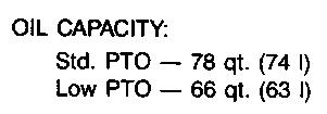
OIL CAPACITY:
Std. PTO - 78 qt. (74 I)
NOTICE
To prevent serious damage to winch, do not run engine while oil is drained from winch.
The pressure filter is located behind the right hand, eight-bolt access cover. Remove the cover, locate the spin-on pressure filter and remove the filter element with a strap wrench.
Lubricate the filter gasket and adapter threads with hydraulic oil and install new filter element onto filter head. Tighten 1/2 - 3/4 turn after seal ring makes cont with filter head.
Start tractor and operate engine at low idle. Correct any leaks.
The indicator light may come on for a short time during initial cold start-up but should go out as the oil warms up. If the light stays on, this indicates a restricted filter element, sending unit stuck in the bypass position or accidentally grounded sending unit wire.
3. Vent Plug
The vent is located next to the electrical connector. It is very important to keep this vent clean and unobstructed. Whenever the oil is changed, remove vent plug, clean in safety solvent and reinstall. Do not replace with a solid plug.
4. Winch Cable (wire rope)
Inspect entire length of wire rope, chokers and hooks according to wire rope and rigging manufacturers recommendations.
5. Mounting Fasteners
Check/tighten all winch mounting fasteners to recommended torque after the first 100-250 hours of operation, then every 1000 operating hours or six (6) months, whichever occurs first.
6. Warm-Up Procedure
A warm-up procedure is recommended at each start-up and is essential at ambient temperatures below +40°F (4°C). Failure to warm-up winch hydraulic system may result in erratic clutch/brake operation which may result in property damage, personal injury or death.
Start tractor engine and operate at low idle for five minutes.
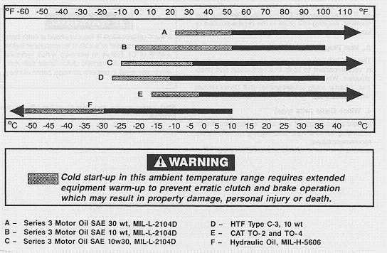
Recommended Oil
We have published the following specification to help you determine which lubricant is best suited to your application. Your lubricant supplier should assure you that his product meets this specification. If there is still any doubt as to the suitability of a lubricant, contact the Paccar Winch Service Department, providing a detailed copy of the product specifications.
Prevailing Ambient Temperature
Cold start-up in this ambient temperature range requires extended equipment warm-up to prevent erratic clutch and brake operation which may result in property damage, personal injury or death.
A - Series 3 Motor Oil SAE 30 wt, MIL-L-2104D
C - Series 3 Motor Oil SAE 10w30, MIL-L-2104D
D - HTF Type C-3, 10 wt
E - CAT TO-2 and TO-4
F - Hydraulic Oil, MIL-H-5606
Basic Oil Requirements
20 000 SUS maximum allowed viscosity at cold start-up; requires extended equipment warm-up. 3,500 SUS maximum allowed viscosity at cold start-up; requires normal equipment warm-up. 60
B - Series 3 Motor Oil SAE 10 wt, MIL-L-2104D
SUS minimum allowed viscosity at maximum winch operating temperature assuming ambient plus 80°F (27°C).
Oil must possess high temperature oxidation stability, rust and corrosion protection, good dispersant and detergent characteristics, anti-wear additives and remain compatible with nitrile base seals.
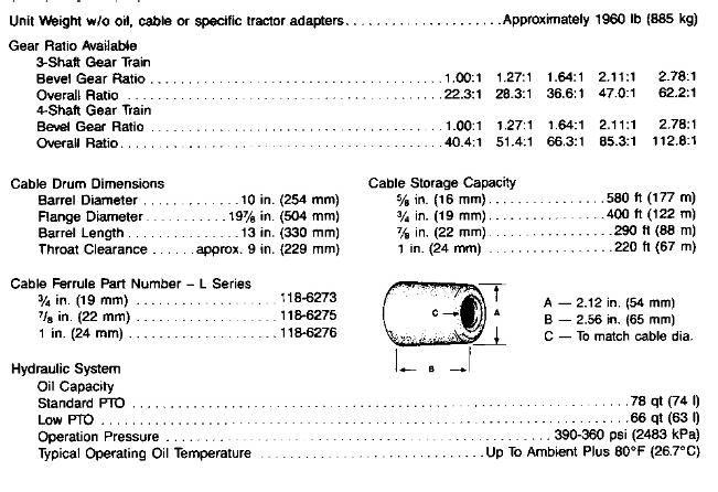
Specifications
Unit Weight w/o oil, cable or specific tractor adapters ... Approximately1960 lb(885 kg)
Gear Ratio Available
3-Shaft Gear Train
4-Shaft Gear Train
Cable Drum Dimensions
Barrel Diameter ... 10 in.(254 mm)
Flange Diameter ... 19 7/8 in.(504 mm)
Barrel Length ... 13 in.(330 mm)
Throat Clearance ... approx. 9 in.(229 mm)
Cable Storage Capacity
5/8 in. (16 mm) ... 580 ft(177 m)
3/4 in. (19 mm) ... 400 ft(122 m)
7/8 in. (22 mm) ... 290 ft(88 m)
1 in. (24 mm) ... 220 ft(67 m)
Cable Ferrule Part Number - L Series
3/4 in. (19 mm) ... 118-6273
7/8 in. (22 mm) ... 118-6275
1 in. (24 mm) ... 118-6276
Hydraulic System
Oil Capacity
Standard PTO ... 78 qt(74 l)
Low PTO ... 66 qt(63 l)
Operation Pressure ... 390-360 psi(2483 kPa)
Typical Operating Oil Temperature ... Up To Ambient Plus 80°F(26.7°C)
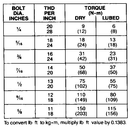
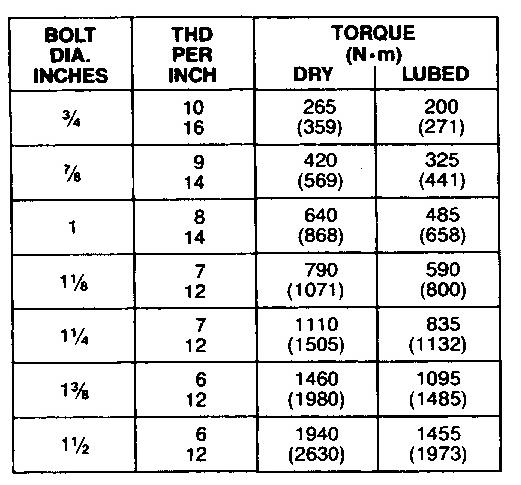
Recommended Fastener Torque
The general purpose torque shown in the chart applies to SAE Grade 5 bolts, studs and standard steel full, thick and high nuts.
Higher or lower torques for special applications will be specified such as the use of spanner nuts, nuts on shaft ends, jam nuts and where distortion of parts or gaskets is critical.
Lubricated Torque values based on use of SAE 30wt engine oil applied to threads and face of bolt or nut.
Avoid using thread lubricants as the applied torque may vary by 10-40% depending upon product used.
Product: TRACK-TYPE TRACTOR
Model: D6N TRACK-TYPE TRACTOR ALH
Configuration: D6N XL, FTC, LGP TRACK-TYPE TRACTOR ALH00001-UP (MACHINE) POWERED BY 3126B Engine
Operation and Maintenance Manual
OPERATION & PREVENTIVE MAINTENANCE MANUAL WINCH MODEL PA56 W
Media Number -SEBU7048-00
Control Operation
Publication Date -01/08/1996
Date Updated -25/09/2009
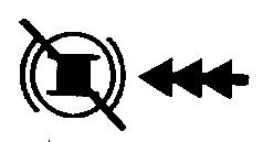
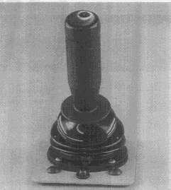
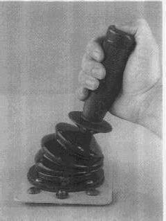
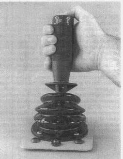
Two actions are required to initiate winch operation. First, the button on top of the control lever must be depressed; next, the lever must be moved in one of four axis to select a winch function. Movement of the lever without depressing the button will NOT result in winch function; this is intended to prevent inadvertent winch operation. The winch functions which may be selected with the lever are Haul-In (forward), Pay-Out (reverse), Brake-Off, and Freespool; the spring centered, neutral position of the lever is Brake-On. Note that it is not possible to control cable drum speed ("feather") in the Haul-In and Pay-Out functions with the control lever. The speed of cable drum rotation must be controlled by varying the tractor engine rpm. Sufficient hydraulic pressure will be available to fully apply the clutches at engine (PTO) speeds above low idle. If the winch is mounted on a direct drive tractor, the tractor master clutch MUST be engaged BEFORE moving the power shift lever. The internal winch pump is only driven when the PTO shaft is turning. A continuous oil supply is needed to provide reliable clutch and brake operation.
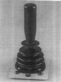

Brake-On (neutral). Control lever is spring centered to Brake-On. Brake is applied by spring force. Cable drum and load is held secure by spring applied brake.
Haul-In (forward). Control lever is moved forward to fully engaged position. Brake is hydraulically released and Haul-In (forward) clutch is hydraulically applied.
Brake-Off. The brake is hydraulically released by moving the control lever toward the operator. Partial brake release may be achieved by slowly moving the control lever into the gate. The amount of brake release is proportional to the distance the lever moves into the gate.
Full brake release is achieved by moving the lever fully toward the operator into the lock position. With the brake released, the tractor may walk away from the load. Always return the control lever to Brake-On (neutral) position.
Pay-Out (reverse). Control lever is moved toward the rear of the tractor to fully engaged position. Brake is hydraulically released and Pay-Out (reverse) clutch is hydraulically applied.
Free Spool Control Operation
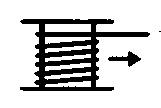
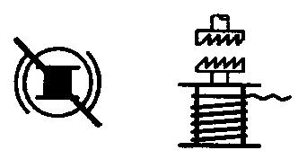
When freespool is selected, drum drive gears are disengaged, allowing wire rope to easily be pulled off by hand. Brake is automatically released when freespool is selected. Note that the freespool function is used for handling wire rope by hand ONLY. Do not attempt to release a load with freespool or reengage the gear train while the drum is rotating or while the vehicle is in motion.
NOTICE
1. Do not shift freespool lever and attempt to engage cable drum while the cable drum or gear train is rotating. Winch gear train damage may result.
2. Never attempt to disengage freespool under load. Damage to freespool components may occur.
3. Remove load from line with brake-off function prior to selecting freespool.
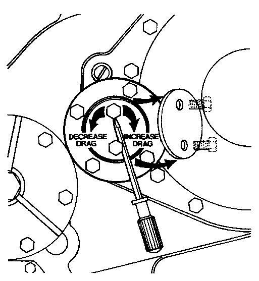
Using a long screw driver or pry bar, turn the threaded adjuster clockwise until tight. Then back off up to 1/4turn maximum and secure with lock plate and capscrews. Tighten capscrews to 75 lb·ft (102 N·m) torque.
NOTE: Tightening the threaded adjuster pushes the tapered bearing cup (outer race) into closer contact with the bearing cone and increases the bearing drag; much like tightening a wheel bearing nut on an automobile or truck. The snug fitting bearing cup will NOT move outward with the threaded adjuster when the adjuster is loosened. The winch must be operated under load for a brief period to allow the gear train load to push the outer bearing cup out against the threaded adjuster before a reduction in bearing drag can be noticed.
NOTICE
Do not back off adjuster more than 1/4 turn as this allows excessive shaft end play and may cause gear train misalignment, accelerated wear and noise.
Product: TRACK-TYPE TRACTOR
Model: D6N TRACK-TYPE TRACTOR ALH
Configuration: D6N XL, FTC, LGP TRACK-TYPE TRACTOR ALH00001-UP (MACHINE) POWERED BY 3126B Engine
Operation and Maintenance Manual
OPERATION & PREVENTIVE MAINTENANCE MANUAL WINCH MODEL PA56 W
Media Number -SEBU7048-00
Winch Operation
Hydraulic System
Publication Date -01/08/1996
Date Updated -25/09/2009
The winch contains an independent, internal hydraulic system. The winch housing serves as a reservoir and stores filtered oil for the internally mounted hydraulic pump. The pump is driven by a gear pressed onto the bevel pinion gear. The pump supplies oil whenever the PTO shaft is turning. Oil from the pump is routed through a pressure filter then directed to the control valve where a stand by system pressure is maintained at 360 psi (2486 kPa).
The system oil pressure is routed through the control valve body to the reel-in, reel-out, brake, and freespool solenoid cartridges. Signals from the control section of the winch actuate the solenoids, resulting in winch function.
The winch hydraulic system is equipped with an accumulator. The accumulator stores a small amount of oil at system pressure to assist the application of clutches and release of the brake under all operating conditions.
The stored oil supply may also be used to release the spring applied brake whenever the tractor engine or torque converter is stalled. The accumulator stored oil is continuously refilled by the winch pump and valve whenever the PTO shaft is turning.
On tractors which supply PTO power through the torque converter, it is possible to cause the torque converter to stall if the tractor engine speed is too low. It is important that engine idle be set to factory specifications.
NOTICE
Discharge accumulator oil supply before removing any hydraulic lines or servicing winch. Personal injury may result from sudden release of oil pressure. To discharge accumulator, stop engine, slowly cycle Power Shift control handle into full Reel-In then Reel-Out positions a minimum of five (5) times. The tractor master switch and ignition must be ON.
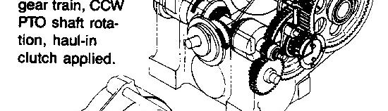
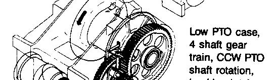
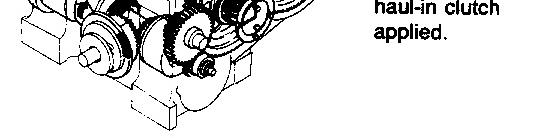
The winch bevel pinion, bevel gears, hydraulic pump and clutch friction discs are rotating whenever the tractor PTO shaft is rotating. Application of a clutch, Haul-In or Pay-Out, and the simultaneous release of the brake will cause the rotation of the remaining gear train and cable drum. See illustrations below.
The clutch shaft assembly (with bevel gears) must turn 40.4 times for one (1) rotation of the cable drum on a 4 shaft gear train winch and 22.3 times on a 3 shaft gear train winch.
The direction of the tractor PTO shaft rotation and the right and left hand clutch location is determined by facing the rear of the tractor.
The cable drum rotation may be easily changed from overwind (standard) to underwind by reversing clutch pressure lines at the control valve ports C1 and C2 and installing the wire rope in the opposite cable drum ferrule pocket.
This is the sample of the manual click on the download link for complete manual