


Previous Screen
Product: ARTICULATED TRUCK
Model: D550B ARTICULATED TRUCK 5ND
Configuration: D550B ARTICULATED DUMP TRUCK 5ND00001-UP (MACHINE) POWERED BY 3408 ENGINE
Disassembly and Assembly
ARTICULATED DUMP TRUCK OPERATOR'S STATION & ELECTRICAL SYSTE
Media Number -SENR8188-00 Publication Date -01/09/1987
Date Updated -09/10/2003
SENR81880001
Dash Panel Components - D25C, D30C, D35C, D350C, D35HP, D400, D44B, D550B
Dash Panel Components - D25C, D30C, D35C, D350C, D35HP, D400, D44B, D550B
NOTICE
Moving dash panels may cause electrical connections to ground on the panel housing. Disconnect the batteries before working on the dash panels.
Compressed air will be released when air pipes are disconnected from the dash panels.
This can cause personal injury. Loosen connections slowly and wear protective clothing and glasses.
Before removing any electrical cables, clearly mark the cable and the connection to aid correct assembly.
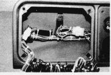
Left Hand Panel Components
Remove Panel
Remove screws (1) and carefully lift the panel out to the extent of the of the electrical harness.
Remove Warning Lights
All warning lights (23) can be removed in the same way. Disconnect the wires. Remove the nut from the light body on the back of the panel and withdraw the light assembly from the front.
Remove Lights Switch
Disconnect the wires from the switch (22). Remove screw (26) and pull off the knob (25). Remove nut (24) from the front of the panel, and withdraw the switch from the back.
Remove Switches
All switches (19) are removed in the same way. Disconnect the wires, remove the rubber cover and locknut from the front of the panel, and withdraw the switch from the back.
Remove
Circuit Breakers
All circuit breakers(2) are removed in the same way. Disconnect the wires. Remove the rubber cover and the nut from the front of the panel and withdraw the circuit breaker from the back.
Remove Flasher Unit
The flasher unit(20) is located behind the panel. Remove by carefully pulling it free from the socket.
Remove Brake Overstroke Warning Light Interuptor Unit
The interuptor unit(21) is located behind the panel. Remove by cutting the plastic ties securing the unit to the harness and disconnect the wires.
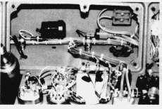
Center Panel Components
Remove Panel
Remove screws(6) and carefully lift the panel out to the extent of the electrical harness.
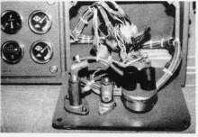
Remove Gages
All gauges(3) can be removed in the same way. Disconnect the wires from electric gages or the pipes from the mechanical gages. Remove the nuts(4) and brackets(5) which hold the gauge in place, and remove the gauge from the front of the panel.
Remove Low Air Pressure Warning Buzzer
The warning buzzer(18) is located behind the panel. Remove by separating snap connector(17) and remove the two mounting screws(16).
Remove Windscreen Washer Pump
The washer pump(14) is located behind the panel. Disconnect the pipes and wires and remove two bolts and nuts(15).
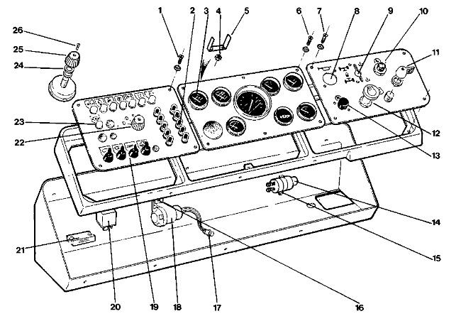
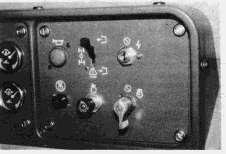
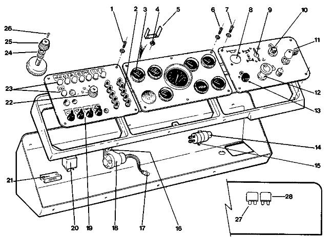
Dash Panel Arrangement (1) Screw (2) Circuit Breaker (3) Gauges (4) Nut (5) Bracket (6) Screw (7) Screw (8) Horn Valve (9) Differential Lock/Six Wheel Drive Air Valve (10) Isolator Switch (11) Start Switch (12) Ether Inject Switch (13) Engine Stop Switch (14) Windscreen Washer Pump (15) Bolt (16) Screw (17) Snap Connector (18) Low Air Pressure Warning Buzzer (19) Switches (20) Flasher Unit (21) Brake Overstroke Interuptor Unit (22) Lights Switch (23) Warning Lights (24) Nut (25) Knob (26) Screw