DOWNLOAD LINK
For some reason if link does not work download this pdf and then click
Product: TRACK-TYPE TRACTOR
Model: D4K2 XL TRACK-TYPE TRACTOR KM2
Configuration: D4K2 XL & D4K2 LGP Small Track Type Tractor KM200001-UP (MACHINE) POWERED BY C4.4 Engine
Operation and Maintenance Manual
Next Gen GRADE 3D for Certain Track-Type Tractors
Media Number -M0090205-04
Publication Date -01/07/2020
Design Surface Type
SMCS - 7220
The following types of designs are supported by the Cat GRADE system:
Date Updated -31/07/2020
DSZ job setup file (.dsz) - An ".dsz" file is a fast loading design surface. An ".dsz" file allows a machine to operate across large design surfaces. An ".dsz" file can be generated by Trimble Business Center v3.8 or later or can be translated from a ".svd" and ".cal" file using the Android application called FileFlipper. The ".dsz" file contains both design surface information and site calibration information.
Copyright 1993 - 2024 Caterpillar Inc. All Rights Reserved. Private Network For SIS Licensees. Tue Sep 10 23:16:23 UTC+0530 2024
i07282731
Product: TRACK-TYPE TRACTOR
Model: D4K2 XL TRACK-TYPE TRACTOR KM2
Configuration: D4K2 XL & D4K2 LGP Small Track Type Tractor KM200001-UP (MACHINE) POWERED BY C4.4 Engine
Operation and Maintenance Manual
Next Gen GRADE 3D for Certain Track-Type Tractors
Media Number -M0090205-04 Publication Date -01/07/2020 Date Updated -31/07/2020
Designs
SMCS - 7220
Introduction
Every job site has a defined construction surface that is based on the engineering design for the project. This engineering design is called the design surface.
In the Cat® GRADE with 3D system, the vertical and horizontal guidance information is provided by a design surface in a job setup file. The design may also contain a background line drawing.
Designs
A design must contain a design surface. The design surface contains vertical guidance information for a specific area. The design surface can be an irregular surface or a flat plane.
The difference in position between the height of the cutting edge and the height of the design surface, at the same place is called the cut or the fill. The software for the GRADE with 3D system displays the cut or the fill on the display and other important guidance information.
The GRADE with 3D system uses the design information to control the movement of the blade when the automatic controls are active.
Note: In some cases, the design surface is a large vertical distance from the current machine position. Use the working surfaces to raise or lower the design surface to a feasible working surface. For more information, refer to Section "Elevation Offset" of this manual.
Specifying a Design Surface
3D design surfaces are created in offboard software suites and loaded to the GRADE with 3D system.
3D Design Surfaces And Design Files
i07282730
A 3D design surface is defined by a digital design surface file. A design must contain a 3D design surface and can also contain background linework. The design surface contains vertical guidance information for a specific area. The design surface can be an irregular surface or a plane.
Design surfaces are created in the office and saved onto a USB flash drive in the form of a design file. From the USB flash drive, the design file can be loaded directly to the display. The GRADE with 3D system can contain more than one design file. However, the GRADE application will only load one design surface at a time for display and guidance.
Copyright 1993 - 2024 Caterpillar Inc. All Rights Reserved. Private Network For SIS Licensees. Tue Sep 10 23:16:13 UTC+0530 2024
Product: TRACK-TYPE TRACTOR
Model: D4K2 XL TRACK-TYPE TRACTOR KM2
Configuration: D4K2 XL & D4K2 LGP Small Track Type Tractor KM200001-UP (MACHINE) POWERED BY C4.4 Engine
Operation and Maintenance Manual
Next Gen GRADE 3D for Certain Track-Type Tractors
Media Number -M0090205-04
Publication Date -01/07/2020
Display Navigation
SMCS - 7220
Date Updated -31/07/2020
This section provides detailed information on the use of the views for guidance information and text information on the Cat® GRADE with 3D system.
Blade Focus
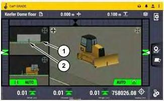
The position information that is shown on the display relates to the focus point of the cutting edge. Horizontal guidance is given to the blade tip that has focus. The red square on the cutting edge indicates which section of the blade has focus.
Note: Do not confuse the blade focus with the vertical guidance point.
Illustration 1
(1) Blade focus (right tip)
(2) Vertical guidance point (single point, center)
g06288467
Illustration 1 shows the cutting edge focus and vertical guidance points in the different views.
i07282682
Product: TRACK-TYPE TRACTOR
Model: D4K2 XL TRACK-TYPE TRACTOR KM2
Configuration: D4K2 XL & D4K2 LGP Small Track Type Tractor KM200001-UP (MACHINE) POWERED BY C4.4 Engine
Operation and Maintenance Manual
Next Gen GRADE 3D for Certain Track-Type Tractors
Media Number -M0090205-04 Publication Date -01/07/2020 Date Updated -31/07/2020
Horizontal Guidance
SMCS - 7220
Introduction
Horizontal guidance is provided to the operator via the center light bar and the text items that are on the display. A horizontal alignment must be selected before guidance can be shown. The operator can then use the light bar or the text items to steer the direction of the machine in relation to the design.
Horizontal guidance can be given to the following types of alignments:
• Design alignments in road files
• 3D lines alignment
• Master alignment of sloping surfaces
• Design boundary lines and linework in site maps and background plans
Note: The Cat® GRADE with 3D system gives guidance to any features in the road design file. Widening and superelevation are included.
Applying a horizontal offset to a selected alignment can help the operator construct the final surface.
Horizontal guidance is provided to the focus point on the blade.
Selecting an Alignment for Horizontal Guidance
In most cases, operator will probably use the horizontal offset icon on the works screen to reach the interface for selecting an alignment.
i07282709
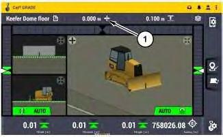
Illustration 1
g06289285 (1) Horizontal offset icon
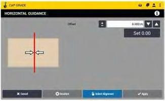
1. Touch and hold the "Horizontal Offset Icon" (1) to access the horizontal guidance screen.
Illustration 2
g06284626
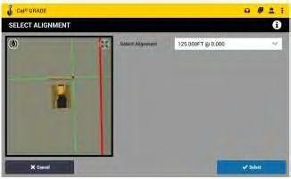
2. Press the "Select Alignment" button to choose an existing alignment in the loaded project.
Illustration 3
3. Touch the intended alignment on the plan view or select the alignment from the dropdown menu.
g06284627
4
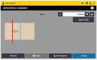
4. Adjust the offset if desired. The alignment line will be shown in the views as a blue line while any horizontal offset line will be shown as a red line. Horizontal guidance will be provided to the offset (red) line.
5
g06284629
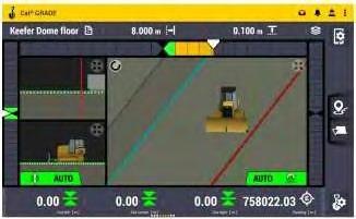
The center lightbar will provide horizontal guidance to the horizontal offset from the selected alignment.
Illustration 5 shows that there is an 8 m (26.2 ft) horizontal offset from the selected blue alignment line to the red offset line and the GRADE with 3D system is directing the operator to move the machine left to position the blade focus on the red offset line.
Illustration
g06284628
Illustration
6
As the blade position moves left and the blade focus intersects with the red offset line, the center lightbar shows that the blade focus is on the horizontal guidance line.
Copyright 1993 - 2024 Caterpillar Inc.
All Rights Reserved.
Private Network For SIS Licensees.
Tue Sep 10 23:16:03 UTC+0530 2024
Illustration
Product: TRACK-TYPE TRACTOR
Model: D4K2 XL TRACK-TYPE TRACTOR KM2
Configuration: D4K2 XL & D4K2 LGP Small Track Type Tractor KM200001-UP (MACHINE) POWERED BY C4.4 Engine
Operation and Maintenance Manual
Next Gen GRADE 3D for Certain Track-Type Tractors
Media Number -M0090205-04 Publication Date -01/07/2020 Date Updated -31/07/2020
Infield Designs
SMCS - 7220
3D Mode
Illustration 1
Infield designs
i07848415
The infield designs feature is used to create simple or complex design using the machine display.
The infield designs in the 3D mode function is a powerful tool that allows the operator to create and grade a surface using 3D designs. The 3D designs are created using machine blade tip focus point coordinates.
The infield 3D designs can be created "on-screen" or by utilizing a previous created template that has an alignment already predefined.
Note: For a new alignment, it is recommended to use the focus option.
The operator can create a multi-segment alignment with the focus point on the cutting edge of the blade, in addition to creating section. These alignment can then be applied to the section to create three-dimensional (3D) designs.
To create a 3D design, the following tasks must be completed in order:
• Define the starting point
• Define the horizontal alignment
• Correct the vertical alignment
• Create or select a section
• Apply the section to the alignment
• Modify or check the anchor point
• Check the design in 3D and edit if required
• Edit the Name of the design and save
Creating Infield Designs
To create infield designs, follow the below procedure:
Illustration 2
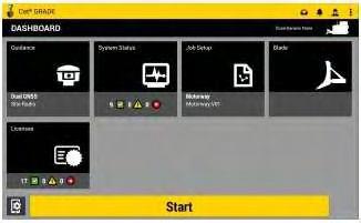
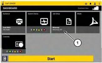
g06450500 Dashboard screen (1) "Job Setup" option
1. Press "Job Setup" option (1).
Illustration 3
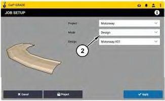
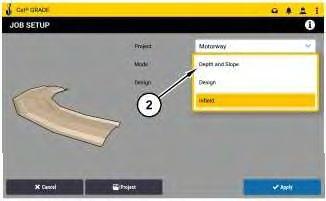
Job setup screen (2) "Mode" option
g06450999
Illustration 4
Job setup screen (2) "Mode" option drop-down
g06450507
2. Press "Mode" option (2) and select "Infield" from the drop-down menu.
Illustration 5
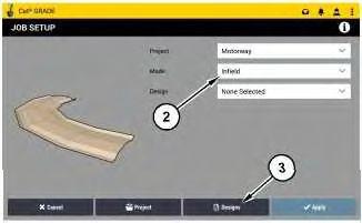
Job setup screen (2) "Mode" option (3) "Designs" option
3. Press "Designs" option (3).
g06450509
Illustration 6
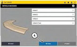
Infield designs screen (4) "Create" option
g06450510
4. Press "Create" option (4), to create a new infield design.
Illustration 7
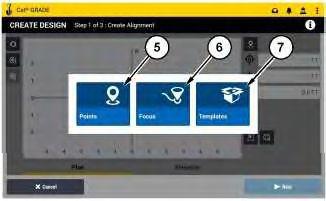
Create design screen (5) "Points" option (6) "Focus" option (7) "Templates" option
g06450513
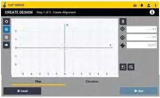
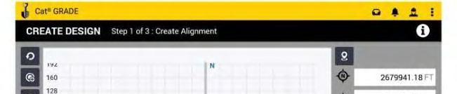
5. Once the "Create" option (4) is selected, the "Create Design" screen will appear.
6. The Infield "Create Design" has three selectable options, "Points" (5), "Focus" (6), and "Template" (7) to create or start an alignment.
Points (5) - The operator can build an alignment using the selected focus point on the cutting edge of the blade, by pressing "Focus" option (4).
Focus (6) - The operator can build an alignment using the selected focus point on the cutting edge of the blade, by pressing "Focus" option (6).
Template (7) - The operator can select an alignment from one of the template options that was previously created, predefined, and saved on the GRADE system, by pressing "Templates" option (7).
Illustration 8
Infield design - Points create screen
7. Select the desired menu.
Creating Alignment
Creating Alignment Work Tools
Illustration 9
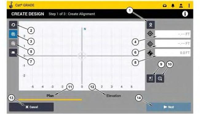
Create design screen
(1) Edit coordinate icon
(2) Undo icon
(3) Create a new point icon
(4) Northern coordinate field
(5) Delete a point icon
(6) Eastern coordinate field
(7) Focus point on the blade (right, center, and left)
g06450514
g06450518
(8) Elevation coordinate field
(9) Lock to grid option - active
(10) Zoom all option
(11) Plan view tab
(12) Elevation view tab
(13) Cancel
(14) Next
The Infield menu screen is equipped with many tools to aid the operator to create a design. Understanding these tools is critical to accomplish the desired infield designs. The following are the tool options available:
Illustration 10
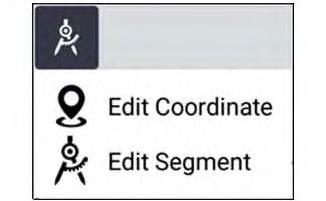
Edit coordinate and edit segment menu options
g06398573
Edit Coordinate (1) - Tap the desired menu icon to switch between Coordinates and Segments options. Coordinates option to can be used to edit the Northing, Easting, and Elevation (Height). Segment option can be used to edit the Distance, Angle, and Height.
Note: Tapping the edit icon will switch between Edit Coordinate and Edit Segment options.
Illustration 11
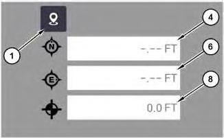
Edit coordinate menu option
(1) Edit coordinate icon
(4) Northern coordinate field
g06451495
(6) Eastern coordinate field
(8) Elevation coordinate field
Illustration 12 g06398570
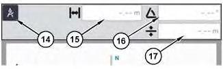
Edit segment menu option
(14) Edit segment icon
(15) Distance field
(16) Angle field
(17) Height field
Northern Coordinate field (4) - The operator can view the Northing coordinates and by pressing the field the operator can edit the Northing coordinates value to a desired value.
Eastern Coordinate field (6) - The operator can view the Eastern coordinates and by pressing the field the operator can edit the Eastern coordinates value to a desired value.
Elevation Coordinate field (8) - The operator can view the Elevation coordinates and by pressing the field the operator can edit the Elevation coordinates value to a desired value.
Undo icon (2) - The undo option allows the operator to undo the last edit that was done on Infield design screen.
Note: Redo function is not available on the infield screen.
Create a new point option (3)When the focus point used, this option is used to create a new point.
Note: The create a new point icon (3) appears in blue before the operator creates the first point in the field and the icon changes to black and white, once the point is created.
Delete a point option (5) - When the focus point used, this option is used to delete a point.
Focus point on the blade (Right, Center, or Left) (7) - By pressing the focus point option, the operator can select the focus point to be in the Right, Center, or Left of the blade cutting edge.
Lock to Grid - Active (9) - The Lock to grid is Active. This will lock all new points and touches to a grid. This will not apply to any new points created by the focus point or to the coordinates edits. The Lock to Grid option can be turned ON or OFF by tapping on the icon.
Lock to Grid - Inactive (9) - The Lock to grid is Inactive. This will unlock all new points and touches to a grid. The Lock to Grid option can be turned ON or OFF by tapping on the icon.
Zoom All option (10) - The Zoom option allows the operator to zoom out to the actual size on the display screen. Illustration 13
Plan View (11) - Plan view on the screen.
Elevation View (12) - Vertical (Elevation) Alignment option
Cancel option (13) - Cancel and go back to the previous menu.
Next option (14) - Accept and move to the next menu screen.
Edit Segment (14) - Tap the icon to switch between Coordinates and Segments menu option. Segment option can be used to edit the Distance, Angle from last segment, and Height.
Distance field (15) - The operator can view the actual Distance value and by pressing the field the operator can edit the distance value.
Angle field (16) - The operator can view the actual Angle from last segment value and by pressing the field the operator can edit the Angle from last segment value.
Height field (17) - The operator can view the actual Height value and by pressing the field the operator can edit the Height value.
Illustration 15 g06450522
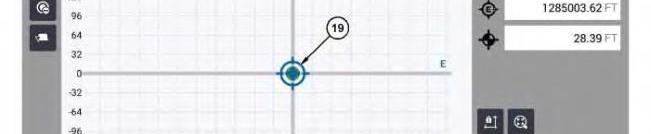
Infield design create screen - starting focus point (19) Starting focus point
Starting focus point (19) - The staring coordinates point on the plan view when it is used with the selected focus point.
Plain View and Elevation Icons
The drawing point icon - Drawing point with the coordinates.
The drawing point with focus point and coordinates - icon - Drawing point with the coordinates.
The drawing Point with focus point and the coordinates - This icon appears once the operator press and hold the drawing point or the point on the alignment.
Point on the alignment - This icon appears on the screen when the create a point option is pressed using the focus point, or when the point is moved to a new
position. If the point needs to be altered and moved to a new position, press and hold the point till the point turns yellow and becomes the drawing point with coordinates icon. Once the point becomes the drawing point with coordinates, the operator can move it to a different position on the screen.
Note: When the Drawing Point with Coordinates is dragged and moved to a new location, the point moves.
Note: Ensure that the new position to which the point is moved is an acceptable position and not an impossible position.
Note: Double tap a point to delete it.
Focus point on top of an alignment point - This icon indicates the focus point on the blade.
Drawing point with coordinates - This icon is an indication of the focus point on top of an alignment point (to start the drawing and create an alignment).
Point on the alignment - No icon will be shown on the screen.
Elevation View
Elevation Slope Alignment IconElevation Slope Alignment option is used to aligning the slopes of a Segments in the Elevation view to align or change the slope between the two blue highlights points on the screen. Refer to Illustration 33.
Note: When Elevation Slope Alignment option is pressed, the Vertical Alignments will be immediately applied.
Illustration 16 g06398613
Coordinates editing fields - The operator can edit the "Y" and "Z" Coordinates by taping the values in fields.
Illustration 17 g06398614
Slope distance and Angle from horizontal editing fields - The operator can edit the slope distance and the angle from horizontal by taping the values.
Illustration 18 g06398615
Scaling the entire sections with maintaining the "Y" and "Z" values (Distance and Height) - The operator can scale the entire section and maintain the "Y/Z" ration by tapping any of their fields and edit them to the desired value.
Illustration 19 g06398620
Scaling the entire sections without maintaining the "Y" and "Z" values - The operator can scale the section with a separate "Y/Z" ration by tapping any of their fields and edit them to the desired value.
Mirror
Illustration 20 g06398621
Mirror options
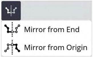
Mirror option - Tap the mirror icon to select Mirror from End or Mirror from Origin options.
Mirror from End option - The operator can use this option to replicate and reflect the section and attach it to the end.
Mirror from Origin option - The operator can use this option to replicate and reflect the section and attach it to the start.
Combine Alignments and Sections Options
Flip section and keeping the attachment point option - The operator can use this
option to flip the section and keeping the attachment point.
Move attachment point to the left option - The operator can use this option to move the Attachment point to the Left.
Move attachment point to the right option - The operator can use this option to move the Attachment point to the Right.
Section
On screen - On-screen option is used to touch the points that needs to be added.
Note: On-screen option is best for adding a section from a plan.
Focus - Focus option is used to create point using the focus point on the blade.
Note: Focus option is best for matching an existing feature.
Templates - Templates option is used to select an existing section.
Note: Templates option is best when there is a section already defined and available.
Defining the Start Point
The first point must be accurate, and it cannot be changed.
To create a point, follow the procedure below:
This is the sample of the manual click on the download link for complete manual