

For some reason if link does not work download this pdf and then click

Product: TRACK-TYPE TRACTOR
Model: D4D TRACK-TYPE TRACTOR 74U
Configuration: D4D TRACTOR / POWER SHIFT / 74U00480-UP (MACHINE) POWERED BY 3304 ENGINE
Disassembly and Assembly
D4 TRACTOR ENGINE
Media Number -REG00890-01
Publication Date -01/05/1974
SMCS - 1207-11; 1207-12
Date Updated -10/10/2001
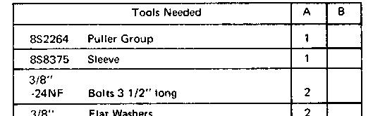

start by:
a) remove timing gear cover
b) remove fuel injection pump housing and governor
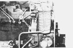
TYPICAL EXAMPLE
1. Remove all lines from the accessory drive housing (1) and fuel filter base.
2. Remove nut and washer from accessory drive shaft.
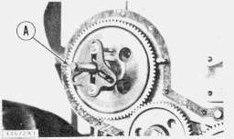
3. Remove the accessory drive gear with tooling (A). Remove sleeve from shaft.
Hold puller with hand to prevent injury when gear is removed from shaft.
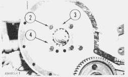
4. Remove bolts (2), locks (4) and retainer (3) that fasten the accessory drive housing to the plate.
5. Remove the accessory drive housing.
6. Remove fuel transfer pump.
7. Remove the accessory drive shaft from the housing.
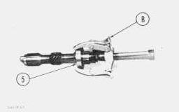
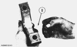
8. Remove bearing (5) from shaft with tool (B).

1. Heat the bearing for the accessory drive shaft in 300°F (149°C) oil and install the bearing on the shaft.
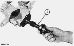
2. Install the accessory drive shaft (1) and bearing in the housing.
3. Install the fuel transfer pump.
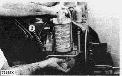
TYPICAL EXAMPLE
4. Install the accessory drive housing (2).
5. Install the retainer, locks and bolts.
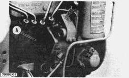
6. Turn the accessory drive shaft until tool (A) can be installed.
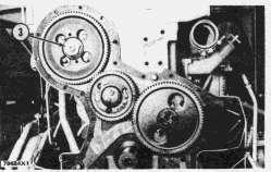
7. Install the sleeve, gear, washer and nut for the accessory drive shaft. Tighten nut (3) to 100 ± 10 lb. ft. (13.8 ± 1.4 mkg).
8. Connect the fuel lines.
Copyright 1993 - 2025 Caterpillar Inc. All Rights Reserved. Private Network For SIS Licensees.
Tue Apr 15 22:53:37 UTC+0700 2025
Product: TRACK-TYPE TRACTOR
Model: D4D TRACK-TYPE TRACTOR 74U
Configuration: D4D TRACTOR / POWER SHIFT / 74U00480-UP (MACHINE) POWERED BY 3304 ENGINE
Disassembly and Assembly
D4 TRACTOR ENGINE
Media Number -REG00890-01
SMCS - 1051-12; 1051-11
start by:
a) remove hood
Publication Date -01/05/1974
Date Updated -10/10/2001
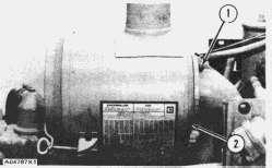
1. Remove six nuts (1) and washers from the air cleaner.
2. Remove air cleaner (2).
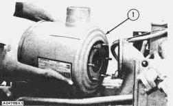
1. Put air cleaner (1) in position on the pipe.
2. Install the six washers and nuts that hold the air cleaner in position.
by: a) install hood
Copyright 1993 - 2025 Caterpillar Inc. All Rights Reserved. Private Network For SIS Licensees. Tue Apr 15 22:40:54 UTC+0700 2025
Product: TRACK-TYPE TRACTOR
Model: D4D TRACK-TYPE TRACTOR 74U
Configuration: D4D TRACTOR / POWER SHIFT / 74U00480-UP (MACHINE) POWERED BY 3304 ENGINE
Disassembly and Assembly
D4 TRACTOR ENGINE
Media Number -REG00890-01
SMCS - 1405-11; 1405-12
Remove Alternator
Publication Date -01/05/1974
Date Updated -10/10/2001
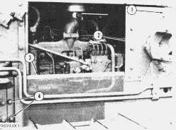
1. Remove four bolts (4) from panel (3). Remove two bolts (1) and washers from panel (2). Remove panel (2) and panel (3) (if so equipped).
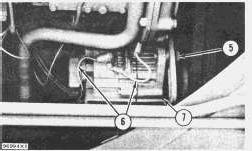
2. Remove wires (6) from the alternator. Put identification on the wires to prevent mixing at installation.
3. Loosen bolt (5). Remove the two bolts and washers that hold the alternator in position. Remove the belts from the pulley on the alternator. Remove alternator (7).
Install Alternator
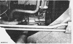
1. Put the alternator in position on the engine. Install the two bolts and washers that hold the alternator in position.
2. Connect the wires to the correct terminals on the alternator.
3. Put the belt on the pulley of the alternator. Make an adjustment to the belt tension. The movement of a used belt is 7/8 in. (22 mm) when a force of 25 lb. (11.3 kg) is made halfway between the pulleys. The movement of a new belt is 3/4 in. (19 mm) when the same force is made halfway between pulleys.
4. Install the two panels (if so equipped).
Copyright 1993 - 2025 Caterpillar Inc.
Rights Reserved.
Network For SIS Licensees.
Tue Apr 15 22:39:10 UTC+0700 2025
Product: TRACK-TYPE TRACTOR
Model: D4D TRACK-TYPE TRACTOR 74U
Configuration: D4D TRACTOR / POWER SHIFT / 74U00480-UP (MACHINE) POWERED BY 3304 ENGINE
Disassembly and Assembly
D4 TRACTOR ENGINE
Media Number -REG00890-01
Publication Date -01/05/1974
SMCS - 1224-11; 1224-12
Date Updated -10/10/2001

start by:
a) remove oil pan plate
b) remove balancer shafts
c) remove flywheel housing
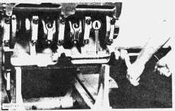
1. Remove the bearings for the balancer shaft with tool group (A). Remove the front bearing first.

1. Install the balancer shaft bearings in the cylinder block with tool group (A). Install the front bearing first. Make sure the oil holes in the bearings are in alignment with the oil holes in the cylinder block.
2. The front and rear bearings are to be .03 ± .02 in. (0.76 ± .051 mm) inside the ends of the block after installation. end by:
a) install balancer shafts
b) install flywheel housing
c) install oil pan plate
Copyright 1993 - 2025 Caterpillar Inc. All Rights Reserved. Private Network For SIS Licensees. Tue Apr 15 22:59:19 UTC+0700 2025
Product: TRACK-TYPE TRACTOR
Model: D4D TRACK-TYPE TRACTOR 74U
Configuration: D4D TRACTOR / POWER SHIFT / 74U00480-UP (MACHINE) POWERED BY 3304 ENGINE
Disassembly and Assembly
D4 TRACTOR ENGINE
Media Number -REG00890-01
SMCS - 1220-11; 1220-12
Publication Date -01/05/1974
Remove Balancer Shafts
start by:
a) remove timing gear cover
b) remove oil pump
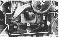
TYPICAL EXAMPLE
1. Remove bolts (1), locks and plates.
2. Remove balancers (2).
Date Updated -10/10/2001
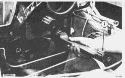
1. Put the balancer shaft (1) in position. Install the plates, locks and bolts.
NOTE: Balancer shafts must be correctly in time. See INSTALL OIL PUMP.
end by:
a) install oil pump
b) install timing gear cover
1993 - 2025 Caterpillar Inc.
Rights Reserved.
Network For SIS Licensees. Tue Apr 15 22:56:24 UTC+0700 2025
Product: TRACK-TYPE TRACTOR
Model: D4D TRACK-TYPE TRACTOR 74U
Configuration: D4D TRACTOR / POWER SHIFT / 74U00480-UP (MACHINE) POWERED BY 3304 ENGINE
Disassembly and Assembly
D4 TRACTOR ENGINE
Media Number -REG00890-01
SMCS - 1211-11; 1211-12
Publication Date -01/05/1974
Date Updated -10/10/2001

start by:
a) remove engine
b) remove flywheel housing
c) remove camshaft
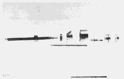
1. Remove the camshaft bearings starting with the front bearing with tool group (A).

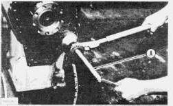
1. Install the camshaft bearings in the cylinder block starting with the front bearing. Install bearings with tool group (A). Install the bearings with the oil hole in alignment with the oil hole in the cylinder block.
2. The front and rear bearings after installation are to be .06 in. (1.5 mm) inside the ends of the cylinder block.
end by:
a) install camshaft
b) install flywheel housing
c) install engine
Product: TRACK-TYPE TRACTOR
Model: D4D TRACK-TYPE TRACTOR 74U
Configuration: D4D TRACTOR / POWER SHIFT / 74U00480-UP (MACHINE) POWERED BY 3304 ENGINE
Disassembly and Assembly
D4 TRACTOR ENGINE
Media Number -REG00890-01
SMCS - 1210-11; 1210-12
Remove Camshaft
start by:
a) remove valve lifters
b) remove timing gear cover
Publication Date -01/05/1974
Date Updated -10/10/2001
1. Turn the crankshaft until "C" mark on crankshaft gear (1) is in alignment with the "C" mark on camshaft gear (3).
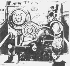
2. Put a mark on the teeth of the fuel injection pump drive gear at location (A). Put a mark on the idler gear and camshaft gear at location (B).
3. Remove camshaft bolts (2), locks and thrust washer.
4. Pull the camshaft out of the cylinder block.
5. Remove the bolts from the camshaft gear. Remove the gear from the camshaft.
1. Put the gear in position on the camshaft. Install the bolts and locks that hold the gear in position.
2. Put clean SAE 30 oil on the cams and bearing journals of the camshaft.
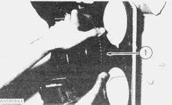
3. Put the camshaft and gear (1) in the correct position in the cylinder block.
NOTE: Make sure the timing marks are all in the correct positions.
4. Put the thrust washer in position and install the locks and bolts that hold the camshaft in position.
NOTE: If a replacement has been made for any of the timing gears, it will be necessary to put the shaft of the fuel pump in time with the engine. See REMOVE AND INSTALL FUEL INJECTION PUMP AND GOVERNOR AS A UNIT.
end by:
a) install timing gear cover
b) install valve lifters
Tue Apr 15 22:53:24 UTC+0700 2025
Product: TRACK-TYPE TRACTOR
Model: D4D TRACK-TYPE TRACTOR 74U
Configuration: D4D TRACTOR / POWER SHIFT / 74U00480-UP (MACHINE) POWERED BY 3304 ENGINE
Disassembly and Assembly
D4 TRACTOR ENGINE
Media Number -REG00890-01
Publication Date -01/05/1974
SMCS - 1219-10
Date Updated -10/10/2001

start by:
a) remove oil pump
b) remove oil pan plate
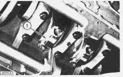
1. Turn the crankshaft until two pistons are at bottom center. Remove the connecting rod caps (1) from these connecting rods. Remove the lower half of bearings from the caps.
2. Push the connecting rods away from the crankshaft, and remove upper half of bearings.
3. At installation, clean the surfaces where the bearings fit, and install upper half of new bearings in the rods. Put clean SAE 30 oil on the bearings and crankshaft journals. Put the connecting rods in position on the crankshaft.
4. Clean the surfaces where the bearings fit and install lower half of new bearings in caps. Put clean SAE 30 oil on the bearings.
5. Put clean SAE 30 oil on the threads of all bolts.
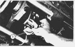
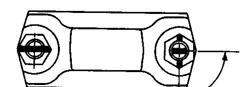

6. Check the bearing clearance with wire (A). Put the caps (1) in position on the connecting rods and install nuts on the bolts. Turn both nuts to a torque of 30 ± 3 lb.ft. (4.1 ± 0.4 mkg). Put a mark on the nut and on the end of each bolts, and turn both nuts 90° more.
7. Remove the rod cap, and measure thickness of wire. Rod bearing clearance with new bearings must be .0020 to .0076 in. (0.051 to 0.193 mm). Maximum permissible clearance with used bearings is .010 in. (0.25 mm).
8. Put the caps in position on the connecting rods and install nuts on the bolts. Turn both nuts to a torque of 30 ± 3 lb.ft. (4.1 ± 0.4 mkg). Put a mark on the nut and on the end of each bolt, and turn both nuts 90° more.
When installing connecting rod cap, be sure that the number on side of cap is near to and respective to the number on side of connecting rod.
9. Do Steps 1 through 8 again for other connecting rod bearings. end by:
a) install oil pan plate
Product: TRACK-TYPE TRACTOR
Model: D4D TRACK-TYPE TRACTOR 74U
Configuration: D4D TRACTOR / POWER SHIFT / 74U00480-UP (MACHINE) POWERED BY 3304 ENGINE
Disassembly and Assembly
D4 TRACTOR ENGINE
Media Number -REG00890-01
Publication Date -01/05/1974
Date Updated -10/10/2001
SMCS - 1160-11; 1160-12
Remove Crankshaft Front Seal

start by:
a) remove vibration damper and pulley
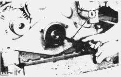
1. Remove the front seal with tool group (A).
Install Crankshaft Front Seal
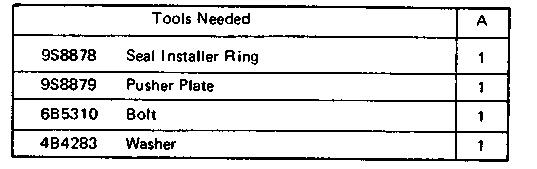
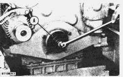
1. Install the crankshaft front seal with tooling (A) as follows.
2. Put clean engine oil on the lip of seal and on outside diameter of crankshaft.
3. Put 7F2770 Cement on the outside diameter of seal.
4. Put the seal in position on crankshaft with lip of seal toward the oil being sealed.
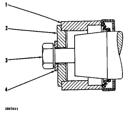
5. Put the seal installer ring (1) and pusher plate (2) in position on crankshaft.
6. Install the bolt (3) and washer (4).
7. Tighten bolt (3) until the pusher plate (2) makes contact with the front of the crankshaft.
8. Remove tooling (A).
end by:
a) install vibration damper and pulley
Product: TRACK-TYPE TRACTOR
Model: D4D TRACK-TYPE TRACTOR 74U
Configuration: D4D TRACTOR / POWER SHIFT / 74U00480-UP (MACHINE) POWERED BY 3304 ENGINE
Disassembly and Assembly
D4 TRACTOR ENGINE
Media Number -REG00890-01
Publication Date -01/05/1974
SMCS - 1203-10
Date Updated -10/10/2001
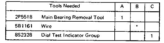
start by:
a) remove oil pan plate
b) remove oil pump
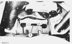
TYPICAL EXAMPLE
1. Remove the Nos. 1, 3, and 5 main bearing caps (1). Remove the crankshaft thrust bearings from No. 5 main. Remove lower halves of bearings from the caps.
2. Install tool (A) in the oil hole in the crankshaft journal and remove the upper halves of the main bearings by turning the crankshaft and moving the bearing out of the cylinder block with tool (A).
3. Put clean SAE 30 oil on the upper halves of the new main bearings. Install the upper halves on the main bearings with tool (A).
4. Put clean SAE 30 oil on the new crankshaft thrust bearings and install the bearings with the grooves in the bearings against crankshaft.
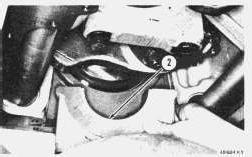
TYPICAL EXAMPLE
5. Clean the main bearing caps and install new lower bearing halves (2). Put clean SAE 30 oil on the bearings, bolt threads, and surfaces that contact the washers.
Make sure part number on cap is toward front of engine, and number on bottom of cap is the same as number on cap saddle when installing caps.
TYPICAL EXAMPLE
6. Check the bearing clearance with wire (B). Install the caps and tighten the bolts to a torque of 30 ± 3 lb.ft. (4.1 ± 0.4 mkg). Put a mark on each bolt head and the bearing caps. Tighten the bolts 90° more. Remove bearing caps and measure the thickness of the wire. The main bearing clearance (wire thickness) with new bearings must be .0030 to .0059 in. (0.076 to 0.150 mm). Maximum permissible clearance with used bearings is .010 in. (0.25 mm).
7. Put caps (1) in position on the engine and install the washers and bolts. Tighten the bolts to a torque of 30 ± 3 lb.ft. (4.1 ± 0.4 mkg). Put a mark on each bolt head and the bearing caps. Tighten the bolts 90° more.
8. Remove the Nos. 2 and 4 main bearing caps. Do Steps 2, 3, 5, 6, and 7 for the Nos. 2 and 4 mains.
For some reason if link does not work download this pdf and then click