Engine Design
SENR73810001
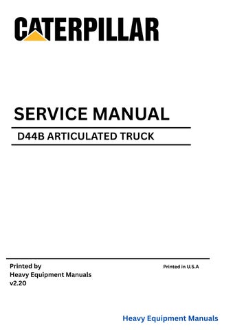
Number and Arrangement of Cylinders ... V-8
Firing Order (Injection Sequence) ... 1, 8, 4, 3, 6, 5, 7, 2
Rotation of Crankshaft (when seen from flywheel end) ... counterclockwise
Rotation of Fuel Pump Camshaft (when seen from pump drive end) ... counterclockwise
NOTE: Front end of engine is opposite to flywheel end. Left side and right side of engine are as seen from flywheel end. No. 1 cylinder is the front cylinder on the left side. No. 2 cylinder is the front cylinder of the right side.
Fuel System
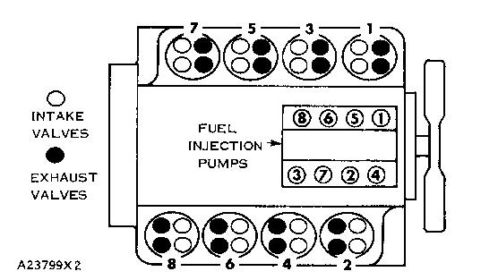
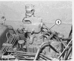
This engine has a pressure type fuel system. There is one injection pump and one injection valve for each cylinder. The injection pumps are in injection pump housing (4) on the top of the engine. The injection valves are in the precombustion chambers or adapters (for engines with direct injection) under the valve covers.
Fuel is pulled from fuel tank (6) through primary fuel filter (8) by fuel transfer pump (9). The transfer pump sends fuel through main fuel filter (11) to the manifold of the fuel injection pump housing.
Fuel in the manifold of the injection pump housing is the supply for the injection pumps. Some of the fuel in the manifold is constantly sent through an orifice in the tee or fitting that connects the return line to the manifold. The orifice controls the pressure in the manifold and the amount of fuel that returns to the tank. The constant flow of fuel back to the tank removes air from the system.
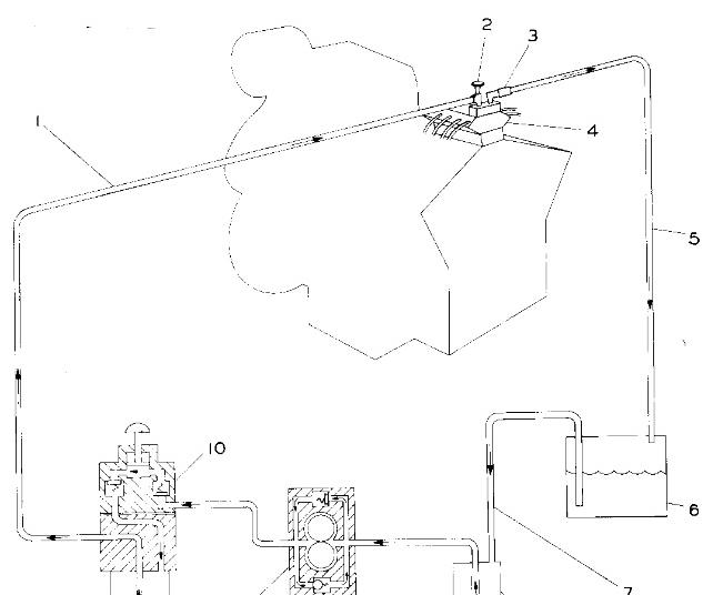
FUEL SYSTEM SCHEMATIC
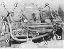
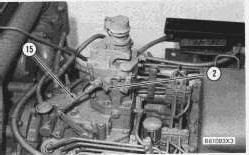
LOCATION OF FUEL SYSTEM COMPONENTS
1. Fuel inlet line for the injection pump housing. 2. Damper. 3. Adapter with orifice. 4. Injectionpump housing. 5. Fuel return line. 6. Fuel tank. 7. Fuel supply lines. 8. Primary fuel filter. 9. Fuel transfer pump. 10.Fuel priming pump. 11. Main fuel filter.
1. Fuel inlet line for the injection pump housing. 2. Damper. 3. Adapter with orifice. 4. Injectionpump housing. 5. Fuel
return line. 7. Fuel supply line. 9. Fuel transfer pump. 12. Nut for a fuel injection line at the injection pump. 13. Fuel manifold across the injection pump housing. 14. Adapter through the valve cover base. 15. Governor.
There is a surge damper (2) in the system to reduce shock loads on the fuel filter caused by high pressure from the injection pumps. On later engines, damper (2) is installed on the outlet side of fuel manifold (13). On earlier engines, damper (2) is installed on the inlet side of fuel manifold (13).
The injection pumps are in time with the engine. They send fuel to the injection valves under high pressure. When the fuel pressure at the injection valve is high enough the valve opens and sends fuel into the precombustion chamber or directly into the cylinder on direct injection engines.
Fuel transfer pump (9) has a bypass valve and a pressure relief valve. The bypass valve makes it possible for the priming pump to send fuel through the transfer pump. The pressure relief valve controls the maximum pressure of the fuel. When the pressure gets too high the valve opens and some of the fuel goes back to the inlet side of the pump.
When there is air on the inlet side of the fuel system use priming pump (10). Operation of the priming pump fills the system with fuel. This forces the air back into the tank.
Air can be removed from the fuel injection lines by loosening a fuel injection line nut (one at a time) at the valve cover base adapter. On PC Engines use the priming pump to remove the air. On DI Engines use the starter motor to turn the engine until fuel without air flows from the loosen nut. Tighten the nuts after air has been removed.
NOTE: Because of the check assemblies in the injection pump outlets for the DI engine, the priming pump will not give enough pressure to remove air from the fuel injection lines.
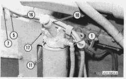
LOCATION OF FUEL SYSTEM COMPONENTS
1. Fuel inlet line to injection pump housing. 5. Fuel return line to tank. 7. Fuel supply line. 10.Fuel priming pump. 11. Main fuel filters. 16. Junction block. 17. Fuel outlet line from transfer pump and inlet line to main filters.
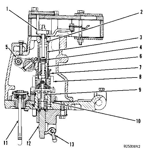
Fuel Injection Pump
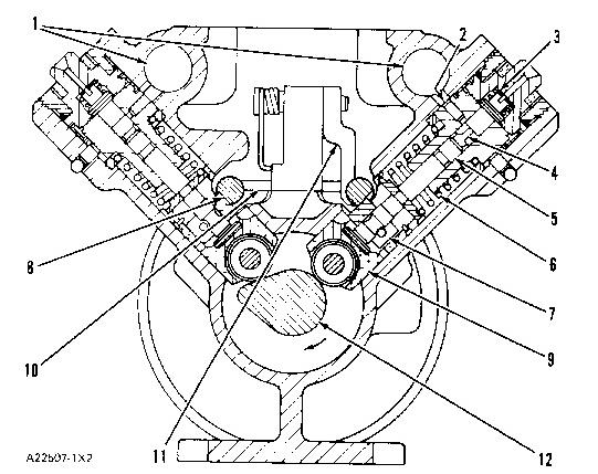
CROSS SECTION OF THE FUEL INJECTION PUMP HOUSING
1. Fuel manifold. 2. Inlet passage. 3. Check valve. 4. Pressure relief passage. 5. Pump plunger. 6.Spring. 7. Gear. 8. Fuel rack (left). 9. Lifter. 10. Link. 11. Lever. 12. Camshaft.
The rotation of the cams on the camshaft (12) cause lifters (9) and pump plungers (5) to move up and down. The stroke of each pump plunger is always the same. The force of springs (6) hold lifters (9) against the cams of the camshaft.
The pump housing is a "V" shape (similar to the engine cylinder block), with four pumps on each side.
When the pump plunger is down, fuel from fuel manifold (1) goes through inlet passage (2) and fills the chamber above pump plunger (5). As the plunger moves up it closes the inlet passage.
The pressure of the fuel in the chamber above the plunger increases until it is high enough to cause check valve (3) to open. Fuel under high pressure flows out of the check valve through the fuel line to the injection valve until the inlet passage opens into pressure relief passage (4) in the plunger. The pressure in the chamber decreases and check valve (3) closes.
The longer the inlet passage is closed the larger the amount of fuel which will be forced through check valve (3). The period for which the inlet passage is closed is controlled by the pressure relief passage. The design of the passage makes it possible to change the inlet passage closed time by rotation of the plunger. When the governor moves fuel racks (8) they move gears (7) that are fastened to plungers (5). This causes a rotation of the plungers.
The governor is connected to the left rack. The spring load on lever (11) removes the play between the racks and link (10). The fuel racks are connected by link (10). They move in opposite directions (when one rack moves in, the other rack moves out).
This is the sample of the manual if you need complete manual click on the Download button
Fuel Injection Valves (On Earlier Engines)
The fuel injection valves are installed in the precombustion chambers in engines equipped with precombustion chambers. An adapter takes the place of the precombustion chamber in engines equipped with direct injection. The precombustion chambers or adapters are installed in the cylinder heads.
Fuel, under high pressure from the injection pumps, is sent through the injection lines to the injection valves. The injection valves change the fuel to a fine spray for good combustion in the cylinders. The injection valves will not open until the fuel in the injection lines reaches a very high pressure. The valves then open quickly to release the fuel directly into the engine cylinder through orifices in the tip of each nozzle.
Fuel Injection Nozzles (On Later DI Engines)
The fuel injection nozzle is installed in an adapter in the cylinder head and is extended into the combustion chamber. The fuel injection pump sends fuel with high pressure to the fuel injection nozzle where the fuel is made into a fine spray for good combustion.
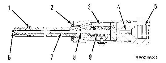
FUEL INJECTION NOZZLE
1. Carbon dam. 2. Seal. 3. Passage. 4. Filter screen. 5. Inlet passage. 6. Orifice. 7. Valve. 8. Diameter. 9. Spring.
Seal (2) goes against the nozzle adapter and prevents leakage of compression from the cylinder. Carbon dam (1) keeps carbon out of the bore in the nozzle adapter.
Fuel with high pressure from the fuel injection pump goes into inlet passage (5). Fuel then goes through filter screen (4) and into passage (3) to the area below diameter (8) of valve (7). When the pressure of the fuel that pushes against diameter (8) becomes greater than the force of spring (9), valve (7) lifts up. This occurs when the fuel pressure goes above the Valve Opening Pressure of the fuel injection nozzle. When valve (7) lifts, the tip of the valve comes off of the nozzle seat and the fuel will go through the six small orifices (6) into the combustion chamber.
The injection of fuel continues until the pressure of fuel against diameter (8) becomes less than the force of spring (9). With less pressure against diameter (8), spring (9) pushes valve (7) against the nozzle seat and stops the flow of fuel to the combustion chamber.
The fuel injection nozzle can not be disassembled and no adjustments can be made.
Hydra-Mechanical Governors
The governor controls the amount of fuel needed to keep a desired engine rpm over the complete engine speed range. The governor automatically makes up for variable engine loads to maintain a constant engine rpm.
The earlier and later governor operate the same. The earlier governors have two levers (13) and the later governors have a one piece lever (13). The shutoff solenoid and fuel ratio control have been moved from the injection pump housing to the governor housing on the later governors.
When the engine is operating, the balance between the centrifugal force of the governor weights and the force of the governor control on the governor spring, controls the movement of a valve and indirectly, the fuel rack. The valve directs pressure oil to either side of a rack positioning piston. Depending on the position of the valve, the rack is moved to increase and decrease the fuel to the engine to compensate for load variation.
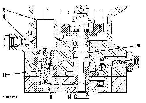
HYDRA-MECHANICAL GOVERNOR WITH DASHPOT
1. Collar. 2. Collar bolt. 3. Dashpot chamber. 4. Dashpot piston. 5. Lever assembly. 6. Dashpot spring. 7. Governor spring. 8. Governor weights. 9. Valve. 10. Cylinder. 11. Drive assembly. 12. Pin. 13. Lever.
The governor has governor weights (8) driven by the engine through the drive assembly (11). The governor has a governor spring (7), valve (9) and a piston. The valve and piston are connected to one fuel rack through pin (12) and lever (13).
The governor control, is connected to the governor control lever and controls only the compression of governor spring (7). Compression of the spring always pushes down to give more fuel to the
engine. The centrifugal force (rotation) of governor weights (8) always pulls up to get a reduction of fuel to the engine. When these two forces are in balance, the engine runs at the desired rpm (governed rpm).
The governor oil pump on top of the fuel injection pump housing sends engine oil under pressure to governor cylinder (10) through passage (18) around sleeve (19).
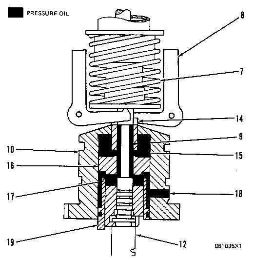
GOVERNOR IN INCREASED LOAD POSITION
7. Governor spring. 8. Governor weights. 9. Valve. 10. Cylinder. 12. Pin. 14. Oil drain passage for piston. 15. Upper oil passage in piston. 16. Piston. 17. Lower oil passage in piston. 18. Oil passage in cylinder. 19. Sleeve.
When the load on the engine increases, the engine rpm decreases and the rotation of governor weights (8) will get slower. The governor weights will move toward each other. Governor spring (7) moves valve (9) to open the oil passages in piston (16) and close oil drain passage (14). This lets the oil flow from passage (17), around valve (9), and through passage (15) to fill the chamber above piston (16). This pressure oil pushes piston (16) and pin (12) down to give more fuel to the engine. Engine rpm increases until the rotation of the governor weights is fast enough to be in balance with the force of the governor spring.
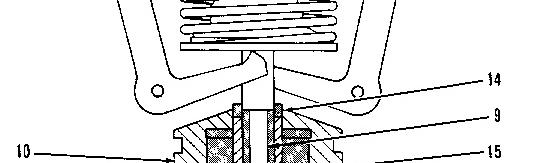
When there is a reduction in load on the engine, there will be an increase in engine rpm and the rotation of governor weights (8) will get faster. This will move valve (9) up. This stops oil flow from passage (17) and oil pressure above piston (16) goes out around valve (9) through the top of piston (16). Now, the pressure between sleeve (19) and piston (16) pushes the piston and pin (12) up. This causes a reduction in the amount of fuel to the engine. Engine rpm decreases until the centrifugal
force (rotation) of the governor weights is in balance with the force of the governor spring. When these two forces are in balance, the engine will run at the desired rpm (governed rpm).
GOVERNOR IN DECREASED LOAD POSITION
7. Governor spring. 8. Governor weights. 9. Valve. 10. Cylinder. 12. Pin. 14. Oil drain passage for piston. 15. Upper oil passage in piston. 16. Piston. 17. Lower oil passage in piston. 18. Oil passage in cylinder. 19. Sleeve.
When the engine rpm is at LOW IDLE, a spring loaded plunger in lever assembly (5) is in contact with a shoulder on the adjustment screw for low idle. To stop the engine, move the switch to the "OFF" position. This will cause the shutoff solenoid to move the spring loaded plunger over the shoulder on the low idle adjustment screw and move the fuel racks to the fuel shutoff position. With no fuel to the engine cylinders, the engine will stop. On later engines, to stop the engine manually, turn the shutoff lever on the governor housing to the shutoff position. On earlier engines, to stop the engine manually, pull back on the governor control.
Oil from the governor pump gives lubrication to the governor weight support (with gear), thrust bearing (under the governor spring), and drive gear bearing. The other parts of the governor get lubrication from "splash-lubrication" (oil thrown by other parts). Oil from the governor runs down into the housing for the fuel injection pumps.
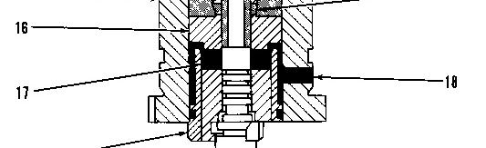
Some engines need a governor that has better control over the engine speed range than a standard hydra-mechanical governor gives. A piston (4) and spring (6) around bolt (2), plus an oil reservoir in the shutoff housing (adapter), and two adjustment screws (20 and 21) are added to the basic hydramechanical governor. These parts control the flow of oil into and out of dashpot chamber (3) above piston (4), through internal oil passages. With correct oil flow into and out of dashpot chamber (3),
the lower governor spring seat moves with more precision and the governor gives better control of the engine speed.
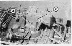
SIDE VIEW OF GOVERNOR
20. Adjustment screw for dashpot. 21. Adjustment screw for supply oil to reservoir.
The oil for the dashpot action comes from the engine lubrication system. Adjustment screw (21) controls the oil flow from the lubrication system into the reservoir, which has an overflow outlet back to the mechanical area of the governor. On earlier engines, adjustment screw (21) is located on top of the governor housing. Too much oil flow to the reservoir will fill the governor with oil and decrease engine performance. Too little oil flow does not give enough oil to reservoir. Now the governor will hunt (increase and decrease engine speed constantly) as air gets into dashpot chamber (3) and lets piston (4) and the lower governor spring seat move faster.
Dashpot adjustment screw (20) causes a restriction to oil flow into and out of dashpot chamber (3). Too much oil flow lets the lower governor spring seat move faster, and the governor will hunt. Too little oil flow will cause slow governor action.
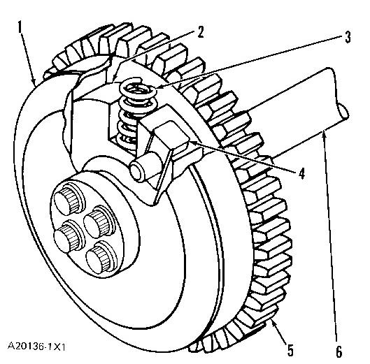
Automatic Timing Advance Unit
The automatic timing advance unit is installed on the front of the camshaft (6) for the fuel injection pump and is gear driven through the timing gears. The drive gear (5) for the fuel injection pump is connected to the camshaft (6) through a system of weights (2), springs (3), slides (4) and a flange (1). Each one of the two slides (4) is held on the gear (5) by a pin. The two weights (2) can move in guides inside the flange (1) and over the slides (4), but the notch for the slide in each weight is at an angle with the guides for the weight in the flange. As centrifugal force (rotation) moves the weights away from the center, against springs (3), the guides in the flange and the slides on the gear make the flange turn a little in relation to the gear. Since the flange is connected to the camshaft for the fuel injection pump, the fuel injection timing is also changed.
There is no adjustment for the timing advance unit.
AUTOMATIC TIMING ADVANCE UNIT
Fuel Ratio Control
1. Flange. 2. Weight. 3. Springs. 4. Slide. 5. Drive gear. 6. Camshaft.
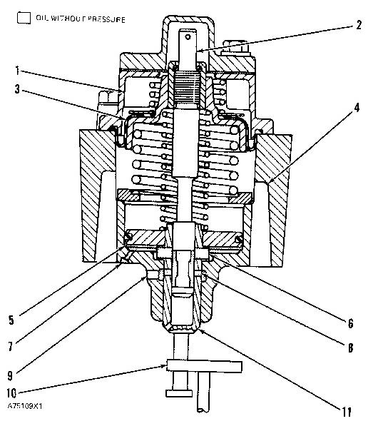
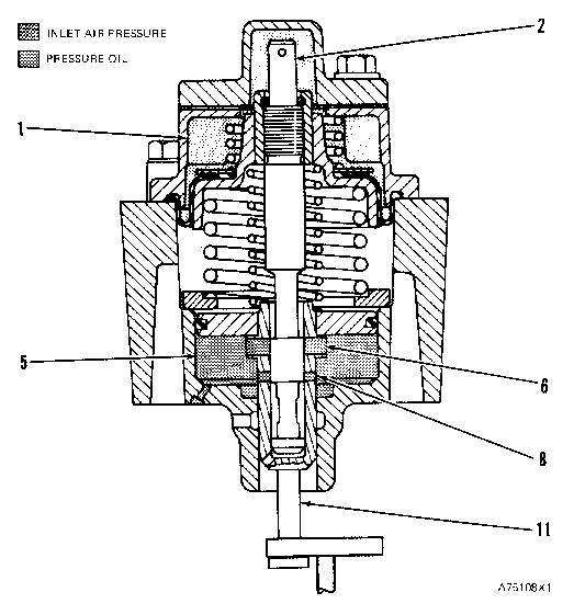
FUEL RATIO CONTROL (Engine Stopped)
1. Inlet air chamber. 2. Valve. 3. Diaphragm assembly. 4. Oil drains. 5. Pressure oil chamber. 6. Large oil passages. 7. Oil inlet. 8. Small oil passages. 9. Oil outlet. 10. Fuel rack linkage. 11. Valve.
With the engine stopped, valve (11) is in the fully extended position. The movement of fuel rack linkage (10) is not limited by valve (11).
When the engine is started oil flows through oil inlet (7) into pressure oil chamber (5). From chamber (5) the oil flows through large oil passages (6), inside valve (11), and out small oil passages (8) to oil outlet (9).
A hose assembly connects inlet air chamber (1) to the inlet air system. As the inlet air pressure increases it causes diaphragm assembly (3) to move down. Valve (2), that is part of the diaphragm assembly, closes large and small oil passages (6 and 8). When these passages are closed oil pressure increases in chamber (5). This increase in oil pressure moves valve (11) up. The control is now ready for operation.
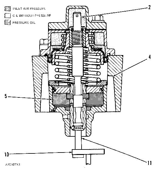
FUEL RATIO CONTROL (Ready for operation)
1. Inlet air chamber. 2. Valve. 5. Pressure oil chamber. 6. Large oil passages. 8. Small oil passages. 11. Valve.
When the governor control is moved to increase fuel to the engine, valve (11) limits the movement of fuel rack linkage (10) in the "Fuel On" direction. The oil in chamber (5) acts as a restriction to the movement of valve (11) until inlet air pressure increases.
As the inlet air pressure increases, valve (2) moves down and lets oil from chamber (5) drain through large oil passages (6) and out through oil drains (4). This lets valve (11) move down so fuel rack linkage (10) can move gradually to increase fuel to the engine. The control is designed not to let the fuel increase until the air pressure in the inlet manifold is high enough for complete combustion. It prevents large amounts of exhaust smoke caused by an air-fuel mixture with too much fuel.
The control movements take a very short time. No change in engine acceleration (rate at which speed increases) can be felt.
FUEL RATIO CONTROL (Increase in inlet air pressure)
Woodward PSG Governors
2. Valve. 4. Oil drains. 5. Pressure oil chamber. 10. Fuel rack linkage. 11. Valve.
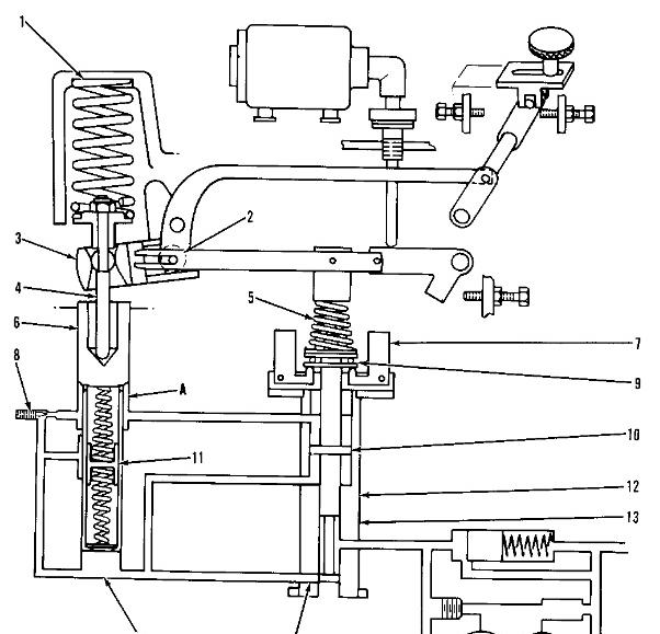
SCHEMATIC OF PSG GOVERNOR
1. Return spring. 2. Output shaft. 3. Output shaft lever. 4. Strut assembly. 5. Speeder spring. 6. Power piston. 7. Flyweights. 8. Needle valve. 9. Thrust bearing. 10. Pilot valve compensating land. 11. Buffer piston. 12. Pilot valve. 13. Pilot valve bushing. 14. Control ports. A. Chamber. B. Chamber.
Introduction
The Woodward PSG (Pressure compensated Simple Governor) can operate as an isochronous or a speed droop type governor. It uses engine lubrication oil, increased to a pressure of 1200 kPa (175 psi) by a gear type pump inside the governor, to give hydra/mechanical speed control.
Pilot Valve Operation
A gear on the rear of the fuel injection pump camshaft drives a vertical pinion shaft. The pinion shaft turns pilot valve bushing (13) counterclockwise, as seen from the drive unit end of the
governor. The pilot valve bushing is connected to a spring driven ballhead. Flyweights (7) are fastened to the ballhead by pivot pins. The centrifugal force caused by the rotation of the ballhead causes the flyweights to pivot out. This action of the flyweights changes the centrifugal force to axial force against speeder spring (5). There is a thrust bearing (9) between the toes of the flyweights and the seat for the speeder spring. Pilot valve (12) is fastened to the seat for the speeder spring Movement of the pilot valve is controlled by the action of the flyweights against the force of the speeder spring.
The engine is at the governed (desired) rpm when the axial force of the flyweights is the same as the force of compression in the speeder spring. The flyweights will be in the position shown. Control ports (14) will be closed by the pilot valve.
Fuel Increase
When the force of compression in the speeder spring increases (operator increases desired rpm) or the axial force of the flyweights decreases (load on the engine increases) the pilot valve will move in the direction of the drive unit. This opens control ports (14). Pressure oil flows through a passage in the base to chamber (B). The increased pressure in chamber (B) causes power piston (6) to move. The power piston pushes strut assembly (4), which is connected to output shaft lever (3). The action of the output shaft lever causes clockwise rotation of output shaft (2). This moves the fuel control linkage (15) in the FUEL ON direction.
PSG GOVERNOR INSTALLED
2. Output shaft. 15. Fuel control linkage.
As the power piston moves in the direction of return spring (1) the volume of chamber (A) increases. The pressure in chamber (A) decreases. This pulls the oil from the chamber inside the power piston, above buffer piston (11) into chamber (A). As the oil moves out from above buffer piston (11) to fill chamber (A), the buffer piston moves up in the bore of the power piston. Chambers (A and B) are connected respectively to the chambers above and below the pilot valve compensating land (10). The pressure difference felt by the pilot valve compensating land adds to the axial force of the flyweights to move the pilot valve up and close the control ports. When the flow of pressure oil to chamber (B) stops, so does the movement of the fuel control linkage.
Fuel Decrease
When the force of compression in the speeder spring decreases (operator decreases desired rpm) or the axial force of the flyweights increases (load on the engine decreases) the pilot valve will move in the direction of speeder spring (5). This opens control ports (14). Oil from chamber (B) and pressure oil from the pump will dump through the end of the pilot valve bushing. The decreased pressure in chamber (B) will let the power piston move in the direction of the drive unit. Return spring (1) pushes against strut assembly (4). This moves output shaft lever (3). The action of the output shaft lever causes counterclockwise rotation of output shaft (2). This moves fuel control linkage (15) in the FUEL OFF direction.
EARLIER PSG GOVERNOR
6. Power piston. 8. Needle valve. 10. Pilot valve compensating land. 11. Buffer piston. 14. Control ports. A. Chamber. B. Chamber.
As power piston (6) moves in the direction of the drive unit the volume of chamber (A) decreases. This pushes the oil in chamber (A) into the chamber above buffer piston (11). As the oil from chamber (A) flows into the power piston, it moves the buffer piston down in the bore of the power piston. The pressure at chamber (A) is more than the pressure at chamber (B). Chambers (A and B) are connected respectively to chambers above and below the pilot valve compensating land (10). The pressure difference felt by the pilot valve compensating lands adds to the force of the speeder spring to move the pilot valve down and close the control ports. When the flow of oil from chamber (B) stops, so does the movement of the fuel control linkage.
Hunting
There is a moment between the time the fuel control linkage stops its movement and the time the engine actually stops its increases or decrease of rpm. During this moment there is a change in two forces on the pilot valve, the pressure difference at the pilot valve compensating land and the axial force of the flyweights.
The axial force of the flyweights changes until the engine stops its increase or decrease of rpm. The pressure difference at the pilot valve compensating land changes until the buffer piston returns to its original position. A needle valve (8) in a passage between chambers (A and B) controls the rate at which the pressure difference changes. The pressure difference makes compensation for the change in the axial force of the flyweights until the engine stops its increase or decrease of rpm. If the force on the pilot valve compensating land plus the axial force of the flyweights is not the same as the force of the speeder spring, the pilot valve will move. This movement is known as hunting (movement of the pilot valve that is not the result of a change in load or desired rpm of the engine).
The governor will hunt each time the engine actually stops its increase or decrease of rpm at any other rpm than that desired. The governor will hunt more after a rapid or large change of load or desired rpm than after a gradual or small change.
PSG GOVERNOR INSTALLED (Typical Example)
8. Needle valve.
Speed Adjustment
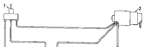
Speed adjustments are made by a 24V DC reversible synchronizing motor (2). The motor is controlled by a switch (1) that can be put in a remote location.
3 WIRE SYNCHRONIZING MOTOR SHOWN
1. Switch. 2. Motor.
The synchronizing motor drives clutch assembly (3). The clutch assembly protects the motor if it is run against the adjustment stops.
When the clutch assembly is turned clockwise it pushes link assembly (4) down. The force of compression in speeder spring (5) is increased. This causes pilot valve (6) to move down; see PILOT VALVE OPERATION. The engine will increase speed, then get stability at a new desired rpm.
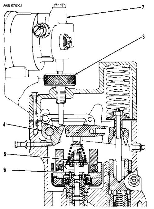
PSG GOVERNOR
2. Synchronizing motor. 3. Clutch assembly. 4. Link assembly. 5. Speeder spring. 6. Pilot valve.
When the clutch assembly is turned counterclockwise the link assembly moves up. The force of compression in the speeder spring is decreased. This causes the pilot valve to move up. The engine will decrease speed, then get stability at a new desired rpm.
NOTE: The clutch assembly can be turned manually if necessary.
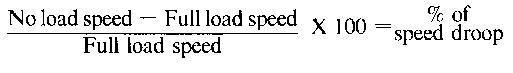
Speed Droop
Speed droop is the difference between no load rpm and full load rpm. This difference in rpm divided by the full load rpm and multiplied by 100 is the percent of speed droop.
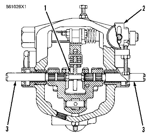
PSG GOVERNOR
1. Pivot pin. 2. Bracket for droop adjustment screw. 3. Output shafts.
The speed droop of the PSG governor can be adjusted. The governor is isochronous when it is adjusted so that the no load and full load rpm is the same. Speed droop permits load division between two or more engines that drive generators connected in parallel or generators connected to a single shaft.
Speed droop adjustment on PSG governors is made by movement of pivot pin (1). When the pivot pin is put in alignment with the output shafts, movement of the output shaft lever will not change the force of the speeder spring. When the force of the speeder spring is kept constant, the desired rpm will be kept constant. See PILOT VALVE OPERATION. When the pivot pin is moved out of alignment with the output shafts, movement of the output shaft lever will change the force of the speeder spring proportional to the load on the engine. When the force of the speeder spring is changed, the desired rpm of the engine will change.
An adjustment lever outside the governor connected to pivot pin (1) by link (4) is used to make an adjustment of the speed droop.
This is the sample of the manual if you need complete manual click on the Download button