

Previous Screen
Product: ARTICULATED TRUCK
Model: D400D ARTICULATED TRUCK 8TF
Configuration: D40D, D400D ARTICULATED TRUCK 8TF00001-UP (MACHINE) POWERED BY 3406 ENGINE
Disassembly and Assembly
Mechanical Suspension With Fixed Damper - Disassemble
SMCS - 7324-015-ME
Disassembly Procedure
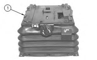
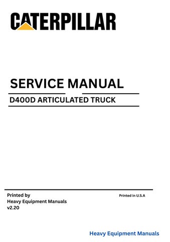
Illustration 1
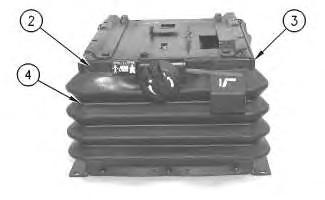
Illustration 2
2. Remove fasteners (2). Remove two retainers (3) and boot (4) .
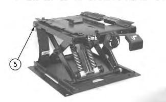
Illustration 3
g00288293
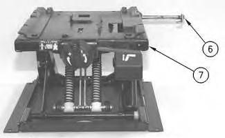
Illustration 4
g00288294
3. Remove locknut (5). Remove upper shaft assembly (6) from upper housing (7) .
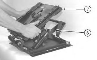
Illustration 5
g00288295
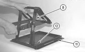
4. Tip upper housing (7) forward and slide the upper housing off scissor assembly (8) .
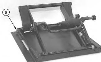
Illustration 6
g00288336
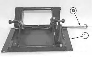
Illustration 7
g00288337
5. Remove locknut (9) from lower shaft assembly (10). Remove lower shaft assembly (10) from lower housing (11) .
8
6. Remove scissor assembly (8) from lower housing (11). Lift the scissor assembly and slide the scissor assembly out of slider track (12) .
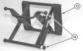
Illustration 9
g00288340
7. Remove four rollers (14) and two tether belts (13) .
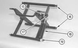
Illustration 10
8. Remove four bearings (16). Remove retainer (17), two bearings (15) and (19), and damper (18) .
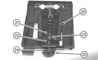
Illustration 11
g00288344
9. Remove pin (21) from the end of weight adjustment screw (22). Turn weight adjustment knob (25) in the negative (-) direction in order to relieve the tension on springs (20). Remove pin (24), weight adjustment knob (25), the thrust bearing, two races, weight adjustment screw (22) and nut (23) .
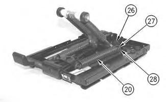
Illustration 12
g00288345
10. Remove retaining ring (27) from each side of height adjustment shaft (28). Remove two springs (20) and plastic bearings (26) from height adjustment shaft (28) .
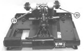
Illustration 13
g00288346
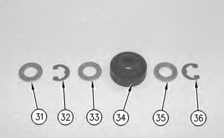
Illustration 14
g00288348
11. Remove roller assembly (30) from each side of suspension arm (29). Remove retaining rings (32) and (36), washers (31), (33) and (35), and rollers (34) .
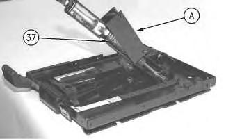
Illustration 15
g00288349
16
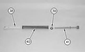
12. Attach Tool (A) to spring assembly (37), as shown. Use Tool (A) to remove the spring assembly from the shaft as a unit.
13. Use Tool (A) to slowly release the compression on spring assembly (37). Disassemble spring assembly (37). Remove guide bushing (38), spring (40), retainer (39) and rod assembly (41) .
14. Repeat Steps 12 and 13 for the spring assembly on the other side of the suspension arm.
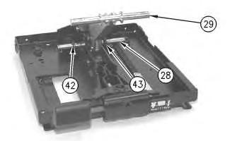
Illustration 17
15. Remove spacers (42) and (43) from shaft (28). Remove the shaft and suspension arm (29) .
18
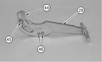
16. Remove retaining rings (45) and (46). Use a hammer and a punch to remove the pins. Remove cam (44) from suspension arm (29) .
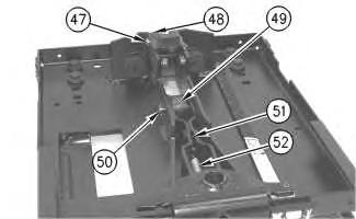
Illustration 19
g00288354
17. Remove retaining ring (50). Use a hammer and a punch to remove the pin. Remove roller (49). Remove retaining ring (47). Use a hammer and a punch to remove the pin. Remove roller (48) and two spacers. Remove spring (52) and arm assembly (51) .
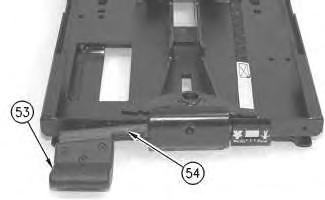
Illustration 20
18. Remove the key for the height adjustment lever. (The key is not shown.) Remove handle (53) and height adjustment lever (54) .
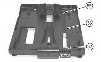
Illustration 21
g00288356
19. Remove pin (57) from the bracket. Cut tie-wraps (55). Remove indicator band (56) .
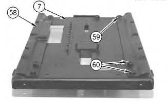
Illustration 22
g00288357
20. Remove four bolts (60), two bolts (59), the washers, and the locknuts from two brackets (58). Remove two brackets (58) from upper housing (7) . Copyright 1993 - 2025 Caterpillar Inc.