Product:INDUSTRIALENGINE
Model:D398INDUSTRIALENGINE66B
Configuration:D398BENGINE66B03561-UP
OperationandMaintenanceManual D379,D398,D399LOCOMOTIVEENGINES
MediaNumber-SEBU5528-00PublicationDate-01/10/1977DateUpdated-11/10/2001
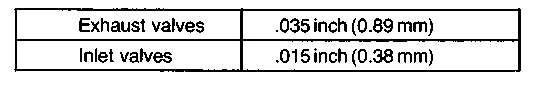
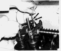
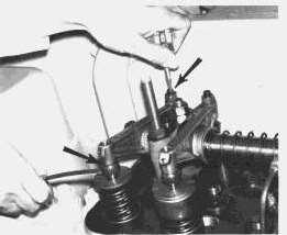
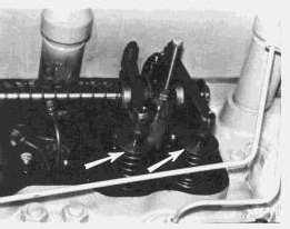
AdjustingValveLash(EngineStopped)Counterclockwise RotationViewedfromFlywheel
Copyright1993-2024CaterpillarInc. AllRightsReserved. PrivateNetworkForSISLicensees.
ThuAug2216:35:19UTC+05302024
Product:INDUSTRIALENGINE
Model:D398INDUSTRIALENGINE66B
Configuration:D398BENGINE66B03561-UP
OperationandMaintenanceManual D379,D398,D399LOCOMOTIVEENGINES
MediaNumber-SEBU5528-00PublicationDate-01/10/1977DateUpdated-11/10/2001 AirCleanerAndValveMaintenance
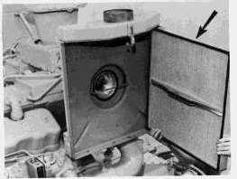
AirCleanerServiceIndicator
Beforestarting,checkthewindowoftheindicator.Iftheredpistonislockedintheraisedposition, servicetheaircleanerasoutlined.
NOTE:Havespareelementsonhandtoinstallwhilecleaningusedelements.
NOTICE
ServicetheaircleanerwiththeengineSTOPPED.
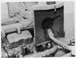
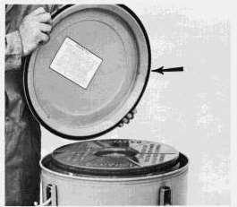
1.Removetheaircleanercoverandelement.
This is the sample of the manual if you need complete manual Click Here to download
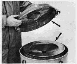
2.Covertheturbochargerairinletopeningtopreventdirtfromenteringtheengine.
3.Cleantheinsideoftheaircleanercoverandtheaircleanerbody.
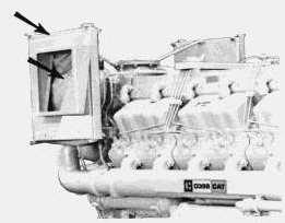
AIRINLETCOVER
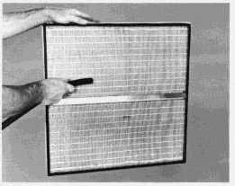
4.Inspectthereplacementelementfordamageanddirt.
5.Removethecoveringfromtheturbochargerinletopening.
6.Installtheelement.
NOTICE
Thereinforcingbraceacrossthemiddleofpanel-typeelementsfits overthesupportingbaroftheturbocharger.
7.Installtheaircleanercover.
8.Resettheserviceindicatorpistonbypushingtheresetbutton.(Seetheinstructionsforaircleaner elementcleaning).
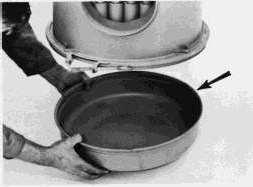
EmptyingDustCollectorCup
1.Loosentheclampingboltonthelowerbody.
2.Removeandemptythedustcollectorcup.
3.Inspectandinstalltheseal;installanewsealifnecessary.
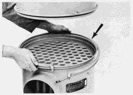
4.Inspectthetubesinthelowerbody.Ifdirty,cleanthetubeswitharoundbottlebrush.
5.Installthedustcollectorcup.
TwoStageAirCleaner
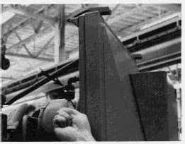
CleaningtheLowerBody
1.Removethedustcollectorcup.
2.Loosentheclampingboltontheupperbody.
3.Removethelowerbody.Cleanthetubesfrombothends.
4.Inspectandinstalltheupperbodyseal.Installanewsealifitisdamaged.
InstallingReplacementFilterElement
1.Removethecover.
2.Removetheinnercoverandfilterelement.Incoldweather,astuckinnercovermayberemoved bywarmingtheaircleanercoverto70-75°F(21-24°C).
3.Cleanallpartsoftheaircleaner.
4.Inspectthereplacementelementfordamageandcleanliness.
5.Installtheelement,innercover,andwingnut.Tightenthewingnuttopreventdustfrom bypassingthefilterelement.
6.Installthecover.
If,afterservicingtheaircleaner,theexhaustsmokeand/orlossofpowercontinues;ortheservice indicatorlocksintheraisedposition,discardthatelementandinstallanewelement.Installanew elementatleastonceayear.
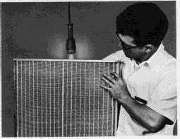
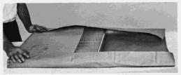
CleaningUsedAirCleanerElements
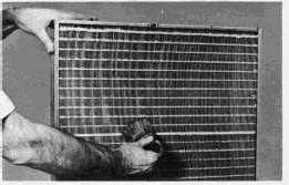
CleaningWithPressureAir
1.Useclean,dryair-30PSI,maximum.Holdthenozzleatleastoneinchfromtheelementata slightangle.(Adirectblastcanripthepleating.)
2.DirecttheairstreamalongthecompletelengthofeachpleatontheCLEANESTsideofthe element.(Thiswillloosenthedirtfromthedirtierside.)
3.BlowthelooseneddirtfromtheDIRTYside.
4.DirecttheairfromtheCLEANsidethroughtotheDIRTYsidetoremovedirtblownintothe pleating.
CleaningWithWater
1.Usecleanwateratnomorethan40PSI.Donotuseanozzle.
2.DirectthewaterstreamalongthecompletelengthofeachpleatontheCLEANsideofthe element.
3.DirectwateralongthecompletelengthofeachpleatontheDIRTYsideoftheelement.
4.RinsetheCLEANsideoftheelement.
5.Allowthecleanedelementtodrythoroughly.
CleaningWithDetergent
1.Washbothsidesoftheelementinasolutionofwarmwaterandnon-sudsinghouseholddetergent.
2.RinsetheCLEANESTsideoftheelementwithcleanwater(40PSImaximum)alongthe completelengthofeachpleat.
3.Rinsetheoppositesideoftheelementalongthecompletelengthofeachpleat.
4.Rinsethefirstsideagaintoremovealllooseneddirt.
5.Allowthecleanedelementtodrythoroughly.
StoringCleanedElements
1.Holdthedriedelementinfrontofalightedelectricbulb.Carefullyinspecttheelementfortiny, pinpointsoflight.Anylightshowingindicatesapleathasrupturedandwilltearwithfurtheruse. Discardtheelement.
2.Wrapusableelementsinheavypaper.
3.Storethewrappedelementinadry,cleanplace.
1.Stoptheengineandallowittocoolatleast20minutes.
2.Removetheflywheelhousingtimingcover.
3.Bartheflywheelinthedirectionofnormalrotation.Alignthe"TC1"timingmarkwiththe flywheelhousingtimingpointer.
4.Wipethebaseofthevalvecoverstokeepdirtfromgettingintothevalvemechanism.
5.Removebothvalvecovers.
6.ObservetherockersforcylinderNo.1.DetermineifthepistonisonCOMPRESSIONor EXHAUSTstroke.
CompressionStroke:Bothinletandexhaustvalverockerscanbemovedfreely.
ExhaustStroke:Onlyinletvalverockermovesfreely.
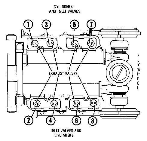
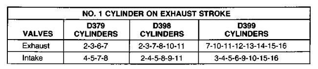
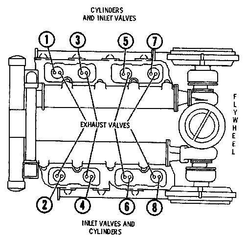
NUMBERINGOFCYLINDERS
D379ENGINESHOWN(D398ANDD399ENGINESVALVESANDCYLINDERSARESIMILARLY IDENTIFIED)
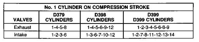
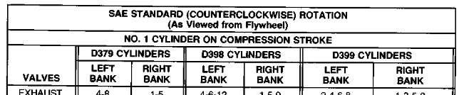
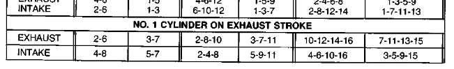
7.Usingthechartthatapplies:"NO.1CYLINDERONCOMPRESSIONSTROKE"or"NO.1 CYLINDERONEXHAUSTSTROKE",setthosevalveslistedunderthecolumns"LEFTBANK" and"RIGHTBANK"foryourengine.
8.Bartheflywheelinthedirectionofnormalflywheelrotation.AligntheTDCtimingmarkwith thepointerontheflywheelhousing.
9.Setthosevalvesspecifiedundertheremainingheading:"NO.1CYLINDERONEXHAUST STROKE"or"NO.1CYLINDERONCOMPRESSIONSTROKE".
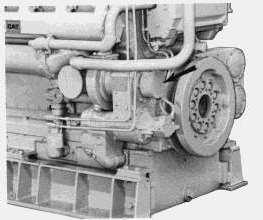
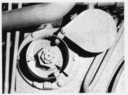
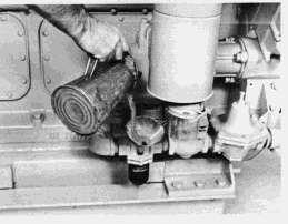
AirStartingMotorLubrication
AirStartingMotorOiler
Themotoroilerlubricatesthevanesofthestartingmotorwithafineoilmistasthemotoris operating.
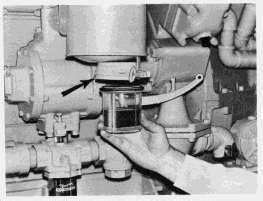
EmptyingCollectorJar
Thecollectorjarcollectsboththeoilafterithaslubricatedthestartingmotorvanes,andthe moisturecondensationfromthecompressedair.Emptythecollectorjarwheneverthejarbecomes halffull.
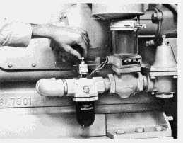
FillingOilerJar
Whentheoilerjarbecomeshalfempty,removetheoilfillerplugandfillthejarwithcleanoil. RefertoLUBRICATIONANDMAINTENANCECHARTforproperoil.
NOTICE
Neverallowthejartobecomeempty.Thestartingmotorwillbe damagedbylackofproperlubrication.
AdjustingtheAirStartingMotorOilerFeed
Ifnecessary,adjusttheoilertoreleaseapproximatelyfourdropsofoilperminuteintothestarting motorairsystem.
1.MovethecompressionreleaselevertotheSTARTposition,andmovethegovernorcontrol levertotheSHUTOFFposition.
2.Pullupontheairstartcontrolleverandcranktheengine.
3.Countthedropsofoilreleasedperminuteintotheairstream.
a.Turnthevalveneedle(theuppermostknobontheoiler)counterclockwisetoincreasethe numberofdrops.
b.Turnthevalveneedleclockwisetodecreasethenumberofdrops.
ThuAug2216:38:05UTC+05302024
Product:INDUSTRIALENGINE
Model:D398INDUSTRIALENGINE66B
Configuration:D398BENGINE66B03561-UP
OperationandMaintenanceManual D379,D398,D399LOCOMOTIVEENGINES
MediaNumber-SEBU5528-00PublicationDate-01/10/1977DateUpdated-11/10/2001
Attachments
GaugesAndIndicators
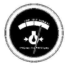
OilPressureGauge
Oilpressureisnormallygreaterafterstarting.Astheoilwarms,oilpressuredecreases.Asengine speeddecreases,oilpressuredecreases.Atlowidle,hotoilshouldregisternearthemiddlerange ofthegaugescale.Stoptheengineanddeterminethecauseifthereisnooilpressure,orifthe indicatorfluctuates.
Ifthegaugereadingfluctuatesaftertheloadisstable:
1.Removetheload.
2.Reduceenginespeedtolowidle.
3.Observetheoillevel.MaintaintheoillevelbetweentheADDandFULLmarkonthedipstick. Ifthereadingcontinuestofluctuatewhentheoilleveliscorrect,stopengineandcallyour Caterpillardealer.
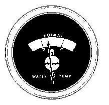
EngineJacketWaterTemperatureGauge
Operatingtemperatureismaintainedbywatertemperatureregulatorsandradiatorshutters.High coolanttemperaturesresultswhenthecoolingsystemdoesnotdissipateengineheatproperly.If overheatingoccurs,havethecoolingsystemandradiatorsinspected.
Iftheoperatingtemperatureisbelowtheopeningtemperatureofthewatertemperatureregulators, havetheregulatorschecked.
TheengineshouldoperatewithintheNORMAL(green)range.Iftheengineisoperatinginthe (red)rangeandsteambecomesapparent:
1.ReducetheloadandengineRPM.
2.Inspectforcoolantleaks.
3.Determineiftheenginemustbeshutdownimmediately;oriftheenginecanbesafelycooled byreducingtheload.
SeeCOOLINGSYSTEMMAINTENANCEINSTRUCTIONS.
NOTICE
Donotaddcoldwatertoahotengine:Crackingofenginecomponents mayoccur.Allowtheenginetocool,thenaddcoolant.
Ifthetemperaturegaugereadingcontinuouslyregistersinornearthecoldrange(white)while operatingunderload,havethefollowingchecksmade:
1.Havethewatertemperaturegaugecheckedforaccuracy.
2.Havethetemperatureregulatorsremovedandcheckedforpropertemperaturerange.Replace regulatorsifnecessary.
SeeCOOLINGSYSTEMMAINTENANCEINSTRUCTIONS.
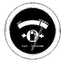
FuelPressureGauge
Thefuelpressuregaugeindicatespressureofthefuelpumpedtotheengineinjectionpumps.As thefilterscollectdirt,thefuelpressuredropsuntilthegaugeregistersintheOUTrangeand engineperformancedecreases.Whenthisoccurs,cleantheprimaryfuelfilter.Iflowfuelpressure isstillindicated,replacethefuelfilterelements.
SeetheFUELSYSTEMMAINTENANCEINSTRUCTIONS.
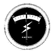
Ammeter
Theammetershouldregisterinthechargingrangewhentheengineisrunningabovelowidle.If thegaugeregistersadischargewithanincreaseinenginespeed,shutofftheengineanddetermine thecause.
AirCleanerServiceIndicator
Whenthegaugeindicatorlocksintheredrange,servicetheaircleaner.Withtheenginestopped; seeAIRINDUCTIONANDEXHAUSTSYSTEMMAINTENANCEINSTRUCTIONS.
Shuttheenginedownifworkonoraroundtheengineisrequired.
SafetyAlarmsAndShutoffDevices
ElectricSafetyAlarmOperation
Whenafaultconditionoccurs-eitherhighwatertemperatureorlowoilpressure-amicroswitchin thesensingunitisactuatedandcompletesacircuittoeitheralight,abellorahorn.Thelightor soundwarnstheoperatortheenginemustbestoppedtopreventdamagetotheengine.
Thehighwatertemperaturealarmswitchislocatedintheregulatorhousing.Thesensormustbe incontactwiththecoolantinordertooperate.Alowcoolantlevelwillnotactuatetheswitch.
Theoilpressurealarmisenergizedwhentheoilpressurefallsbelowthesafeoperatinglimits.For thisreason,itmaybedesirabletoturnthealarmtotheOFFpositionwhenstoppingtheengine. ThealarmmustbeturnedtotheOFFpositionbeforestartinginordertoallowtheenginetostart. TheknobwillmovebyitselftotheRUNpositionafternormaloilpressureisreached.
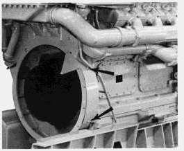
MechanicalSafetyShutoff
Themechanicalsafetyshutoffdeviceismechanicallydrivenandshutsoffthefuelwheneitheran overspeedoralowoilpressureconditionexists.Theshutoffmountsintheveeoftheenginetothe rearofthegovernor.
Toprotecttheengineagainstoperatingwithinsufficientoilpressure,ageardrivenslideisheld fromtheenginedrivenwormshaftbynormaloilpressure.Ifoilpressuredropsbelowsafelimits, theslideengagestherevolvingwormshaftandispropelledagainstalatchingmechanism.The latchdisengages,aspring-loadedrodstrikesagainstthefuelrackandmovesthefuelracktothe fueloffposition.Theenginewillstop.
Ifsufficientoilpressuredoesnotdevelopafterstarting,theenginewillrunapproximately7 secondsatoperatingspeedandthenwillshutdown.Therefore,checktheoilpressuregauge readingimmediatelyafterstarting.
MECHANICALSHUTOFFCROSSSECTION
1.Slide
2.OverspeedCarrier
3.WormShaft
4.Latch
5.Spring-loadedRod
Toprotecttheengineagainstoverspeeding,aspring-loadedweight,rotatedbyanenginegear train,isforcedoutwardbycentrifugalforce.Theweightstrikesthelatchmechanismdiscussed above.Thelatchdisengages,thespring-loadedrodstrikesagainsttherackandmovesittothefuel offposition.Theenginewillstop.
Bypressingtheemergencystopbutton,theoverspeedweightisreleased,theweightstrikesthe latchmechanism,andthespring-loadedrodstrikestherack,andmovesittothefueloffposition; stoppingtheengine.
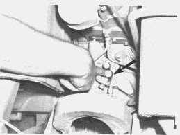
SafetyShutoffResetControls
Aftereithermechanicalshutoffdevicehasstoppedtheengine,theshutoffcontrolsmustbereset beforethefuelrackcanbemovedfromtheshutoffpositionandtheenginestarted.First,push downontheresetbutton,thenpushtheresetleveruntilthesafetymechanismlatches.
PUSHINGRESETLEVER
Iftheresetleverdoesnotreturntoitsoriginalpositionafterlatchingthesafetymechanism,check thecableforkinksorotherinternalresistance.Thecablemustmovefreely.
NOTICE
DONOTuseanyemergencyshutoffcontrolfornormalshutdown. Theemergencyshutoffcontrolsareforemergenciesonly.
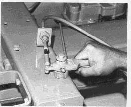
SafetyShutoffTesting
Shutoffdevicesoperateonlywhenanabnormalconditionexists,therefore,itisimpossibleto knowiftheyareinworkingconditionduringnormaloperation.Sinceitisimportantthattheywill operatewhennecessary,havetheshutoffdevicescheckedevery6monthsbyyourCaterpillar dealerorauthorizedpersonnel.
PUSHINGRESETBUTTON
Donotusetheseshutoffdevicesfornormalenginestopping.Suchusemaycausefailureofthese parts.
DeterminingCauseForAShutdown
Anytimetheengineisshutdownbythesafetycircuit,thecausemustbedeterminedand correctivemeasuresmustbetakenbeforestartingtheengine.
HighWaterTemperature
1.Determineifthelocomotiveisoverloadedinrelationtotonnagebeingpulled.Highaltitudeor hotairenteringtheradiatorcancreateanover-heatedengineconditionforanotherwisenormal load.
2.Checktheradiatorfandrive.
3.Checkthewaterlevel.Lowwaterlevelwillnotshuttheenginedown,butmaycontributeto otherfailures.
4.Checkshutteroperation.Dirtorobjectsmaypreventtheshuttersfromproperlyopening.
5.Checktheobjectsobstructingairflowthroughtheradiator.
6.Checkforfaultywaterpumpoperation,collapsedhoses,failedshuttemperatureregulators,or dirtycoolingsystem.
LowOilPressure
1.Checktheoillevel.Withtheenginestopped,theoillevelmustbebetweentheADDandFULL mark.Ifoillevelislow,determinethecause.
2.Checkfornew,wetoilaccumulationsatallgasketedjoints.Checkforleaks.
3.Ifvisualcheckscannotdeterminethecause,cranktheenginewithfueloff.Ifhardcrankingor unusualnoisesareheard,immediatelystopcranking.Haveinternalchecksmadeontheengine.
4.Checkforexcessivesmokeintheexhaustgasses.
5.Checkforexcessiveblow-by.
Copyright1993-2024CaterpillarInc. AllRightsReserved. PrivateNetworkForSISLicensees.
ThuAug2216:33:35UTC+05302024
This is the sample of the manual if you need complete manual Click Here to download