Product: INDUSTRIAL ENGINE
Model: D398 INDUSTRIAL ENGINE 66B
Configuration: D398B ENGINE 66B03561-UP
Operation and Maintenance Manual D379, D398, D399 LOCOMOTIVE ENGINES
-01/10/1977
-11/10/2001
Adjusting Valve Lash (Engine Stopped)Counterclockwise Rotation Viewed from Flywheel
Copyright 1993 - 2024 Caterpillar Inc.
Rights Reserved.
Network For SIS Licensees. Thu Aug 22 16:35:19 UTC+0530 2024
Product: INDUSTRIAL ENGINE
Model: D398 INDUSTRIAL ENGINE 66B
Configuration: D398B ENGINE 66B03561-UP
Operation and Maintenance Manual
D379, D398, D399 LOCOMOTIVE ENGINES
Media Number -SEBU5528-00 Publication Date -01/10/1977 Date Updated -11/10/2001
Air Cleaner And Valve Maintenance
Air Cleaner Service Indicator
Before starting, check the window of the indicator. If the red piston is locked in the raised position, service the air cleaner as outlined.
NOTE: Have spare elements on hand to install while cleaning used elements.
NOTICE
Service the air cleaner with the engine STOPPED.
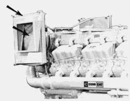
Single Stage Air Cleaner
1. Remove the air cleaner cover and element.
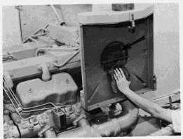
2. Cover the turbocharger air inlet opening to prevent dirt from entering the engine.
3. Clean the inside of the air cleaner cover and the air cleaner body.
AIR INLET COVER
4. Inspect the replacement element for damage and dirt.
5. Remove the covering from the turbocharger inlet opening.
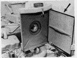
6. Install the element.
NOTICE
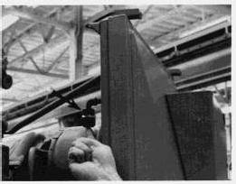
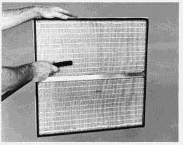
The reinforcing brace across the middle of panel-type elements fits over the supporting bar of the turbocharger.
This is the sample of the manual click on the download link for complete manual
DOWNLOAD LINK
For some reason if link does not work download this pdf and then click
7. Install the air cleaner cover.
8. Reset the service indicator piston by pushing the reset button. (See the instructions for air cleaner element cleaning).
Two Stage Air Cleaner
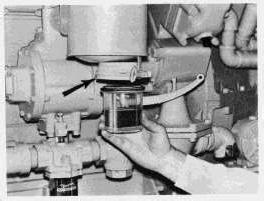
Emptying Dust Collector Cup
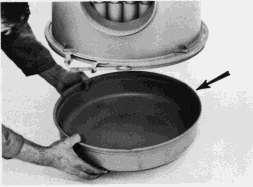
1. Loosen the clamping bolt on the lower body.
2. Remove and empty the dust collector cup.
3. Inspect and install the seal; install a new seal if necessary.
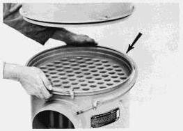
4. Inspect the tubes in the lower body. If dirty, clean the tubes with a round bottle brush.
5. Install the dust collector cup.
Cleaning the Lower Body
1. Remove the dust collector cup.
2. Loosen the clamping bolt on the upper body.
3. Remove the lower body. Clean the tubes from both ends.
4. Inspect and install the upper body seal. Install a new seal if it is damaged.
Installing Replacement Filter Element
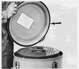
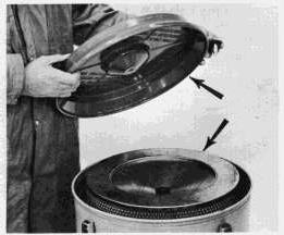
1. Remove the cover.
2. Remove the inner cover and filter element. In cold weather, a stuck inner cover may be removed by warming the air cleaner cover to 70 - 75°F (21 - 24°C).
3. Clean all parts of the air cleaner.
4. Inspect the replacement element for damage and cleanliness.
5. Install the element, inner cover, and wing nut. Tighten the wing nut to prevent dust from bypassing the filter element.
6. Install the cover.
If, after servicing the air cleaner, the exhaust smoke and/or loss of power continues; or the service indicator locks in the raised position, discard that element and install a new element. Install a new element at least once a year.
Cleaning Used Air Cleaner Elements
Cleaning With Pressure Air
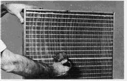
1. Use clean, dry air-30 PSI, maximum. Hold the nozzle at least one inch from the element at a slight angle. (A direct blast can rip the pleating.)
2. Direct the air stream along the complete length of each pleat on the CLEANEST side of the element. (This will loosen the dirt from the dirtier side.)
3. Blow the loosened dirt from the DIRTY side.
4. Direct the air from the CLEAN side through to the DIRTY side to remove dirt blown into the pleating.
Cleaning With Water
1. Use clean water at no more than 40 PSI. Do not use a nozzle.
2. Direct the water stream along the complete length of each pleat on the CLEAN side of the element.
3. Direct water along the complete length of each pleat on the DIRTY side of the element.
4. Rinse the CLEAN side of the element.
5. Allow the cleaned element to dry thoroughly.
Cleaning With Detergent
1. Wash both sides of the element in a solution of warm water and non-sudsing household detergent.
2. Rinse the CLEANEST side of the element with clean water (40 PSI maximum) along the complete length of each pleat.
3. Rinse the opposite side of the element along the complete length of each pleat.
4. Rinse the first side again to remove all loosened dirt.
5. Allow the cleaned element to dry thoroughly.
Storing Cleaned Elements
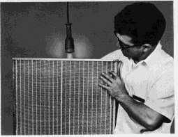
1. Hold the dried element in front of a lighted electric bulb. Carefully inspect the element for tiny, pin points of light. Any light showing indicates a pleat has ruptured and will tear with further use Discard the element.
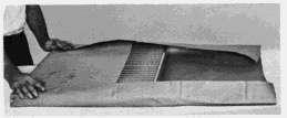
2. Wrap usable elements in heavy paper.
3. Store the wrapped element in a dry, clean place.
Engine Valve Lash Adjustment
Preparing To Set Valve Lash
1. Stop the engine and allow it to cool at least 20 minutes.
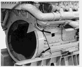
2. Remove the flywheel housing timing cover.
3. Bar the flywheel in the direction of normal rotation. Align the "TC1" timing mark with the flywheel housing timing pointer.
4. Wipe the base of the valve covers to keep dirt from getting into the valve mechanism.
5. Remove both valve covers.
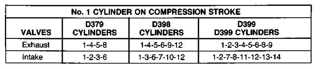
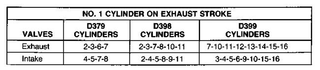
6. Observe the rockers for cylinder No. 1. Determine if the piston is on COMPRESSION or EXHAUST stroke.
Compression Stroke: Both inlet and exhaust valve rockers can be moved freely.
Exhaust Stroke: Only inlet valve rocker moves freely.
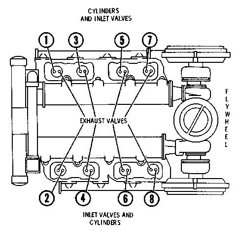
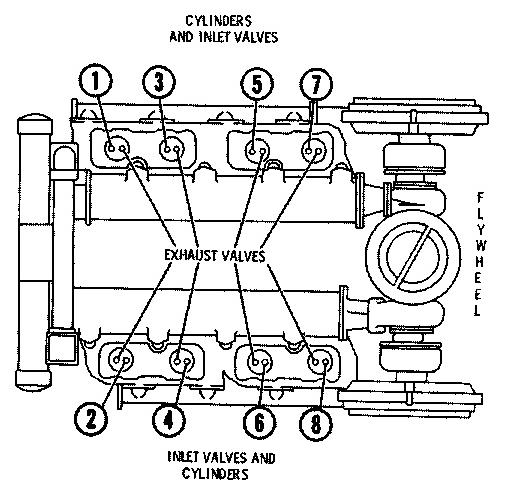
NUMBERING OF CYLINDERS
D379 ENGINE SHOWN (D398 AND D399 ENGINES VALVES AND CYLINDERS ARE SIMILARLY IDENTIFIED)
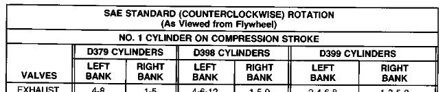
7. Using the chart that applies: "NO. 1 CYLINDER ON COMPRESSION STROKE" or "NO. 1 CYLINDER ON EXHAUST STROKE", set those valves listed under the columns "LEFT BANK" and "RIGHT BANK" for your engine.
8. Bar the flywheel in the direction of normal flywheel rotation. Align the TDC timing mark with the pointer on the flywheel housing.
9. Set those valves specified under the remaining heading: "NO. 1 CYLINDER ON EXHAUST STROKE" or "NO. 1 CYLINDER ON COMPRESSION STROKE".
Adjusting Valve Lash
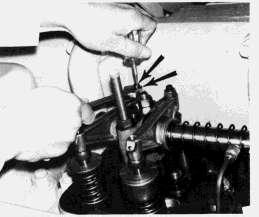
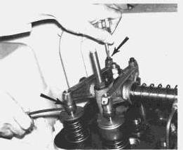
1. Loosen the locknut on the adjusting screw.
2. Hold the locknut and turn the adjusting screw to obtain the proper lash.
3. Hold the adjusting screw and tighten the locknut.
4. Recheck the lash.
Checking Valve Rotators
After checking all valve clearances, and before installing the valve covers:
1. Start the engine.
2. Move the governor control to low idle position.
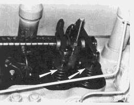
3. Watch the serrations on each valve retainer. Each valve retainer should turn slightly each time the valve closes.
If a valve retainer fails to rotate, contact your Caterpillar dealer. Repairs must be made to prevent burning the valve.
If all valves rotate, proceed as follows:
4. Stop the engine.
5. Inspect and install valve cover gaskets. Install new gaskets if necessary.
6. Install the valve covers.
7. Install the flywheel housing timing cover. Copyright 1993 - 2024 Caterpillar Inc. All Rights Reserved.
Network For SIS Licensees. Thu Aug 22 16:36:26 UTC+0530 2024
Product: INDUSTRIAL ENGINE
Model: D398 INDUSTRIAL ENGINE 66B
Configuration: D398B ENGINE 66B03561-UP
Operation and Maintenance Manual D379, D398, D399 LOCOMOTIVE ENGINES
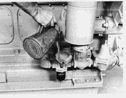
Air Starting Motor Lubrication
Air Starting Motor Oiler
The motor oiler lubricates the vanes of the starting motor with a fine oil mist as the motor is operating.
Emptying Collector Jar
The collector jar collects both the oil after it has lubricated the starting motor vanes, and the moisture condensation from the compressed air. Empty the collector jar whenever the jar becomes half full.
Filling Oiler Jar
When the oiler jar becomes half empty, remove the oil filler plug and fill the jar with clean oil. Refer to LUBRICATION AND MAINTENANCE CHART for proper oil.
NOTICE
Never allow the jar to become empty. The starting motor will be damaged by lack of proper lubrication.
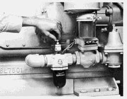
Adjusting the Air Starting Motor Oiler Feed
If necessary, adjust the oiler to release approximately four drops of oil per minute into the starting motor air system.
1. Move the compression release lever to the START position, and move the governor control lever to the SHUTOFF position.
2. Pull up on the air start control lever and crank the engine.
3. Count the drops of oil released per minute into the air stream.
a. Turn the valve needle (the uppermost knob on the oiler) counterclockwise to increase the number of drops.
b. Turn the valve needle clockwise to decrease the number of drops.
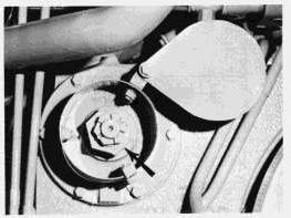
ADJUSTING MOTOR OILER Thu Aug 22 16:38:05 UTC+0530 2024
Product: INDUSTRIAL ENGINE
Model: D398 INDUSTRIAL ENGINE 66B
Configuration: D398B ENGINE 66B03561-UP
Operation and Maintenance Manual D379, D398, D399 LOCOMOTIVE ENGINES
Attachments
Gauges And Indicators
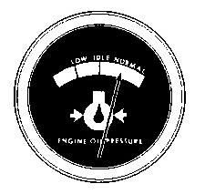
Oil Pressure Gauge
Oil pressure is normally greater after starting. As the oil warms, oil pressure decreases. As engine speed decreases, oil pressure decreases. At low idle, hot oil should register near the middle range of the gauge scale. Stop the engine and determine the cause if there is no oil pressure, or if the indicator fluctuates.
If the gauge reading fluctuates after the load is stable:
1. Remove the load.
2. Reduce engine speed to low idle.
3. Observe the oil level. Maintain the oil level between the ADD and FULL mark on the dipstick. If the reading continues to fluctuate when the oil level is correct, stop engine and call your Caterpillar dealer.
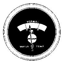
Engine Jacket Water Temperature Gauge
Operating temperature is maintained by water temperature regulators and radiator shutters. High coolant temperatures results when the cooling system does not dissipate engine heat properly. If overheating occurs, have the cooling system and radiators inspected.
If the operating temperature is below the opening temperature of the water temperature regulators, have the regulators checked.
The engine should operate within the NORMAL (green) range. If the engine is operating in the (red) range and steam becomes apparent:
1. Reduce the load and engine RPM.
2. Inspect for coolant leaks.
3. Determine if the engine must be shut down immediately; or if the engine can be safely cooled by reducing the load.
See COOLING SYSTEM MAINTENANCE INSTRUCTIONS.
NOTICE
Do not add cold water to a hot engine: Cracking of engine components may occur. Allow the engine to cool, then add coolant.
If the temperature gauge reading continuously registers in or near the cold range (white) while operating under load, have the following checks made:
1. Have the water temperature gauge checked for accuracy.
2. Have the temperature regulators removed and checked for proper temperature range. Replace regulators if necessary.
See COOLING SYSTEM MAINTENANCE INSTRUCTIONS.
Fuel Pressure Gauge
The fuel pressure gauge indicates pressure of the fuel pumped to the engine injection pumps. As the filters collect dirt, the fuel pressure drops until the gauge registers in the OUT range and engine performance decreases. When this occurs, clean the primary fuel filter. If low fuel pressure is still indicated, replace the fuel filter elements.
This is the sample of the manual click on the download link for complete manual