Previous Screen
Product: ARTICULATED TRUCK
Model: D35HP ARTICULATED TRUCK 3FD
Configuration:
Disassembly and Assembly
Dash Panel Components - D250B and D300B
Dash Panel Components - D250B and D300B
NOTICE
Moving dash panels may cause electrical connections to ground on the panel housing. Disconnect the batteries before working on the dash panels.
Compressed air will be released when air pipes are disconnected from the dash panels.
This can cause personal injury. Loosen connections slowly and wear protective clothing and glasses.
Before removing any electrical cables, clearly mark the cable and the connection to aid correct assembly.
Left Hand Panel Components.
Remove Panel
Remove the five screws(21) securing the panel trim(20), and lift the trim off the panel housing. Remove screws(16) and lift the panel out to the extent of the electrical harness.
Remove Ether Inject Switch and Engine Stop Switch.
Remove both switches as follows. Disconnect the wires. Loosen the switch locknut on the back of the panel, unscrew and remove the pushbutton cover on the front of the panel, and withdraw the switches(13) and (15) from the back.
Remove Isolator Switch
Disconnect the wires. Remove the nut from the front of the panel and withdraw the switch(14) from the back.
Remove Horn Valve
Mark for identification on reassembly, and remove the plastic pipes from the valve(17). Pull the pushbutton out of the valve, remove the nut from the front of the panel and withdraw the valve from the back.
Center Panel Components.
Remove Panel
Remove screws(12) and lift the panel out to the extent of the electrical harness.
Remove Gauges
All gauges(9) can be removed in the same way. Disconnect the wires or pipes as appropriate. Remove the nuts(10) and brackets(11) which hold the gauge in place, and remove the gauge from the front of the panel.
Remove Warning Lights
All warning lights(19) can be removed in the same way. Disconnect the wires. Remove the nut from the light body on the back of the panel and withdraw the warning light from the front.
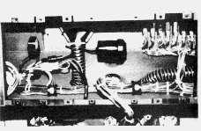
Remove Circuit Breakers
To remove all of the circuit breakers(1) as an assembly, proceed as follows:
1. Remove the two screws(2), and pull the mounting plate, with the circuit breakers attached, down into the panel housing.
2. Disconnect the wires and remove the assembly from the housing.
To remove individual circuit breakers, proceed as follows:
1. Remove the rubber cover and nut from the reset button.
2. Pull the assembly down into the panel housing.
3. Disconnect the wires and remove the circuit breaker from the housing.
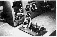
Remove Low Air Pressure Warning Buzzer
The warning buzzer(22) is located behind the panel. Remove from the housing by separating snap connector(23), and removing bolts(24).
Remove Flasher Unit
The flasher unit(18) is located behind the panel. Remove by carefully pulling it free of the socket.
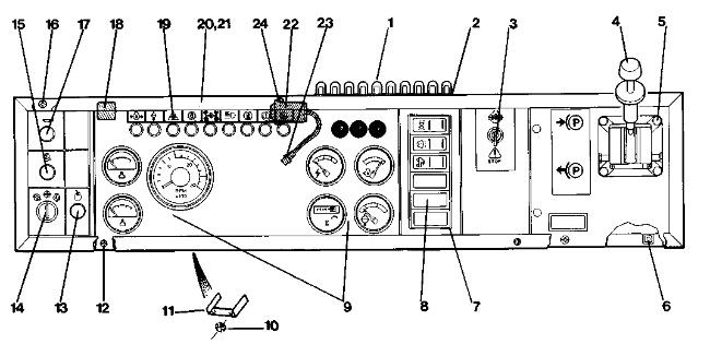
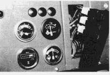
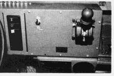
Dash Panel Arrangement (1) Circuit Breakers (2) Screws (3) Differential Lock Air Valve (4) Parking Brake Hand Control Valve (5) Bolts (6) Screws (7) Switch Mounting Plate (8) Switches (9) Gauges (10) Nuts (11) Brackets (12) Screws (13) Ether Inject Switch (14) Isolator Switch (15) Engine Stop Switch (16)
Right Hand Panel Components
Remove Panel
Remove screws(6) and lift out the panel to the extent of the parking brake hand control air hoses.
Parking Brake Hand Control Valve
Mark for identification on reassembly, and disconnect the air pipes. Remove bolts(5) and lift out the valve(4).
Remove
Differential
Lock Air Valve
Mark for identification on reassembly and disconnect the pipes from the air valve(3). Remove the nut from the front of the panel, and withdraw the valve from the back.
Remove Switches
Remove the switch mounting plate(7) by pushing out carefully from inside the panel housing, and disconnect the wires. Remove individual switches from the mounting plate, by pressing the switch out from the back of the plate.
Screws (17) Horn Valve (18) Flasher Unit (19) Warning Lights (20) Trim (21) Screws (22) Low Air Pressure Warning Buzzer (23) Snap Connector (24) Bolts
Previous Screen
Product: ARTICULATED TRUCK
Model: D35HP ARTICULATED TRUCK 3FD
Configuration: 3406 Engine Emissions Upgrade Group Retrofit Tier I Equivalent Level for D40D, D350D, D400D Articulated Truck 3FD00001-UP (MACHINE)
Disassembly and Assembly
ARTICULATED DUMP TRUCK OPERATOR'S STATION & ELECTRICAL SYSTE Media Number -SENR8188-00
Electrical System Switches and Sensors
Electrical System Switches and Sensors
Torque Convertor Lock Up Circuit - D35HP, D400, D44B and D550B
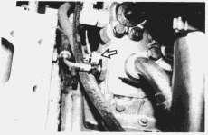
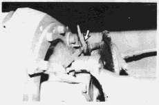
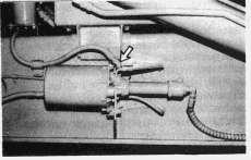
D35HP and D400 Lock Up Speed Switch
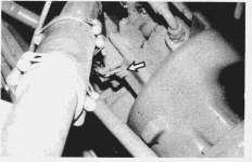
D35HP and D400 Lock Up Sensing Probe (Magnetic Pick Up)
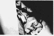
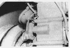
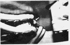
D35HP and D400 Lock Up Solenoid Valve
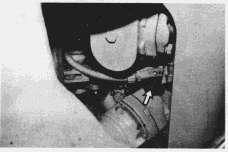
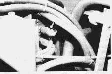
Torque Converter (Transmission Oil) Temperature Senders
Inter-Axle Differential Lock Indicator Switches
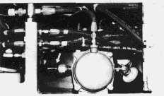
D44B and D550B Lock Up Speed Switch
D44B and D550B Lock Up Sensing Probe (magnetic Pick Up)
D44B and D550B Lock Up Solenoid Valve
D35HP, D400, D44B and D550B
D25C, D30C, D35C, D350C, D250B and D300B
All
Wheel Drive Indicator Switches
Brake Convertor Overstroke Indicator Switches
D25C, D30C, D35C, D350C, D250B and D300B
D35HP and D400
D44B
D550B
D250B and D300B Tractor
Suspension Level Inhibit Switches
D250B and D300B Trailer
D25C, D30C and D350C Trailer
D25C, D30C, D35C, D350C, D250B, D300B, D35HP, D400, D44B and D550B Service Brake Switch
D25C, D30C, D35C, D350C, D35HP Secondary Brake Relay Switch
D400 Parking Brake Switch
This is the sample of the manual if you need complete manual click on the Download button