

Note: Use Bookmarks panel to navigate
This is the sample of the manual click on the download link for complete manual
Note: Use Bookmarks panel to navigate
This is the sample of the manual click on the download link for complete manual
For some reason if link does not work download this pdf and then click

Product: INDUSTRIAL ENGINE
Model: D353C INDUSTRIAL ENGINE 46B
Configuration: D353 ENGINE 46B01558-UP
Disassembly and Assembly
D353 INDUSTRIAL & MARINE ENGINES
Media Number -SEBR0508-00
SMCS - 1207-15; 1207-16; 1207-11; 1207-12
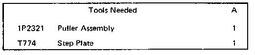
start by:
a) remove fuel injection pump housing
b) remove governor
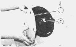
1. Remove cover (1), nut (2) and lock.
-11/10/2001
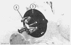
2. Remove accessory drive gear (3) with tooling (A).
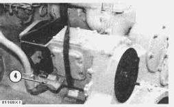
3. Remove service meter (4) and fasten a hoist to accessory drive housing.
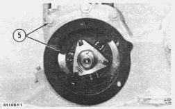
4. Remove bolts (5), locks and accessory drive housing.
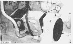
1. Put accessory drive housing (1) in place on engine. Install bolts and locks that hold drive housing to timing gear housing.
Install service meter.
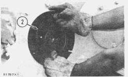
3. Heat accessory drive gear (2) to temperature of 300°F (149°C). Install gear, lock and nut on accessory drive shaft.
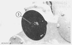
4. After gear is cold, tighten nut (3) to a torque of 325 ± 25 lb. ft. (440 ± 35 N·m).
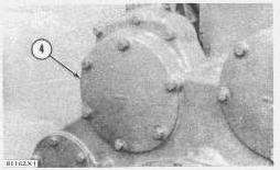
5. Install cover (4) and bolts on flywheel housing.
end by:
a) install fuel injection pump housing
b) install governor
c) check timing of camshaft for fuel injection pump. See TIMING CAMSHAFT FOR FUEL INJECTION PUMP in TESTING AND ADJUSTING SECTION
start by:
a) remove accessory drive housing
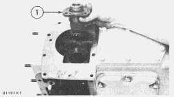
1. Remove pinion assembly (1) from drive housing.
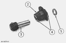
2. Push pinion shaft (3) out of washer (5) with a press. Remove bearings (4) from pinion cage (2).
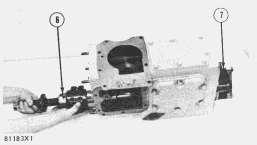
3. Remove drive shaft (6) and bearing cage (7) from drive housing.
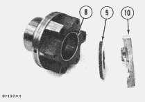
4. Remove thrust collar (10), washer (9) and bearings (8) from bearing cage.
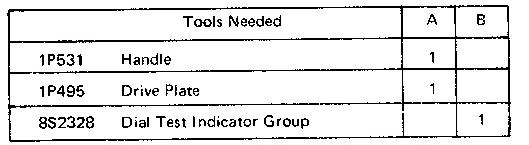
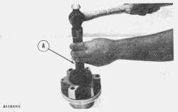
1. Install the bearings in bearing cage with tooling (A).
2. Install the washer and thrust collar on bearing cage. Install the cage assembly on drive housing.
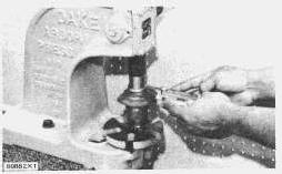
3. Install the bearings in pinion cage with a press. Install pinion shaft in cage and push washer on pinion shaft with a press. Pinion shaft end play must be .004 ± .002 in. (0.10 ± 0.05 mm). Put two thickness gauges between washer and bearing while pushing washer on shaft.
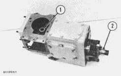
4. Install drive shaft (2) and pinion assembly (1) in the drive housing.
5. Install fuel injection pump housing on accessory drive housing. Install fuel transfer pump adapter housing on fuel injection pump housing.
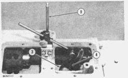
6. Make a measurement of pinion free movement (backlash) with tool group (B). Hold pinion gear (3) up and push bevel gear (4) toward adapter housing while making measurement. Free
movement (backlash) must be .002 to .006 in. (0.05 to 0.15 mm). Add or remove shims from behind bevel gear to make adjustment of free movement (backlash).
end by:
a) install accessory drive housing
Copyright 1993 - 2024 Caterpillar Inc. All Rights Reserved. Private Network For SIS Licensees.
Tue Nov 5 23:49:47 UTC+0530 2024
Product: INDUSTRIAL ENGINE
Model: D353C INDUSTRIAL ENGINE 46B
Configuration: D353 ENGINE 46B01558-UP
Disassembly and Assembly
D353 INDUSTRIAL & MARINE ENGINES
SMCS - 1063-11; 1063-12
Remove Aftercooler
1. Remove the coolant from the engine cooling system.
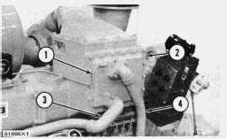
2. Disconnect vent line (1).
3. Remove water supply line (3) and return line (4).
4. Remove cover (2) from aftercooler housing.
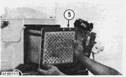
5. Remove aftercooler (5) from housing.
Install Aftercooler
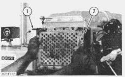
1. Install two guide bolts (1) 3/8"-16NC 5 in. long in the top corners of aftercooler housing.
2. Install aftercooler (2) in housing. Be sure dowel on back of aftercooler engages with holes in aftercooler housing.
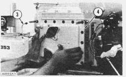
3. Install cover (4) on aftercooler housing.
4. Connect vent line (3) and install the water supply line and return line.
5. Fill engine with coolant to correct level.
Product: INDUSTRIAL ENGINE
Model: D353C INDUSTRIAL ENGINE 46B
Configuration: D353 ENGINE 46B01558-UP
Disassembly and Assembly
D353 INDUSTRIAL & MARINE ENGINES
SMCS - 1051-11; 1051-12
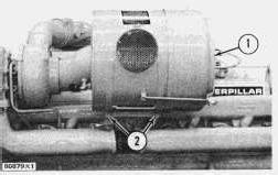
1. Remove bolts (2) from bands that hold air cleaner in place.
2. Pull air cleaner (1) free from turbocharger and remove it.
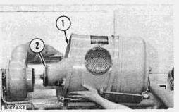
1. Put grease on O-ring (2) and install air cleaner in turbocharger.
2. Put bands (1) in place and install the bolts.
Product: INDUSTRIAL ENGINE
Model: D353C INDUSTRIAL ENGINE 46B
Configuration: D353 ENGINE 46B01558-UP
Disassembly and Assembly
D353 INDUSTRIAL & MARINE ENGINES
SMCS - 1405-11; 1405-12
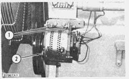
1. Disconnect the wiring from alternator.
2. Loosen bolts (1) and remove bolt (2) from alternator.
3. Remove the belt from the pulley.
4. Remove the bolts that hold alternator.
5. Remove alternator from engine.
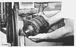
1. Put the alternator in position on the engine.
2. Install the bolts for the alternator.
3. Put belt in position on pulley and tighten the bolts holding the alternator.
NOTE: For correct belt tension, See V-Belt Tension Chart in SPECIFICATIONS.
4. Connect the wiring to the alternator.
Product: INDUSTRIAL ENGINE
Model: D353C INDUSTRIAL ENGINE 46B
Configuration: D353 ENGINE 46B01558-UP
Disassembly and Assembly
D353 INDUSTRIAL & MARINE ENGINES
Media Number -SEBR0508-00
SMCS - 1211-11; 1211-12

start by:
a) remove camshaft
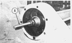
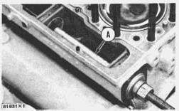
1. Remove the camshaft bearings with tool group (A) as shown.

-11/10/2001
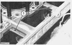
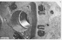
1. Install camshaft bearings with tool group (A) as shown. Oil holes in bearings must be in alignment with oil passages (1) from oil pockets in cylinder block. The rear camshaft bearing does not have a pocket and the location of oil passage is on the side of bore as shown.
end by:
a) install camshaft
Copyright 1993 - 2024 Caterpillar Inc. All Rights Reserved. Private Network For SIS Licensees.
Wed Nov 6 00:03:34 UTC+0530 2024
Product: INDUSTRIAL ENGINE
Model: D353C INDUSTRIAL ENGINE 46B
Configuration: D353 ENGINE 46B01558-UP
Disassembly and Assembly
D353 INDUSTRIAL & MARINE ENGINES
Media Number -SEBR0508-00
SMCS - 1210-11; 1210-12
start by:
a) remove cylinder head assembly
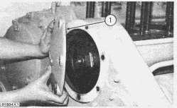
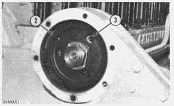
1. Remove cover (1) from flywheel housing.
Date -01/09/1980 Date Updated -11/10/2001
2. Turn crankshaft until holes in camshaft gear (2) are in alignment with bolts (3).
3. Remove bolts and locks from thrust washer.
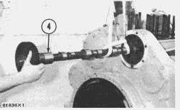
4. Pull camshaft (4) out far enough to fasten a hoist to it.
5. Remove camshaft from engine. Weight of camshaft is 70 lb. (32 kg).
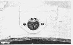
1. Turn crankshaft until timing pointer is in alignment with timing mark (TC No. 1 & 6) on flywheel.
2. Check position of camshaft (1) for fuel injection pump. If timing pin (3) can be installed No. 1 piston is at top center of compression stroke.
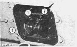
If notch (2) in camshaft (1) is 180° away from timing pin, crankshaft must be turned 360°.
NOTE: Above steps must be followed to put crankshaft in correct position for camshaft installation.
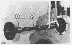
3. Put clean oil in camshaft bearings and on bearing surfaces (4) of camshaft.
4. Fasten a hoist to camshaft (5) and install camshaft in engine.
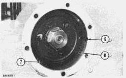
5. Before camshaft gear (8) engages with idler gear (7), turn camshaft until "V" mark on gear is in alignment with bolt hole in timing gear housing. After camshaft gear is engaged with idler gear check alignment of "V" mark with bolt hole by installing a bolt (6) between gear teeth of camshaft gear.
6. Install bolts and locks in thrust washer.
7. Install cover on flywheel housing.
end by:
a) install cylinder head assembly
1993 - 2024 Caterpillar Inc.
Network For SIS Licensees. Wed Nov 6 00:03:20 UTC+0530 2024

Product: INDUSTRIAL ENGINE
Model: D353C INDUSTRIAL ENGINE 46B
Configuration: D353 ENGINE 46B01558-UP
Disassembly and Assembly
D353 INDUSTRIAL & MARINE ENGINES
SMCS - 3302-15; 3302-16
start by:
a) remove the oil pump drive shaft
b) remove the clutch drive spider
1. Put the rear side of the clutch drive spider (4) in a vertical position.
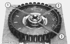
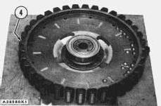
2. Remove four bolts (1) and two locks (2) from the rear side of the clutch drive spider (4).
3. Remove plate (3).
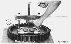
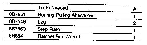
4. Put tooling (A) in position on the spider (4) to remove the bearing assembly (5).
5. Use tooling (A) to pull the bearing assembly (5) from the clutch drive spider (4).
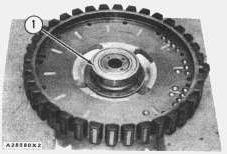
1. Heat bearing assembly (1) in oil to 200°F to 240°F (93°C to 115°C) maximum before installation.
2. Install bearing assembly (1) in an arrangement so the grease seal is away from the clutch drive spider (2).
3. Install plate (3).
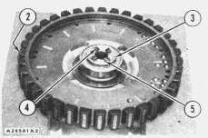
4. Install four bolts (4) and two locks (5) that hold bearing assembly (1) in rear side of the clutch drive spider (2).
end by:
a) install the clutch drive spider
b) install the oil pump drive shaft
Copyright 1993 - 2024 Caterpillar Inc. All Rights Reserved.
Private Network For SIS Licensees.
Wed Nov 6 00:00:47 UTC+0530 2024
Product: INDUSTRIAL ENGINE
Model: D353C INDUSTRIAL ENGINE 46B
Configuration: D353 ENGINE 46B01558-UP
Disassembly and Assembly
D353 INDUSTRIAL & MARINE ENGINES
SMCS - 3306-15; 3306-16
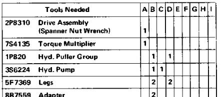
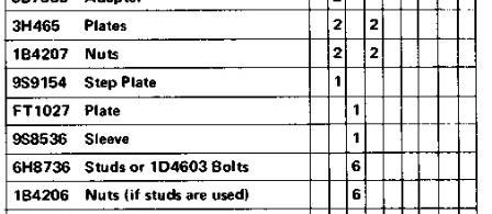
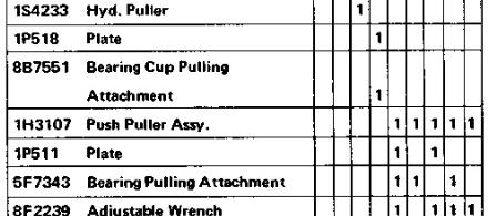
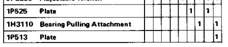
start by:
a) remove clutch shaft.
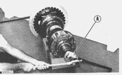
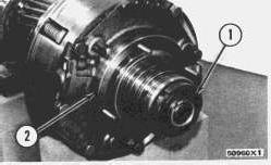
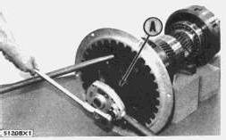
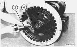
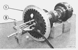
5. Pull spider (5) from the clutch shaft using tool (B).
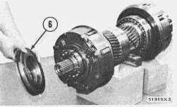
6. Remove bearing carrier (6).
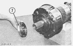
7. Remove bearing (7).
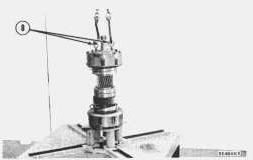
8. Install two 5/8"-11NC forged eyebolts (8) in forward clutch. Fasten hoist and put clutch shaft on transmission stand.
This is the sample of the manual click on the download link for complete manual
For some reason if link does not work download this pdf and then click